DUPLO CORPORATION System 4000 DYNAMIC ... - Godar Machinery
DUPLO CORPORATION System 4000 DYNAMIC ... - Godar Machinery
DUPLO CORPORATION System 4000 DYNAMIC ... - Godar Machinery

You also want an ePaper? Increase the reach of your titles
YUMPU automatically turns print PDFs into web optimized ePapers that Google loves.
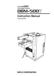
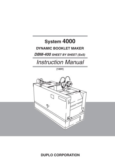
<strong>System</strong> <strong>4000</strong><br />
<strong>DYNAMIC</strong> BOOKLET MAKER<br />
DBM-400 SHEET BY SHEET (SxS)<br />
Instruction Manual<br />
[120V]<br />
<strong>DUPLO</strong> <strong>CORPORATION</strong>
The DBM-400 Sheet by Sheet (SxS) conforms with FCC regulations only when used in the<br />
following system configurations.<br />
<strong>System</strong>1:DB-10+DR-14+DBM-400 SxS+DBM-400T+DBM-400LS+DBM-400K<br />
<strong>System</strong>2:DB-10+DB-10TR+DBM-400 SxS+DBM-400T+DBM-400LS+DBM-400K<br />
• This equipment has been tested and found to comply with the limits for a Class B digital device, pursuant to Part 15 of<br />
the FCC Rules. These limits are designed to provide reasonable protection against harmful interference in a residential<br />
installation. This equipment generates, uses and can radiate radio frequency energy and, if not installed and used in<br />
accordance with the instructions, may cause harmful interference to radio communications. However, there is no<br />
guarantee that interference will not occur in a particular installation. If this equipment does cause harmful interference<br />
to radio or television reception, which can be determined by turning the equipment off and on, the user is encouraged<br />
to try to correct the interference by or more of the following measures:<br />
• Reorient or relocate the receiving antenna.<br />
• Increase the separation between the equipment and receiver.<br />
• Connect the equipment into an outlet on a circuit different from that to which the receiver is connected.<br />
• Consult the dealer or an experienced radio/TV technician for help.
INTRODUCTION<br />
Thank you for purchasing a DBM-400 sheet by sheet SxS. To ensure correct usage, please<br />
read this instruction manual thoroughly, especially the section “Safety Precautions”. After<br />
reading, please keep this instruction manual handy for future reference.<br />
CONTENTS<br />
1. Safety Precautions .............................2<br />
2. Usage Precautions .............................5<br />
2-1. Power Supply .................................................... 5<br />
2-2. Operating Environment ..................................... 5<br />
2-3. Storage Conditions ........................................... 5<br />
2-4. Maintenance ..................................................... 5<br />
3. Names and Functions of the Parts ...6<br />
3-1. External View .................................................... 6<br />
3-2. Internal Parts..................................................... 7<br />
3-3. Control Panel .................................................. 11<br />
4. Stitching Head ..................................14<br />
4-1. Names and Functions of Parts........................ 14<br />
4-2. Wire................................................................. 15<br />
4-3. Setting the Wire .............................................. 16<br />
4-4. How to Stitch Tests ......................................... 18<br />
4-5. Removing Wires.............................................. 19<br />
4-6. Adjusting Parts ................................................ 20<br />
5. Stitching Range ................................21<br />
6. Stitching Normal Size Paper ...........23<br />
6-1. Before Starting ................................................ 23<br />
6-2. Saddle-Stitching Double Letter and Letter Paper<br />
........................................................................ 29<br />
6-3. Side-Stitching Letter Paper (No Folding) ........ 30<br />
6-4. Fine Adjustment in Step Mode ........................ 30<br />
6-5. Other Functions .............................................. 32<br />
6-6. After Starting ................................................... 33<br />
6-7. After Completing Operations........................... 34<br />
7. Memorizing .......................................35<br />
8. Numerically Inputting the Paper Size ... 36<br />
8-1. Saddle-Stitching and Folding .......................... 36<br />
8-2. Side-Stitching .................................................. 42<br />
8-3. Corner-Stitching .............................................. 44<br />
8-4. No-Stitching No-Folding .................................. 47<br />
9. Binding ..............................................48<br />
9-1. Using the Auxiliary Roller Stay ........................ 48<br />
9-2. Using the Auxiliary Roller Unit ........................ 50<br />
9-3. Using the Paper Ejection Roller Unit............... 51<br />
9-4. Using the Paper Guide.................................... 52<br />
9-5. Using the Back Stopper and Roller ................. 53<br />
9-6. Using the Stitching Stopper and<br />
Folding Stopper............................................... 54<br />
9-7. Using the Folding Guide (For Folding) ............ 54<br />
9-8. Using the Guides After Folding ....................... 55<br />
9-9. Using the Press Roller .................................... 56<br />
9-10. Using the Belt Stacker Unit ............................. 57<br />
10. Using Function Keys........................59<br />
11. Precautions Using Emergency Stop<br />
Switch ................................................62<br />
12. LCD Error Messages and<br />
Corresponding Actions to Take ......63<br />
12-1. Error Messages..............................................63<br />
12-2. Paper Jam Display.........................................64<br />
12-3. Serious Problems...........................................65<br />
12-4. Other Messages.............................................66<br />
13. The Unit will Stop in These Cases ..67<br />
14. Cleaning ............................................68<br />
15. Maintenance of the Stitching Head.69<br />
16. Specifications ...................................70<br />
1
1. Safety Precautions<br />
Always observe the following cautions and warnings to prevent personal injury and damage to<br />
properties.<br />
2<br />
The degree of dangers and damages that could occur is indicated in two levels by the<br />
following symbols.<br />
WARNING: Ignoring this symbol could result in serious injury or even death.<br />
CAUTION: Ignoring this symbol could result in injury or physical damage.<br />
The following symbols indicate the various types of actions to be performed or<br />
avoided.<br />
This symbol indicates a forbidden action.<br />
means “Do not disassemble.”<br />
means “Do not touch.”<br />
This symbol indicates actions that must be performed.<br />
means “Disconnect the power plug.”<br />
WARNINGS:<br />
Do not place metal objects or vessels containing liquids on top of the unit. The entry of any<br />
metal object or liquid could result in fire or electrical shock.<br />
Do not insert any metal or combustible object inside this unit. This could result in fire or<br />
electrical shock.<br />
Do not touch or insert foreign objects into any rotating part during operation. This could<br />
result in injury.<br />
Do not remove the cover or back panel. This unit contains high-voltage components that<br />
could cause electrical shock.<br />
Do not disassemble, modify or repair this unit. This could result in fire or electrical shock,<br />
or injury. Contact your dealer when repairs are necessary.<br />
Use only the power supply voltage specified on the main label. Use of other voltages could<br />
result in fire or electrical shock.<br />
Keep this unit and the power cord away from heaters and heater vents. Excessive heat<br />
could melt the cover or power cord covering and result in fire or electrical shock.
CAUTIONS:<br />
Do not use flammable sprays inside or near the unit (e.g. when cleaning the unit).<br />
Flammable gas may ignite and cause fire or combustion.<br />
1. Safety Precautions<br />
Make sure that the current consumption indicated on the main label does not exceed the<br />
capacity rating of the power outlet. Also do not connect other equipment to the same power<br />
outlet, otherwise the power outlet mat overheat and cause fire.<br />
Remove any dust that has accumulated on the power plug prongs and the surface from<br />
which the prongs extend. Accumulated dust can cause fire.<br />
If any foreign objects such as metal or liquid enters the unit, turn off the power switch<br />
immediately and disconnect the power plug from the power outlet.<br />
Failure to do so could result in fire or electrical shock. Contact your dealer immediately.<br />
Do not damage the power cord or power plug. (Do not scratch, alter, bend, twist, pull or<br />
place heavy objects on the power cord or power plug.)<br />
This could result in damage, fire or electrical shock.<br />
Always grip the plug when disconnecting the power plug from the power outlet. Pulling on<br />
the power cord could cause damage, resulting in fire or electrical shock.<br />
Do not handle the power plug with wet hands. This could result in electrical shock.<br />
Before cleaning this unit, turn off the power switch and disconnect the power plug from the<br />
power outlet. Accidental operation of the unit during cleaning could result in injury.<br />
Always disconnect the power plug from the power outlet when this unit is not to be used for<br />
an extended period. Failure to do so could result in fire due to leakage current if the<br />
insulation should deteriorate.<br />
Install this unit on a level, stable stand or floor, with sufficient space around it. Failure to do<br />
so could result in the unit overturning and injury.<br />
Do not install this unit in a location where there is excessive humidity or where it may be<br />
exposed to water. Failure to do so could result in deterioration of the insulation, fire or<br />
electrical shock.<br />
Disconnect the power plug from the power outlet before attempting to move this unit.<br />
Failure to do so could result in power cord damage, fire or electrical shock.<br />
3
1. Safety Precautions<br />
4<br />
Do not use inflammable<br />
gas or solvent<br />
inside unit.<br />
It could cause fire<br />
or combustion.<br />
Warning/Caution label location<br />
Do not use inflammable<br />
gas or solvent<br />
inside unit.<br />
It could cause fire<br />
or combustion.
2. Usage Precautions<br />
2-1. Power Supply<br />
Make sure the power supply used is always within the following range.<br />
120V AC 50Hz<br />
Plug the power cord plug directly into a wall power outlet.<br />
This equipment shall be installed near the socket-outlet where the plug on the power supply<br />
cord is easily accessible.<br />
2-2. Operating Environment<br />
Operate this unit in the following environment.<br />
• Temperature range: 5 to 35 °C (41 to 95°F)<br />
• Humidity range: 20 to 85% RH (no condensation)<br />
• Avoid exposure to direct sunlight.<br />
• Avoid dusty locations<br />
• Avoid locations with vibration<br />
• Avoid locations that are salty<br />
• Avoid locations with special chemicals<br />
Store this unit in the following environment.<br />
2-3. Storage Conditions<br />
• Temperature range: -5 to +50 °C (23 to 122°F)<br />
• Humidity range: 10 to 90% RH (no condensation)<br />
• Avoid exposure to direct sunlight.<br />
• Avoid dusty locations<br />
• Avoid locations with vibration<br />
• Avoid locations that are salty<br />
• Avoid locations with special chemicals<br />
2-4. Maintenance<br />
To maintain the performance of this unit, you should never apply oil or grease to parts<br />
(unless specified in this instruction manual to do so).<br />
Please contact your dealer if a problem is suspected.<br />
5
3. Names and Functions of the Parts<br />
6<br />
4<br />
3-1. External View<br />
No. Name Function<br />
1 POWER Switch<br />
When the switch is turned on, power is supplied and the unit sets into the standby state.<br />
2 Control Panel Unit<br />
Displays instructions and messages on operating the unit.<br />
3 Emergency stop switch Press this switch only to stop the unit immediately.<br />
Press the Stop Key on the collator to stop the unit normally.<br />
Turn the switch clockwise to release.<br />
4 Clearance Adjusting Knob Used to adjust the clearance with the first press roller.<br />
5 Top Cover<br />
Cover to ensure safety. Be sure to close the cover before starting operations.<br />
Note) Do not fan paper nor perform other jobs on top of this cover during operations when<br />
connected to other devices, because operations may stop due to vibration.<br />
6 Wire<br />
Paper is stitched with this wire.<br />
7 Fixing Bolt<br />
Used to secure the unit and adjust the height of the unit to the peripheral units.<br />
8 Power Cord<br />
Connect to a wall outlet.<br />
9 Connecting Cable<br />
Signal transmission cable to be connected to the upstream processing device.<br />
bk Shutter<br />
Door for inserting the manual handle. Normally use closed.<br />
If open, the safety switch operates and the unit will not operate.<br />
bl Manual Handle<br />
Used to clean the press roller. Rotates only in the clockwise direction.<br />
bm Sub Cover<br />
Cover for use by service personnel. Normally fixed by screws and cannot be opened.<br />
bn Stacker Plate<br />
Receives single-folded paper.<br />
bo Paper Guide Roller Unit Guides discharged paper into the stacker section and conveys the paper to the stacker plate on<br />
the conveyance belt.<br />
Belt Stacker Unit<br />
Transmits single-folded paper to the stacker plate using the conveyance belt.<br />
Guide<br />
Guides unfolded paper to the stacker unit.<br />
Stacker Unit<br />
Receives unfolded paper.<br />
bp<br />
bq<br />
br<br />
L side<br />
bm<br />
bk<br />
bl<br />
1<br />
7<br />
5<br />
2<br />
5<br />
6<br />
8<br />
3<br />
R side<br />
9<br />
bn<br />
bq<br />
bo<br />
Paper direction<br />
br<br />
bp
1 Entrance Section<br />
3-2. Internal Parts<br />
3. Names and Functions of the Parts<br />
No. Name Function<br />
bs Movable Side Guide<br />
Guides side of the paper when stitching.<br />
bt Back Jog<br />
Aligns the tail end of the paper.<br />
ck Stitcher Position Warning Displays the relation between the position of the stitcher and folding knife during stitching and<br />
Label<br />
folding operations.<br />
Pointer<br />
Displays the stitching position.<br />
Paper Discharge Roller Unit Discharges stitched paper.<br />
Conveyance Roller Unit Conveys paper to the stitching stopper via the conveyance belt.<br />
Head Holder<br />
Holds the stitching head.<br />
Side Jog Guide<br />
Aligns side of the paper.<br />
Auxiliary Roller Stay<br />
Conveys conveyance force to the paper.<br />
cl<br />
cm<br />
cn<br />
co<br />
cp<br />
cq<br />
bs<br />
bt<br />
ck cl cn cm<br />
co<br />
cq<br />
cp<br />
7
3. Names and Functions of the Parts<br />
2 Stitching Section<br />
8<br />
No. Name Function<br />
cr<br />
cs<br />
ct<br />
dk<br />
dl<br />
dm<br />
dn<br />
do<br />
dp<br />
dq<br />
dr<br />
ds<br />
dt<br />
ek<br />
el<br />
em<br />
en<br />
dt<br />
cr<br />
cs<br />
Pressure Release Lever<br />
Ejection Roller Unit<br />
Paper Guide<br />
Side-Stitching Stopper<br />
Stitching Head R<br />
Lever<br />
Stitching Head L<br />
Paper Guide<br />
Side Guide<br />
Saddle-Stitching Stopper<br />
Paper Guide<br />
Conveyance Roller Unit<br />
Upper Guide Unit<br />
Back Stopper<br />
Guide<br />
Roller Moving Knob<br />
Auxiliary Side Guide<br />
dp<br />
ct<br />
ct<br />
dk<br />
dl<br />
do<br />
dr<br />
dm<br />
dn<br />
dq<br />
ek<br />
Releases the pressure of the conveyance roller at the R side.<br />
Discharges stitched paper. Attach and detach the roller at the L side according to the paper<br />
width.<br />
Prevents the saddle-stitched paper from curling.<br />
Rises to stop the paper during side-stitching.<br />
Unit which stitches paper.<br />
Lift up the lever and move to the L side when not performing stitching operations.<br />
Unit which stitches paper.<br />
Prevents the paper from projecting out of the stopper when side-stitching paper.<br />
Determines the stopping position before folding paper.<br />
Rises to stop the paper during saddle-stitching.<br />
Prevents large sized paper from curling.<br />
Conveys conveyance force to the paper. Jammed paper can be removed more easily when<br />
detached.<br />
Prevents incoming paper from flipping.<br />
Aligns the rear edge position before folding paper.<br />
Used to prevent the tip of the paper from being raised when discharging after stitching.<br />
Moves the roller.<br />
Determines the stopping position before folding large paper.<br />
ds<br />
en<br />
el<br />
em
3 Folding Section<br />
ep<br />
3. Names and Functions of the Parts<br />
No. Name Function<br />
Guide<br />
Use when the cover is deformed as shown in “9-8. Using the Guide after Folding”.<br />
Pressure Release Lever Releases the pressure of press rollers 2.<br />
Lever<br />
Changes and releases the pressure of press rollers 3.<br />
Press Rollers 2<br />
Presses the fold line of the paper.<br />
Press Rollers 3<br />
Further presses the fold line of the paper.<br />
Clearance Adjusting Lever Adjusts the clearance between press rollers 2.<br />
Press Rollers 1<br />
Catches the paper lifted up by the folding blade.<br />
eo<br />
ep<br />
eq<br />
er<br />
es<br />
et<br />
fk<br />
et<br />
eq<br />
es<br />
er<br />
eo<br />
es<br />
er<br />
eq<br />
et<br />
fk<br />
9
3. Names and Functions of the Parts<br />
4 Folding Stopper Section<br />
No. Name Function<br />
fl Paper Guide<br />
Prevents the folded paper from curling.<br />
fm<br />
Folding Stopper<br />
Normally, remains lifted to stop the paper.<br />
The stopper goes down if not be folded.<br />
10<br />
fm<br />
fl
Control Panel<br />
2 1<br />
Lamps/Displays<br />
1<br />
2<br />
3<br />
4<br />
5<br />
6<br />
7<br />
8<br />
9<br />
bu<br />
bl<br />
bm<br />
bn<br />
bo<br />
bp<br />
bq<br />
br<br />
bs<br />
2<br />
Power Lamp<br />
PAPER JAM Lamp<br />
LCD<br />
1<br />
3-3. Control Panel<br />
F<br />
1 2 3 C<br />
4 5 6 0<br />
7 8 9<br />
Saddle-Stitching Lamp<br />
Side-Stitching Lamp<br />
No-Stitching Lamp<br />
Folding Lamp<br />
No-Folding Lamp<br />
Step Mode Stitching Area Lamp<br />
Step Mode Folding Area Lamp<br />
Back Jog Lamp<br />
Side Guide Lamp<br />
Stitching Head R Lamp<br />
Stitching Head L Lamp<br />
Back Stopper Lamp<br />
Stitching Position Lamp<br />
Folding Position Lamp<br />
Input Memory Lamp<br />
Operation Keys<br />
1<br />
2<br />
3<br />
4<br />
5<br />
6<br />
7<br />
8<br />
9<br />
bk<br />
bl<br />
bm<br />
bn<br />
bo<br />
bp<br />
bq<br />
br<br />
bs<br />
bt<br />
ck<br />
3. Names and Functions of the Parts<br />
6 bs<br />
br bm<br />
5<br />
3 3 4 5 8 bt bq bn bl bn 9 6 4<br />
7<br />
9<br />
bq bs br<br />
bo bp<br />
bp<br />
Select Memory Key<br />
Execute Memory Key<br />
Escape Key<br />
Function Key<br />
Shift Key<br />
Change Key<br />
Numerical Keys<br />
Clear Key<br />
Set Key<br />
Select Stitch Key<br />
Select Fold Key<br />
Step Mode Key<br />
Select Unit Key<br />
Move (±=) Key<br />
Move (+≠) Key<br />
Select Parallel Movement Key<br />
Parallel Movement (=) Key<br />
Parallel Movement (+) Key<br />
Input Memory Key<br />
Jog Key<br />
bo<br />
ck bm<br />
7 8 bu<br />
bk<br />
bl<br />
11
3. Names and Functions of the Parts<br />
Names and Functions of Control Panel<br />
12<br />
Operation Keys Display<br />
Function<br />
1Select Memory Key<br />
2Execute Memory Key<br />
3Escape Key<br />
4Function Key<br />
5Shift Key<br />
6Change Key<br />
7Numerical Keys<br />
8Clear Key<br />
9Set Key<br />
bkSelect Stitch Key<br />
blSelect Fold Key<br />
1Power Lamp<br />
2PAPER JAM Lamp<br />
(3LCD)<br />
(3LCD)<br />
(3LCD)<br />
(3LCD)<br />
(3LCD)<br />
4Saddle-Stitching Lamp<br />
5Side-Stitching Lamp<br />
6No-Stitching Lamp<br />
7Folding Lamp<br />
8No-Folding Lamp<br />
Lights up when the power switch is turned on.<br />
Lights up when paper feeding jam occurs.<br />
Used to select the memory number (paper size).<br />
Used to set each unit to the size selected by the 1 Select Memory Key.<br />
Used to stop operations while executing function (programs)<br />
using the 4 Function Key and 6 Change Key or to exit the error<br />
state when errors such as JAM, etc. occur.<br />
Used to set various functions.<br />
Used to change the functions of each key.<br />
Used to change contents selected by the 1 Select Memory Key.<br />
Used to input numbers such as the paper size, etc.<br />
Used to clear numbers input by the 7 Numerical Keys.<br />
Used to set numbers input by the 7 Numerical Keys.<br />
Used to select the stitching mode.<br />
Lights up when saddle-stitching has been selected.<br />
Lights up when side-stitching has been selected.<br />
Lights up when no-stitching has been selected.<br />
Used to select the folding mode.<br />
Lights up when folding has been selected.<br />
Lights up when folding has not been selected.
Operation Keys Display<br />
Function<br />
bmStep Mode Key<br />
bo<br />
bp<br />
Move Keys<br />
bq<br />
Select Parallel<br />
Movement Key<br />
brbs<br />
Parallel Movement Keys<br />
btInput Memory Key<br />
ckJog Key<br />
bn<br />
Select<br />
Unit Key<br />
9Step Mode Stitching<br />
Area Lamp<br />
blBack Jog Lamp<br />
bmSide Guide Lamp<br />
bnStitching Head R Lamp<br />
boStitching Head L Lamp<br />
buStep Mode Folding Area<br />
Lamp<br />
bpBack Stopper Lamp<br />
bqStitching position<br />
Lamp<br />
brFolding position Lamp<br />
bsInput Memory Lamp<br />
3. Names and Functions of the Parts<br />
Used to finely adjust the size by actually conveying paper.<br />
When blinking, indicates that no paper is conveyed into the<br />
stitching area.<br />
When lit, indicates that the paper is inside the stitching area, and<br />
guides in the area can be finely adjusted.<br />
Used to select the position of bl back jog, bm side guide, bn<br />
stitching head R, bo stitching head L.<br />
Enables the back jog to be finely adjusted using the bo Move<br />
(±=) and bp Move (+≠) Keys.<br />
Enables the side guide to be finely adjusted using the bo Move<br />
(±=) and bp Move (+≠) Keys.<br />
Enables the stitching head R to be finely adjusted using the bo<br />
Move (±=) and bp Move (+≠) Keys.<br />
Enables the stitching head L to be finely adjusted using the bo<br />
Move (±=) and bp Move (+≠) Keys.<br />
Enables the back stopper to be finely adjusted when the paper is<br />
inside the folding area.<br />
Enables the back stopper to be finely adjusted using the bo Move<br />
(±=) and bp Move (+≠) Keys.<br />
Used to finely adjust the stitching and folding positions.<br />
Enables the stitch stopper and back jog to be moved<br />
simultaneously in the direction of the br Parallel Movement (=)<br />
Key or bs Parallel Movement (+) Key, and to be finely adjusted.<br />
Enables the folding stopper and back stopper to be moved<br />
simultaneously in the direction of the br Parallel Movement (=)<br />
Key or bs Parallel Movement (+) Key, and to be finely adjusted.<br />
While the bs Input Memory Lamp is lit, enables the data changed<br />
using the bo and bp Move Keys and br and bs Parallel Movement<br />
Keys to be memorized.<br />
While the 9 Step Mode Stitching Area Lamp is lit, each time it is<br />
pressed, the jog will move. When pressed while off, the<br />
conveyance belt and conveyance roller will move.<br />
13
4. Stitching Head<br />
14<br />
4-1. Names and Functions of Parts<br />
bp<br />
3<br />
2<br />
5<br />
bq<br />
bo<br />
bq<br />
7<br />
8<br />
9<br />
bk<br />
bm<br />
bn<br />
1<br />
1<br />
4<br />
6<br />
bl
No. Name Function<br />
1<br />
2<br />
3<br />
4<br />
5<br />
6<br />
7<br />
8<br />
9<br />
bk<br />
bl<br />
bm<br />
bn<br />
bo<br />
bp<br />
bq<br />
Wire Guide Pin<br />
Wire Return Stopper Unit<br />
Felt<br />
Wire Return Stopper<br />
Fixing Knob<br />
Upper Wire Tube<br />
Wire Length Adjusting Knob<br />
Triangular Knob<br />
Feed Wheel<br />
Lower Wire Tube<br />
Cap Screw<br />
Bolt<br />
Wire Straightener<br />
Leaf Spring<br />
Former<br />
Adjusting Handle<br />
• American wires:No. 25 to 28<br />
• Europian wires:No. 26 to 30<br />
Guides the wire.<br />
Prevents the wire supplied from being pulled back.<br />
Cleans the wire surface and lubricates slightly.<br />
Used to remove the wire.<br />
Fixed the wire guide to the 6 upper wire tube.<br />
Path of wire.<br />
Used to adjust the wire length.<br />
Used to switch whether to stitch or not.<br />
Rotating it with the adjusting handle feeds the wire. Used to feed the wire to<br />
the bk lower wire tube.<br />
Path of wire.<br />
Secure the stitching head to the head holder using the cap screw (0.16 inch<br />
across).<br />
Adjusts the left and right bending and length of the wire when the adjusting<br />
handle is inserted into the head of this bolt.<br />
Straightens the wire.<br />
Holds the bp former.<br />
Holds the wire horizontally and forms a C shape.<br />
Used to adjust the balance of leg length. (Provided with the unit.)<br />
4-2. Wire<br />
4. Stitching Head<br />
The wire diameter corresponding to these numbers will differ according to the region.<br />
Wire diameters from 0.020 inch to 0.014 inch can be used, but use of the 0.020 inch wire is recommended for stable stitching.<br />
15
4. Stitching Head<br />
1. Pass the wire between the 1 wire<br />
guide pins.<br />
2. Pass the wire through the two 3 felts<br />
and through the 2 wire return stopper<br />
unit.<br />
3. Set the 8 Triangular knob at the no<br />
stitching position, insert the wire into<br />
the tip of the 6 Upper wire tube. Make<br />
sure the wire is not deformed.<br />
16<br />
4-3. Setting the Wire<br />
Stitching<br />
Wire<br />
2 wire return<br />
stopper unit<br />
8 Triangular knob<br />
Wire guide pin<br />
Wire<br />
3 Felts<br />
6 Upper wire tube<br />
No stitching
4. Insert the wire from the 2 Upper wire<br />
tube, and feed it gently inside using<br />
the pliers provided until the tip of the<br />
wire reaches the bk Lower wire tube.<br />
Make sure the wire is not deformed.<br />
5. Set the 8 Triangular knob at the<br />
stitching position.<br />
6. Press the bq Adjusting handle against<br />
the head of the 9 Feed wheel and rotate<br />
it clockwise, and feed the wire<br />
out. Rotate the adjusting handle twice.<br />
Note<br />
If the wire is bent, it will not go into the bk lower wire<br />
tube and will jam. Pull out the wire, cut off the bent<br />
part, and set again.<br />
9Feed wheel<br />
bk Lower wire tube<br />
9 Feed wheel<br />
Stitching<br />
Wire<br />
bkLower wire tube<br />
8 Triangular knob<br />
4. Stitching Head<br />
6 Upper wire tube<br />
No stitching<br />
bq Adjusting handle<br />
17
4. Stitching Head<br />
4-4. How to Stitch Tests<br />
1 Turn on the power.<br />
2 Select memory 2, set each unit to Letter<br />
Saddle Stitching and Folding. For<br />
details of operations, refer to “6-2.<br />
Saddle-stitching Double Letter and<br />
Letter Paper” and “9. Binding”.<br />
18<br />
Note<br />
Remove the auxiliary roller stay before carrying out<br />
the operations.<br />
3 Press the bm Step Mode Key twice. The<br />
driving system such as the conveyance<br />
belt will start operating.<br />
4 Slide few sheets of Letter paper manually.<br />
5 The paper will stop at the Letter<br />
saddle-stitching position.<br />
6 Press the bm Step mode Key once to<br />
jog paper.<br />
7 While pressing the 5 Shift Key, press<br />
the bm Step Mode Key. The paper will<br />
move 0.4 inch, and is stitched once.<br />
This operation can be carried out six<br />
times. (Without using the 5 Shift<br />
Key).<br />
8 After completing the operation, remove<br />
the paper.<br />
9 The stitch test mode ends when the 8<br />
Clear Key is pressed.<br />
Note<br />
• If the wire is bent, it will not go into the bp former<br />
but may jam instead. In this case, adjust the bn wire<br />
straightener. (Refer to 4-6. 3. Straightening the<br />
wire.)<br />
• Carry out stitching several times and check the<br />
stitches and wire sent.<br />
• If problems are seen, check if the wire is set<br />
properly.<br />
F<br />
2 3 C<br />
5 6 0<br />
8 9<br />
5<br />
8<br />
bm
1. Rotate the 8 triangular knob to the<br />
“no stitching” position.<br />
2. Pull out the wire upwards while pressing<br />
down the 4 wire adjusting stopper.<br />
3. Return the 8 triangular knob to the<br />
stitching position.<br />
4-5. Removing Wires<br />
Stitching<br />
8 Triangular knob<br />
4. Stitching Head<br />
No stitching<br />
4Wire adjusting<br />
stopper<br />
19
4. Stitching Head<br />
1. Adjusting the wire length<br />
3. Straightening the wire<br />
20<br />
Adjust the length of the wire after cutting it according<br />
to the thickness of the stitched paper.<br />
• Rotating the 7 wire length adjusting knob<br />
clockwise increases the wire length.<br />
• Rotating counterclockwise decreases the wire<br />
length.<br />
• The length of the wire changes by 0.064 inch with<br />
each rotation.<br />
2. Adjusting the wire leg length<br />
• After setting the wire length, adjust so that the<br />
bent legs of the wire are equal.<br />
• Put the bq Adjusting handle on the bm Bolt to<br />
rotate.<br />
• Rotating clockwise makes right leg longer.<br />
• Rotating counterclockwise makes left leg<br />
longer.<br />
counterclockwise<br />
clockwise<br />
• Straighten the wire for better stitching.<br />
The straightener is factory set. Adjustments are<br />
required when using wires other than those<br />
specified.<br />
4-6. Adjusting Parts<br />
When adjusted in<br />
direction A:<br />
When adjusted in<br />
direction B:<br />
The wire will become this shape.<br />
A<br />
7Wire length adjusting knob<br />
Bolt<br />
B<br />
bqAdjusting handle<br />
Wire (Straight shape)<br />
Wire straightener
5. Stitching Range<br />
Stitching Position<br />
Saddle-Stitching<br />
• Stitches at the measurement shown<br />
by the pointer.<br />
• The number of stitches can be selected<br />
between one and two.<br />
• Refer to 16. Specifications for the<br />
length and width.<br />
The standard stitching position is as below:<br />
When the width (W) is between 8.27 inch<br />
and 14 inch: 1:2:1<br />
For example, when the width (W) is 9.45 inch, stitch at<br />
the positions of 2.36 inch and 7.09 inch from the paper<br />
edge.<br />
• The paper cannot be stitched within<br />
0.6 inch from the edge of the paper.<br />
• The distance between two stitches<br />
must be over 2.95 inch.<br />
8.27–14<br />
Paper<br />
Stitch position label<br />
L<br />
Pointer<br />
2.36<br />
60<br />
180<br />
7.09<br />
W 240<br />
9.45<br />
W<br />
(Unit: inch)<br />
0.6 or<br />
more<br />
1.48 or<br />
more<br />
0.6 or<br />
more<br />
(Unit: inch)<br />
21
5. Stitching Range<br />
Side Stitching<br />
• Stitches 0.24 inch from the edge of the<br />
paper.<br />
• The stitches along the width are the<br />
same as saddle-stitching.<br />
When selecting saddle-stitching and folding, do not stitch at<br />
the 7 marked position. (8 positions)<br />
When stitching at positions other than the center along the<br />
length of the paper, refer to 8. Numerically Inputting the<br />
Paper Size.<br />
22<br />
Note<br />
0.6 or<br />
more<br />
2.95 or<br />
more<br />
0.6 or<br />
more<br />
0.24<br />
L<br />
Stitch Position Label<br />
(Unit: inch)
6. Stitching Normal Size Paper<br />
Do not align paper nor perform other operations<br />
on the top cover during operations<br />
connected to other devices as operations<br />
may stop due to vibrations.<br />
Turn on the power switch of the unit.<br />
Read before use<br />
6-1. Before Starting<br />
Power switch ON<br />
• The DBM-400 Sheet by Sheet (SxS) is a sheet-by-sheet version of the DBM-400. Note that because the<br />
specifications of the DBM-400 SxS differ from those of the DBM-400, it is recommended that you read<br />
16. Specifications (P.70) before use. Also note that the DBM-400 SxS is not fully automatic, and that<br />
when changing paper sizes or the number of sheets per set it is accordingly necessary to manually move<br />
the wheels above the belt stacker, to move the auxiliary side guides underneath the folder, to adjust the<br />
spacing of the folder roller, to remove and attach the auxiliary roller stays, to adjust the paper guides, and<br />
to adjust the paper guides above the folder stopper.<br />
Always be sure to remember the following points when executing individual procedures.<br />
6-1-1 Points to remember when changing the paper size or number of sheets per set<br />
Be sure to remember the following points when changing the paper size:<br />
It is impossible to input paper sizes on the DBM-400 SxS when attached to the DB-10C. (The size, however, will be<br />
displayed.) The paper size must be input on the DB-10C. For this reason, Select memory key 1 and Execute memory<br />
key 2 are disabled on the DBM-400 SxS.<br />
When the power to the DB-10C is turned off, however, it is possible to input paper sizes or to change the paper size<br />
using the DBM-400 SxS control panel.<br />
The procedures described in this manual for entering or changing paper sizes are the procedures intended for use when<br />
the DBM-400 SxS is not connected to the DB-10C.<br />
The Escape key, Step key, and other keys remain enabled when the DBM-400 SxS is connected to the DB-10C.<br />
* After changing the paper size, always be sure to check the points described on the following page before beginning<br />
paper feeding.<br />
23
6.Stitching Normal Size Paper<br />
1. Removing and attaching the auxiliary roller stays<br />
• There are three locations on the DBM-400 SxS where auxiliary roller stays may be attached. (For further information,<br />
see 9-1: Using the auxiliary roller stays.)<br />
When you wish to change the paper size, the paper size cannot be changed unless the auxiliary roller stays are removed.<br />
(Note that this must be done in order to prevent interference between the auxiliary roller stays and the moving unit.)<br />
When changing the paper size, always be sure to remove the auxiliary roller stays. When the paper size has been<br />
changed, follow the instructions given in 9-1: Auxiliary roller stays, to place the stays back into their proper position.<br />
24<br />
* Changing the paper size with the auxiliary roller stays attached does not display this error message on the DBM-400<br />
SxS. Instead, it will be displayed on the DB-10C. To clear the error condition, press the DBM-400 SxS Escape key 3<br />
and then change the paper size again.<br />
2. Adjusting the auxiliary side guides underneath the folder<br />
• When changing the paper size, check the position of the auxiliary side guides en to make sure that the width is greater<br />
than the paper width. If the width between the side guides is less than the paper width, the paper will come into contact<br />
with the guides and it will become impossible to feed the paper.<br />
(For further information, see 9-7: Using the folding guides.)<br />
3. Changing the position of the wheel units on the belt stacker<br />
• When changing the paper size, make sure that the paper guide roller unit bo on the belt stacker is located in a proper<br />
position with respect to the paper length.<br />
If it is not located in the proper position, paper will not be ejected, and cause a paper jam. Error 08 will then be<br />
displayed.<br />
(For further information, see 9-10: Using the belt stacker unit.)<br />
4. Adjusting the spacing of the folder rollers<br />
• When changing the number of sheets per set, paper jams may occur in the roller unit if the spacing between the rollers<br />
in the folder unit is not correct.<br />
When changing the number of sheets per set, always make sure that both of the spaces between the first folding rollers<br />
and second folding rollers are correct, respectively.<br />
(For further information, see 9-9: Using the press rollers.)
6.Stitching Normal Size Paper<br />
5. Adjusting the ct paper guides and the dr paper guides<br />
• When the number of sheets per set is changed, there may be times when paper fails to be fed to the stopper or, when<br />
paper runs over the stopper if the height of the paper guides is not adjusted correctly.<br />
Make sure that the paper guides have been adjusted to the correct height. (For further information, see 9-4: Using the<br />
paper guides.)<br />
6-1-2 Points to remember when using step mode<br />
When adjusting in step mode, be sure to load the full number of sheets per set.<br />
6-1-3 Action to be taken when paper is not aligned well<br />
If paper is not aligned well, perform the following steps to correct the problem.<br />
1 Turning subset off<br />
The number of sheets to be stored in the buffer for each set is usually entered on the DB-10C, and the number of jog<br />
repetitions per set is determined from the time allocated to that number of sheets.<br />
When paper is not aligned well in the saddle-stitching folding stopper section, release the subset setting using the dip<br />
switch of the DB-10C.<br />
After the mode has been changed, the input values of the first three (or more) sheets in the set will be stored in the<br />
buffer, and all the other sheets will be fed through the DB-10C and then stacked in the DBM-400 SxS.<br />
2 Changing the position of the Back Jog auxiliary rollers<br />
The position of the rollers located above the rubber feed rollers in the back jogger unit may be changed back and forth<br />
as shown in the diagrams below to change the angle at which paper is fed. Note that the position should be changed<br />
according to how paper is fed from between rollers.<br />
Note that the paper guides may be removed or attached by unscrewing the screw A as required when using extra-thin<br />
paper.<br />
Loosen the screw B in few turns, and adjust the position of the auxiliary rollers.<br />
Paper direction<br />
Shaft<br />
Screw B<br />
Screw A<br />
Shaft<br />
Shaft<br />
25
6.Stitching Normal Size Paper<br />
3 Checking paper guides<br />
26<br />
• When performing saddle stitching and folding, the angle and the height of the paper guide dr should be adjusted<br />
if sheets fail to reach the stitching stopper. (If the paper guide presses down the paper too heavily, it will become<br />
difficult for paper to reach the stopper and the alignment of paper will be poorer.)<br />
• When performing saddle stitching and folding, if sheets bounce back from the stitching stopper, make sure that<br />
the upper guide dt touches lightly and paper is fed properly. (If paper bounces back , the alignment will become<br />
worse.)<br />
• Loosen the knob screw to adjust the height of the upper guide dt.<br />
Paper guide<br />
Knob screw<br />
Knob screw to adjust the angle<br />
Knob screw to adjust the height<br />
Upper guide
6-1-4 Points to remember when paper runs over the saddle stitching stopper<br />
• Function mode may be used to change the timing at which the stitching stopper rises. Changing this timing makes it<br />
possible to relieve problems which would otherwise occur when the stitching stopper fails to rise properly. (For further<br />
information, see Item 2 of 10 : Using Function Keys. (P.59))<br />
When the power is turned on, a buzzer sounds, and the following is displayed on the LCD.<br />
Note<br />
Next, the memory number just before the power is turned off is displayed as shown below. If an error message is displayed, check<br />
the details of the error.<br />
*1. 17.00x11.00 (Example : When the memory number is 1)<br />
The meaning of the display is as follows.<br />
*1. 17.00x11.00<br />
a...Memory number<br />
Flow of paper.<br />
This unit is provided with eight different paper processing memory patterns. Memories 1 to 3 are input with the normal paper<br />
sizes while memories 4 to 8 are for the users to memorise. Memories 4 to 8 are input with paper size 17 inch 11 inch beforehand.<br />
Note<br />
£<br />
£<br />
£<br />
a L W<br />
Unit<br />
(inch)<br />
*1. 17.00 x 11.00<br />
*2. 11.00 x 08.50<br />
*3. 08.50 x 11.00<br />
*4. 17.00 x 11.00<br />
*5. 17.00 x 11.00<br />
*6. 17.00 x 11.00<br />
*7. 17.00 x 11.00<br />
*8. 17.00 x 11.00<br />
Memories 1 to 8 can be changed. (overwritten)<br />
L<br />
6.Stitching Normal Size Paper<br />
W<br />
27
6. Stitching Normal Size Paper<br />
Selecting the memory number<br />
1) • Each time the 1 Select Memory Key is pressed, the<br />
display on the LCD scrolls as follows.<br />
2) • When the 1 Select Memory Key is pressed while<br />
pressing the 5 Shift Key, the display scrolls in the<br />
reverse.<br />
28<br />
• As the display scrolls, the LED on the control panel<br />
displays the processing type (stitching/folding).<br />
• 7 Numerical Keys 1 to 8 correspond to memory<br />
numbers 1 to 8. They can be used directly to select<br />
the desired memory after pressing the 1 Select<br />
Memory Key.<br />
• While selecting the memory number, the LCD will<br />
blink.<br />
• To cancel selection, press the 3 Escape Key.<br />
The display on the LCD<br />
£ £ £ £ £ £ £ £<br />
∗ 1. 17.00 x 11.00<br />
∗ 2. 11.00 x 08.50<br />
∗ 3. 08.50 x 11.00<br />
∗ 4. ##.## x ##.##<br />
∗ 5. ##.## x ##.##<br />
∗ 6. ##.## x ##.##<br />
∗ 7. ##.## x ##.##<br />
∗ 8. ##.## x ##.##<br />
(Unit: inch)<br />
LCD<br />
1
6. Stitching Normal Size Paper<br />
6-2. Saddle-Stitching Double Letter and Letter Paper<br />
Saddle-stitching Double Letter Paper<br />
1) • Set the LCD to [*1. 17.00 x 11.00] according to the<br />
previous chapter "Selecting the Memory Number".<br />
(The LCD blinks.)<br />
2) • When the 2 Execute Memory Key is pressed, the<br />
guides move.<br />
3) • When they stop moving, the LCD stops blinking and lights up, and a buzzer sounds.<br />
4) • To perform fine adjustments, refer to “6-4. Fine Adjustment in Step Mode”.<br />
Note<br />
The standard stitching position is at the 11 inch width of the paper [1:2:1].<br />
Stitching Letter Paper<br />
1) • Set the LCD to [*2. 11.00 x 08.50] according to the previous chapter "Selecting the Memory Number".<br />
(The LCD blinks.)<br />
2) • When the 2 Execute Memory Key is pressed, the guides move.<br />
3) • When they stop moving, the LCD stops blinking and lights up, and a buzzer sounds.<br />
4) • To perform fine adjustments, refer to “6-4. Fine Adjustment in Step Mode”.<br />
Note<br />
The standard stitching position is at the 8.5 inch width of the paper [1:2:1].<br />
*1. 17.00 x 11.00<br />
2<br />
29
6. Stitching Normal Size Paper<br />
30<br />
6-3. Side-Stitching Letter Paper (No Folding)<br />
1) • Set the LCD to [*3. 08.50 x 11.00] according to the previous chapter "Selecting the Memory Number".<br />
(The LCD blinks.)<br />
2) • When the 2 Execute Memory Key is pressed, the guides move.<br />
3) • When they stop moving, the LCD stops blinking and lights up, and a buzzer sounds.<br />
4) • To perform fine adjustments, refer to “6-4. Fine Adjustment in Step Mode”.<br />
Note<br />
The standard stitching position is at the 11 inch width of the paper [1:2:1].<br />
6-4. Fine Adjustment in Step Mode<br />
• When using step mode, always be sure to set the<br />
number of copies to '1' on the printer.<br />
1) • Press the bm Step Mode Key while the unit is<br />
stopping.<br />
(The 9 Step Mode Stitching Area Lamp blinks in<br />
green.)<br />
2) • Input one set in the upstream unit, and press the<br />
start button of the upstream unit. For details, refer to<br />
the Instruction Manual of the upstream unit.<br />
• This unit will start operating when the upstream<br />
unit starts.<br />
When one set of paper ejected from the upstream<br />
unit is conveyed to the stitching stopper, the 9<br />
Step Mode Stitching Area Lamp will light up, and<br />
at the same time, the side jogger and back jogger<br />
will start jogging. Wait for jogging to complete.<br />
After jogging completes, the back jogger, side<br />
guide,stitching heads R and L can be moved<br />
separately.<br />
Note<br />
Do not input the number of set more than 2 sets.<br />
3) • Select the unit to be fine adjusted using the bn<br />
Select Unit Key.<br />
Note<br />
The LED of the unit selected lights up.<br />
9<br />
bm<br />
bn
4) • The unit selected at 3) will move by 0.004 inch each<br />
time the bo Move (± =) Key or the bp Move (+ ≠)<br />
Key is pressed. It will move by 0.04 inch each time<br />
the bo Move (± =) Key or the bp Move (+ ≠) Key<br />
is pressed while pressing the 5 Shift Key.<br />
Note<br />
When setting the guides, move them out completely,<br />
and then move them inwards again.<br />
Precautions on fine adjustments<br />
Move the side guide carefully when the back jogger is<br />
raised. The side guide may be damaged if it touches the<br />
back jogger.<br />
5) • Press the ck Jog Key to align the paper, and check<br />
if the stitching area has been adjusted finely.<br />
• To carry out fine adjustments again, perform steps<br />
3) to 5).<br />
6) • After completing fine adjustments in the stitch area,<br />
press the bm Step Mode Key again.<br />
• After stitching, the paper will be conveyed to the<br />
folding stopper.<br />
• When conveyed to the folding stopper, the 9 Step<br />
Mode Stitching Area Lamp will go off and the bu<br />
Step Mode Folding Area Lamp and the bp Back<br />
Stopper Lamp will light up together, and the back<br />
stopper will start operating.<br />
• The back stopper can be moved in this state.<br />
7) • The back stopper unit will move by 0.004 inch each<br />
time the bo Move ( ± = ) Key or bp Move<br />
( + ≠ ) Key are pressed.<br />
Note<br />
When setting the back stopper, move it backward<br />
completely, and move it forward again.<br />
6. Stitching Normal Size Paper<br />
bp bo<br />
9<br />
bk<br />
bp<br />
ck<br />
bm<br />
bp bo<br />
31
6. Stitching Normal Size Paper<br />
8) • After completing fine adjustments of the folding<br />
area, press the bm Step Mode Key.<br />
32<br />
• The paper will be ejected folded, and the bu Step<br />
Mode Folding Area Lamp and the bp Back Stopper<br />
Lamp will go off, and the bs Input Memory Lamp<br />
will light up.<br />
9) • To store the fine adjustment data, press the bt Input<br />
Memory Key.<br />
• If the data need not be stored, press the 8 Clear<br />
Key. The bs Input Memory Lamp will go off.<br />
Note<br />
The bt Input Memory Key is effective only while the<br />
bs Input Memory Lamp is lit. Once it is pressed, data<br />
will be stored in the memory displayed on the LCD<br />
(overwritten) and the bs Input Memory Lamp will go<br />
off.<br />
To check paper alignment at the folding<br />
area in the step mode<br />
1) Press the bm Step Mode Key once. ( 9 blinks.)<br />
2) Press the bm Step Mode Key another time. (The<br />
conveyance system operates.)<br />
3) Press the bm Step Mode Key while pressing the 5 Shift Key.<br />
The back stopper operates to align the paper.<br />
4) Return to step 7) in 6-4.<br />
To check paper alignment at the stitching<br />
area in the step mode<br />
1) Press the bm Step Mode Key once. ( 9 blinks.)<br />
2) Press the bm Step Mode Key another time. (The<br />
conveyance system operates.)<br />
3) Press the bm Step Mode Key another time. The back<br />
stopper and side joggers operate to align the paper.<br />
4) Return to step 3) in 6-4.<br />
Note<br />
To stop the step mode halfway through, press the 8 Clear<br />
Key.<br />
6-5. Other Functions<br />
F<br />
2 3 C<br />
5 6 0<br />
8 9<br />
8<br />
5 8<br />
0<br />
C<br />
bs<br />
bm<br />
bt<br />
9<br />
bm
6-6. After Starting<br />
To finely adjust stitching and folding positions<br />
1) • Press the bq Select Parallel Movement Key, and select the stitch position or folding position.<br />
6. Stitching Normal Size Paper<br />
• Each time the bq Select Parallel Movement Key is pressed, the lamps light up in the following order.<br />
Only the bq Stitching Position Lamp lights up = Only the br Folding Position Lamp lights up = both lamps light up<br />
= both lamps go off.<br />
Meaning of LED lamps<br />
• While the bq Stitching Position Lamp is lit, it<br />
indicates that the back jog and the Saddle stitching<br />
stopper unit can be adjusted.<br />
• While the br Folding Position Lamp is lit, it<br />
indicates that the back stopper and the folding<br />
stopper unit can be adjusted.<br />
• While both lamps are lit, it indicates that the back<br />
jogger, saddle stitching stopper, back stopper,<br />
folding stopper units can be adjusted.<br />
• When both lamps are off, it indicates that no units<br />
are being selected.<br />
2) • Each time the br ( = ) or bs ( + ) Parallel Movement Key is pressed, the unit selected at step 1) will move in the direction<br />
of the key by 0.004 inch.<br />
• Pressing this key lights up the bs Input Memory Lamp.<br />
bs<br />
bs br<br />
Stitching and folding line lines<br />
8<br />
bt<br />
C<br />
bq<br />
br<br />
bq<br />
33
6. Stitching Normal Size Paper<br />
3) • To store the fine adjustment data, press the bt Input Memory Key.<br />
• Turn off the power of the unit.<br />
• Remove the auxiliary roller stay from the inside.<br />
34<br />
• If the data need not be stored, press the 8 Clear Key. The bs Input Memory Lamp will go off.<br />
Note<br />
Parallel movement can be performed using the bm Step Mode Key.<br />
The bt Input Memory Key is effective only while the bs Input Memory Lamp is lit. Once it is pressed, data will<br />
be stored in the memory number displayed on the LCD (overwritten) and the bs Input Memory Lamp will go off.<br />
Precautions on memorizing<br />
Take note that the slight difference between the memory data and actual positions of each unit cannot be corrected by<br />
performing fine adjustment in the Step Mode only once. Pay particular attention when adjusting the stitching position and<br />
folding position by parallel movement.<br />
If the actual position differs<br />
1. Change the size using the same memory number.<br />
2. Perform fine adjustment in the step mode another time.<br />
Match the memory data and actual position by repeating steps 1 and 2 above (repeat until no more fine adjustment is<br />
required.).<br />
Follow this precautions especially when using a paper size used often.<br />
Note<br />
6-7. After Completing Operations<br />
Before turning off the power, always memorize the paper size desired.<br />
If it is not memorized, the previous size (data) will be effective.<br />
If the data need not be memorized, press the 8 Clear Key while the unit is stopping to turn off the bs Input Memory<br />
Lamp.
7. Memorizing<br />
• The bs Memory Input Lamp lights up immediately<br />
after “6-4. Fine Adjustment in Step Mode” ends or<br />
immediately after performing fine adjustments by the<br />
parallel movement.<br />
• Immediately after performing fine adjustment, to<br />
memorize the data, press the bt Input Memory Key.<br />
• When the Key is pressed, the data after the fine<br />
adjustment will be stored in the memory number<br />
displayed on the LCD (overwritten) and the bs Input<br />
Memory Lamp will go off.<br />
Note<br />
• The bt Input Memory Key is effective only<br />
while the bs Input Memory Lamp is lit.<br />
• If the data need not be stored, press the 8 Clear<br />
Key while the unit is stopping. The bs Input<br />
Memory Lamp will go off.<br />
• If parallel movements are performed during<br />
operations, the bs Input Memory Lamp will light<br />
up after operations stop.<br />
bs<br />
bt<br />
35
8. Numerically Inputting the Paper Size<br />
36<br />
8-1. Saddle-Stitching and Folding<br />
1) • As the paper size is input in numerals, measure the<br />
paper size on the scale.<br />
For example;<br />
L=13.6 inch W=9.2 inch<br />
2) • Select the number of the desired size to overwrite<br />
according to the previous section “Selecting the<br />
Memory Number”.<br />
For example;<br />
When 5 is selected, the LCD displays [*5. ##.## x<br />
##.##]. (The LCD blinks.)<br />
3) • When the 6 Change Key is pressed, the LCD<br />
displays [*5. L=##.##]. (The LCD will light up.)<br />
• Select the desired processing method.<br />
4) • Press the bk Select Stitch Key and select saddlestitching.<br />
L<br />
Paper feeding<br />
direction<br />
*5. ##.## x ##.##<br />
W<br />
bk<br />
1<br />
6
5) • Press bl Select Fold Key and select folding.<br />
6) • Input the length of the paper (L) as shown below.<br />
• Using the 7 Numerical Keys, input four digits.<br />
Example)<br />
Press the 7 Numerical Keys in the following order.<br />
However, input a value (L) between 11 and 18.5<br />
inch.<br />
Note<br />
1 3 6 0<br />
To clear the input number, press the 8 Clear Key.<br />
To return to the most recent input mode, press the 3<br />
Escape Key.<br />
7) • When the 9 Set Key is pressed, the LCD displays<br />
[*5.W=##.##].<br />
[W] is the width of the paper.<br />
8. Numerically Inputting the Paper Size<br />
bl<br />
Paper feeding direction<br />
F<br />
L<br />
1 2 3 C<br />
4 5 6 0<br />
7 8 9<br />
F<br />
1 2 3 C<br />
4 5 6 0<br />
7 8 9<br />
9<br />
37
8. Numerically Inputting the Paper Size<br />
8) • Input the width of the paper (W) as shown below.<br />
38<br />
• Using the 7 Numerical Keys, input four digits.<br />
Example)<br />
Press the 7 Numerical Keys in the following order.<br />
0 9 2 0<br />
However, input a value (W) between 8.27 and 14inch.<br />
Note<br />
To clear the input number to 0, press the 8 Clear Key.<br />
To return to the most recent input mode, press the 3<br />
Escape Key.<br />
9) • When the 9 Set Key is pressed, the LCD displays<br />
[*5.S=06.80].<br />
[S] is the length from the saddle stitching stopper to<br />
the stitching position.<br />
*5. S=06.80<br />
Paper feeding direction<br />
F<br />
1 2 3 C<br />
4 5 6 0<br />
7 8 9<br />
F<br />
1 2 3 C<br />
4 5 6 0<br />
7 8 9<br />
9<br />
W
10) • Input the length [S] from the saddle stitching<br />
stopper to the stitching position.<br />
• The length is automatically calculated (from 1:1) [L<br />
x 1/2], and the LCD displays [*5. S=06.80].<br />
• To change the input, input the four digits again<br />
using the 7 Numerical Keys.<br />
The range is S=5.51 inch to the smaller value of L–<br />
5.51 inch or 8.86inch.<br />
11) • Press the 9 Set Key once. The LCD displays<br />
[*5. A=02.30].<br />
8. Numerically Inputting the Paper Size<br />
*5. A=02.30<br />
Stitching position<br />
Paper feeding direction<br />
S<br />
F<br />
1 2 3 C<br />
4 5 6 0<br />
7 8 9<br />
F<br />
1 2 3 C<br />
4 5 6 0<br />
7 8 9<br />
9<br />
39
8. Numerically Inputting the Paper Size<br />
12) • Next input the stitching position [A] at the R side.<br />
40<br />
• The position is automatically calculated (from<br />
1:2:1) [W x 1/4], and the LCD displays [*5.<br />
A=02.30].<br />
• To change the input, input the four digits again<br />
using the 7 Numerical Keys.<br />
However, the input range A is 15 to (W/2 – 1.58)<br />
inch.<br />
13) • Press the 9 Set Key once. The LCD displays<br />
[*5. B=06.90].<br />
14) • Next, input the stitching position [B] at the L side.<br />
• First calculate this position as follows (from 1:2:1);<br />
[W x 3/4]<br />
The LCD displays [*5. B=06.90].<br />
*5. B=06.90<br />
A<br />
Paper feeding direction<br />
F<br />
1 2 3 C<br />
4 5 6 0<br />
7 8 9<br />
B<br />
Stitch<br />
F<br />
1 2 3 C<br />
4 5 6 0<br />
7 8 9<br />
Paper feeding direction<br />
9<br />
Side R<br />
Side R<br />
Side L
• To change the input, input the four digits again<br />
using the 7 Numerical Keys.<br />
However, the input range B = (W/2+1.58) to (W–<br />
0.6) inch and within 13.19 inch.<br />
15) When connected to Duplo trimmer DBM-400T<br />
Note<br />
If connected to any downstream unit other than DBM-<br />
400T or if not connected to DBM-400T, proceed to<br />
16).<br />
• When the 9 Set Key is pressed once, the LCD<br />
displays [*5. F=06.67]. “F=6.67” is the final size.<br />
• If no changes are required, proceed to 16).<br />
• To change the value, input a 4-digit number in the<br />
same way using the 7 Numerical Keys and<br />
proceed to 16).<br />
(For details, refer to the instruction manual for DBM-<br />
400T.)<br />
16) • When the 9 Set Key is pressed, the LCD displays<br />
[*5. ? 13.60 x 09.20].<br />
17) • Perform the final check here.<br />
• If OK, press the 9 Set Key and memorize the<br />
value. The display will start blinking.<br />
• If NG, press the 3 Escape Key to return to the first<br />
display (the state when the 1 Select Memory Key<br />
was pressed), and the LCD displays [*1. ##.## x<br />
##.##] blinking.<br />
Input again.<br />
This ends input of paper size.<br />
8. Numerically Inputting the Paper Size<br />
*5. F=06.67<br />
*5. ? 13.60X09.20<br />
*1. ##.##X ##.##<br />
F<br />
1 2 3 C<br />
4 5 6 0<br />
7 8 9<br />
F<br />
F<br />
1 2 3 C<br />
4 5 6 0<br />
7 8 9<br />
1 2 3 C<br />
4 5 6 0<br />
7 8 9<br />
3<br />
F<br />
9<br />
1 2 3 C<br />
4 5 6 0<br />
7 8 9<br />
9<br />
9<br />
41
8. Numerically Inputting the Paper Size<br />
18) • Press the 2 Execute Memory Key and start moving<br />
the guides.<br />
42<br />
• When they complete moving, the LCD displays<br />
[*5. 13.60x09.20] and a buzzer sounds.<br />
• To perform fine adjustment, refer to “6-4. Fine<br />
Adjustment in Step Mode”.<br />
1) • Since paper size is input using numerals, measure the paper size on the scale.<br />
For example, L=8.27 inch, W=11.69 inch.<br />
*5. 13.60 x 09.20<br />
2) • Referring to the previous section "Selecting the Memory Number", select the number of the desired size to overwrite.<br />
For example, when 6 is selected, and the LCD display switches to [*6. ##.##x##.##].<br />
(The LCD blinks.)<br />
3) • When the 6 Change Key is pressed, the LCD displays [*6. L=##.##].<br />
• Select the desired processing method.<br />
4) • Press the bk Select Stitch Key and select side-stitching.<br />
5) • Press the bl Select Fold Key and select no-folding.<br />
6) • Input the length of the paper (L) as shown below.<br />
• Using the 7 Numerical Keys, input four digits.<br />
Example)<br />
Press the 7 Numerical Keys in the following order.<br />
0 8 2 7<br />
However, input a value (L) between 7.88 and 9.48 inch.<br />
Note<br />
To clear the input number to 0, press the 8 Clear Key.<br />
7) • When the 9 Set Key is pressed, the LCD displays<br />
[*6. W=##.##].<br />
[W] is the width of the paper.<br />
8-2. Side-Stitching<br />
2<br />
Paper feeding direction<br />
L=8.27 L=210<br />
W=11.69 W=297<br />
(Unit: inch)
8) • Using the 7 Numerical Keys, input four digits.<br />
Example)<br />
Press the 7 Numerical Keys in the following order.<br />
However, input a value between 8.27 and 14 inch.<br />
Note<br />
To clear the input number to 0, press the 8 Clear Key.<br />
9) • When the 9 Set Key is pressed, the LCD displays<br />
[*6. A=02.92].<br />
[A] is the stitching position length at the R side.<br />
• First calculate this position as follows (from 1:2:1);<br />
[W x 1/4]<br />
• To change the input, input the four digits again<br />
using the 7 Numerical Keys.<br />
However, input a value (A) between 0.6 and (W/2–<br />
1.58) inch.<br />
10) • When the 9 Set Key is pressed, the LCD displays<br />
[*6. B=08.76].<br />
[B] is the stitching position length at the L side.<br />
• First calculate this position as follows (from 1:2:1);<br />
[W x 3/4]<br />
• To change the input, input the four digits again<br />
using the 7 Numerical Keys.<br />
However, input a value (B) between (W/2+1.58)<br />
and (W–0.6) inch.<br />
11) • When the 9 Set Key is pressed, the LCD displays<br />
[*6. ? 08.27 x 11.69].<br />
12) • Perform the final check here.<br />
• If OK, press the 9 Set Key, and it will be memorized.<br />
8. Numerically Inputting the Paper Size<br />
• If NG, press the 3 Escape Key to return to the first display (the state when the 1 Select Memory Key was pressed),<br />
and the LCD display [*1. ##.##x##.##] blinks.<br />
This ends input of paper size.<br />
1 1 6 9<br />
13) • Press the 2 Execute Memory Key and start moving the guides.<br />
• When they complete moving, the LCD displays [*6. 08.27 x 11.67], and a buzzer sounds.<br />
• To perform fine adjustment, refer to "6-4. Fine Adjustment in the Step Mode".<br />
B<br />
A<br />
Paper feeding direction<br />
43
8. Numerically Inputting the Paper Size<br />
1) • Since paper size is input using numerals, measure the paper size on the scale.<br />
For example, L=8.27 inch, W=11.69 inch.<br />
2) • Select the number of the desired size to overwrite according to the previous section “Selecting the Memory Number”.<br />
For example, when 7 is selected, and the LCD displays [*7. ##.##x##.##].<br />
(The LCD blinks.)<br />
3) • When the 6 Change Key is pressed, the LCD displays [*7. L=##.##].<br />
• Select the desired processing method.<br />
4) • Press the bk Stitch Key and select side-stitching.<br />
5) • Press the bl Fold Key and select no-folding.<br />
6) • Input the length of the paper [L] as shown below.<br />
• Using the 7 Numerical Keys, input four digits.<br />
44<br />
Example)<br />
Press the 7 Numerical Keys in the following order.<br />
However, input a value (L) between 7.88 and 9.49 inch.<br />
Note<br />
To clear the input number to 0, press the 8 Clear Key.<br />
7) • When the 9 Set Key is pressed, the LCD displays [*7. W=##.##].<br />
[W] is the width of the paper.<br />
8) • Using the 7 Numerical Keys, input four digits.<br />
Example)<br />
Press the 7 Numerical Keys in the following order.<br />
However, input a value (W) between 8.27 and 14 inch.<br />
Note<br />
0 8 2 7<br />
1 1 6 9<br />
To clear the input number to 0, press the 8 Clear Key.<br />
8-3. Corner-Stitching
When Corner-Stitching at Right Side<br />
9) • When the 9 Set Key is pressed, the LCD displays<br />
[*7. A=02.92].<br />
[A] is the stitching position at the R side.<br />
However, input a value (A) between 0.6 and (W/2–<br />
1.58) inch.<br />
• First calculate this position as follows (from 1:2:1);<br />
[W x 1/4]<br />
10) • Input the four digits(0150)using the 7 Numerical<br />
Keys.<br />
However, input a value (A) between 0.6 and 4.27<br />
inch.<br />
11) • When the 9 Set Key is pressed, the LCD displays<br />
[*7. B=08.76].<br />
12) • When the 9 Set Key is pressed, the LCD displays [*7. ? 08.27 x 11.69].<br />
13) • Perform the final check here.<br />
• If OK, press the 9 Set Key to memorize this value. At this time, the display will start blinking.<br />
• If NG, press the 3 Escape Key to return to the first display (the state when the 1 Select Memory Key was pressed).<br />
The LCD display [*1. ##.##x##.##] blinks.<br />
Input again.<br />
This ends input of paper size.<br />
14) • Remove the clamp of the stitching head L side<br />
driver.<br />
15) • Rotate the 8 Triangular Knob of the stitching<br />
head to the “no stitching” position.<br />
Note<br />
When corner-stitching paper of the maximum width 14<br />
inch at the L side, be sure to move the stitching head<br />
with the clamp on the driver. If the clamp is not on the<br />
driver, the stitching head cannot be moved to the<br />
corner-stitching position.<br />
When performing the corner-stitching at the R side,<br />
avoid setting the stitching head R outside the area<br />
between 0.98 and 1.18inch.<br />
Proceed onto step 18).<br />
25-30<br />
15<br />
0.98-1.18<br />
8. Numerically Inputting the Paper Size<br />
0.60<br />
Paper feeding direction<br />
Paper feeding direction<br />
(Unit: inch)<br />
Clamp<br />
(Unit: inch)<br />
45
8. Numerically Inputting the Paper Size<br />
When Corner-Stitching at Left Side<br />
Steps 1 to 8 are the same. (page 44)<br />
Releasing guides<br />
Always be sure to release the guide unit when<br />
performing corner stitching on the left side.<br />
9) • Press the 9 Set Key once. The LCD displays<br />
[*7. A=02.92].<br />
10) • Press the 9 Set Key once. The LCD displays<br />
[*7. B=08.76].<br />
[B] is the L side stitching position measurement.<br />
However, input a value (B) between (W/2+1.58)<br />
and (W–06) inch.<br />
• First calculate this position as follows (from 1:2:1);<br />
[W x 3/4].<br />
11) • Input the four digits (2820) using the 7 Numerical<br />
Keys.<br />
However, input a value (A) between 7.43 and 11.09<br />
inch.<br />
12) • When the 9 Set Key is pressed, the LCD displays<br />
[*7. ? 08.27 x 11.69]<br />
13) • Perform the final check here.<br />
• If OK, press the 9 Set Key to memorize this value.<br />
At this time, the display will start blinking.<br />
• If NG, press the 3 Escape Key to return to the first<br />
display (the state when the 1 Select Memory Key<br />
was pressed). The LCD displays [*1. ##.## x ##.##]<br />
blinking.<br />
46<br />
This ends input of paper size.<br />
16) • Remove the clamp of the stitching head R side<br />
driver.<br />
17) • Rotate the 8 Triangular Knob of the stitching head<br />
to the non-stitching position.<br />
18) • When the 2 Execute Memory Key is pressed, the<br />
guides start moving.<br />
• When they complete moving, the LCD displays [*7.<br />
08.27 x 11.69], and a buzzer sounds.<br />
• To perform fine adjustment, refer to “6-4. Fine<br />
Adjustment in Step Mode”.<br />
15<br />
0.6<br />
Paper feeding direction<br />
(Unit: inch)
8-4. No-Stitching No-Folding<br />
Use this mode to convey paper to the Duplo stacker through the DBM-400 SxS.<br />
1) • Measure the width of the paper and input the value.<br />
For example, W=8.2 inch.<br />
2) • Select the number of the desired size to overwrite<br />
according to the previous section “Selecting the<br />
Memory Number”.<br />
For example, when 4 is selected, the LCD displays<br />
[*4. ##.## x ##.##].<br />
3) • Press the 6 Change Key. The LCD displays<br />
[*4. L=##.##].<br />
4) • Press the bk Select Stitch Key and set to the nostitching<br />
mode.<br />
5) • Press the bl Select Fold Key and set to the nofolding<br />
mode.<br />
6) • Value L need not be input.<br />
7) • Press the 9 Set key. The LCD displays<br />
[*4.W=##.##].<br />
W is the width of the paper.<br />
8) • Using the 7 Numerical Keys, input the four digits.<br />
Example)<br />
Press the 7 Numerical Keys in the following<br />
order.<br />
0 8 2 0<br />
9) • Press the 9 Set Key three times. The LCD displays<br />
[*4. ? 08.20].<br />
Note<br />
Values A and B (stitching positions) need not be<br />
input.<br />
10) • *Perform the final check here.<br />
*If OK, press the 9 Set Key to memorize this<br />
value. At this time, the display will start blinking.<br />
*If NG, press the 3 Escape Key to return to the<br />
first display (the state when the 1 Select Memory<br />
Key was pressed). The LCD displays [*1. ##.## x<br />
##.##] blinking.<br />
Input again.<br />
This ends input of paper size.<br />
11) • When the 2 Execute Memory Key is pressed, the<br />
guides start moving.<br />
• When they complete moving, the LCD displays [*4.<br />
08.20], and a buzzer sounds.<br />
12) • Attach the auxiliary roller stay.<br />
Refer to "9-1 Using the Auxiliary Roller Stay".<br />
Attach at parts A, B, C, and D.<br />
Note<br />
8. Numerically Inputting the Paper Size<br />
• Paper will jam if the paper guides are set too tightly<br />
against the paper thickness. Refer to "9-4 Using the<br />
Paper Guides", and distance the paper guides of the<br />
saddle-stitching and folding stoppers away from the<br />
paper.<br />
• Jams which occur near the stitching area may be<br />
caused by the incorrect timing of the paper<br />
discharge roller unit. In this case, change the setting<br />
of the function. Refer to “2” in “10. Using Function<br />
Keys”.<br />
47
9. Binding<br />
48<br />
9-1. Using the Auxiliary Roller Stay<br />
• The auxiliary roller stay for applying<br />
conveyance force to the paper can be<br />
attached to this unit at three locations.<br />
• To prevent guides from contacting<br />
each other, this unit is provided with<br />
sensors at A, B and C .<br />
If the auxiliary roller stay is attached<br />
to any one of these sensors, size cannot<br />
be changed.<br />
1 Attaching<br />
Fit the auxiliary roller stay to the<br />
square hole on the bracket at the R<br />
side.<br />
Auxiliary roller stay A<br />
Folding section<br />
Stitching head<br />
C B A<br />
Auxiliary roller stay<br />
Section A<br />
Auxiliary roller stay<br />
Section B<br />
Auxiliary roller stay<br />
Section C<br />
Bracket<br />
Auxiliary roller stay A<br />
Bracket<br />
Auxiliary roller stay B<br />
Auxiliary roller stay B
2 Attaching Conditions<br />
A<br />
m<br />
?<br />
Attaching Conditions for Positions A and B<br />
Attaching Conditions for Position C<br />
Saddle-Stitching<br />
Folding<br />
? means “attach”. m means “do not attach”.<br />
Stitching and Folding Conditions and Paper Length<br />
Saddle-Stitching<br />
Folding<br />
17.72-18.50<br />
11-17.72<br />
Side-Stitching<br />
No Folding<br />
Side-Stitching<br />
No Folding<br />
––––––<br />
7.88-9.48<br />
No Stitching<br />
and Folding<br />
No Stitching<br />
and Folding<br />
14.00-18.50<br />
(: inch)<br />
Side-Stitching<br />
No Folding<br />
(: inch)<br />
Side-Stitching<br />
No Folding<br />
7.88-14.00 7.88-9.48<br />
–––––– All paper<br />
–––––– All paper<br />
Paper<br />
L<br />
9. Binding<br />
49
9. Binding<br />
50<br />
9-2. Using the Auxiliary Roller Unit<br />
Auxiliary Roller Unit for Center Section<br />
L side<br />
OFF<br />
ON<br />
R side<br />
OFF<br />
ON<br />
Corresponding<br />
Paper Conditions<br />
When length of paper<br />
to be saddle-stitched<br />
over 16.54 inch.<br />
When length of paper<br />
to be saddle-stitched is<br />
16.54 inch or less.<br />
• This auxiliary roller unit can be removed by<br />
pushing the shaft into the R side and raising it up.<br />
Removing it enables jams to be cleared more<br />
easily.<br />
Auxiliary roller unit<br />
ON OFF<br />
Auxiliary roller unit
If the paper skews immediately after stitching, or if the auxiliary roller unit and paper<br />
ejection roller unit contact each other, pull the release lever attached to the head holder<br />
and move the paper ejection roller unit.<br />
• If the paper jams as shown in A , move the paper discharge roller unit to the L side.<br />
If the paper jams as shown in B , move it to the R side.<br />
Note<br />
9-3. Using the Paper Ejection Roller Unit<br />
• Paper ejection will be disabled if the paper ejection rollers are moved too close to the side guide.<br />
• Do not move one paper ejection rollers onto the flat belt and the other onto the rubber roller, as this will cause paper to skew.<br />
• When you change the paper size without coupling paper discharge roller unit and head holder, be sure to set the release lever<br />
to the original position.<br />
A B<br />
Paper ejection roller unit<br />
Head holder<br />
Release lever<br />
9. Binding<br />
• During side-stitching or corner-stitching operations<br />
The paper may skew and jam if the paper ejection roller unit and head holder are linked.<br />
In this case, place the paper ejection roller units on the two flat belts.<br />
If the paper bends as shown in C when ejected after stitching, it may indicate that the paper is fed crookedly. Change the<br />
position of the paper ejection roller unit. If the problem still exists, use the Function key.<br />
Refer to “10. Using Function Keys”.<br />
C<br />
51
9. Binding<br />
1 When saddle-stitching paper, move<br />
the paper to the stitching position using<br />
the step mode.<br />
Loosen the B knob screw, and secure<br />
the paper guide at the edge of the paper.<br />
52<br />
* To feed Letter size paper vertically, move the<br />
paper guide to the position shown in the figure.<br />
2 Loosen the knob screw A, and secure<br />
it where the paper touches the plate<br />
spring lightly.<br />
• This paper guide prevents the paper from riding<br />
onto the saddle-stitching stopper.<br />
It also prevents the bending of the paper by the<br />
plate spring and helps align the paper.<br />
Note<br />
When performing operations other than saddlestitching,<br />
loosen the knob screw A, and secure at the<br />
topmost position.<br />
3 Use the em paper guide as shown in<br />
the figure on the right, when the paper<br />
width is more than 9.84 inch.<br />
Position so that it does not touch the<br />
saddle-stitching stopper.<br />
4 When performing folding operations,<br />
stop the paper at the folding stopper<br />
using the step mode.<br />
Loosen the knob screw at (C), and secure<br />
it at the edge of the paper.<br />
Secure at 0.39 to 1.18 inch from the<br />
edge of the paper.<br />
9-4. Using the Paper Guide<br />
Letter vertical<br />
conveyance<br />
position<br />
Saddlestitching<br />
stopper<br />
Knob screw B<br />
Folding stopper<br />
0.39-1.18<br />
Paper guide Stitching head<br />
Paper guide<br />
Paper<br />
Stitching head<br />
Knob screw B<br />
Knob screw A<br />
Paper<br />
Plate spring<br />
Saddle stitching stopper<br />
Knob screw A<br />
Saddle stitching<br />
stopper<br />
emPaper guide<br />
Paper<br />
Paper guide<br />
(Unit=inch)
5 Loosen the knob screw at (D), and secure<br />
it where the paper guide touches<br />
the paper lightly.<br />
• If the paper guide touches the paper with force,<br />
folding problems may occur.<br />
Note<br />
When performing operations other than folding,<br />
loosen the knob screw at (D), and secure paper guide<br />
separated from the paper.<br />
Paper guide<br />
9-5. Using the Back Stopper and Roller<br />
1 Move the paper using the step mode,<br />
and stop it under the folding roller.<br />
Loosen the lockscrew, rotate the<br />
roller moving knob until the roller<br />
touches the paper lightly, and secure<br />
the lockscrew.<br />
2 The pressure release lever is used for<br />
moving the roller at the R side so that<br />
the roller rises above the belt.<br />
When processing 2 to 5 sheets of paper<br />
larger than Double Letter size paper,<br />
folding accuracy can be increased<br />
by setting the roller so that it<br />
rises.<br />
Normally, set it so that the roller rides<br />
onto the belt.<br />
3 Use the guides provided if the tip of<br />
paper tilts upwards during conveyance<br />
and the paper is jammed around<br />
this place.<br />
To attach, loosen the knob screw, insert<br />
the guide from the bottom, and fix<br />
at the position where a 0.1 to 0.2 inch<br />
gap forms below the top of back stopper.<br />
• When changing paper size, be sure to take the<br />
guide out first prior to change.<br />
(C)<br />
Paper<br />
(D)<br />
Folding stopper<br />
0.1-0.2 inch<br />
Folding stopper<br />
Roller<br />
Guide<br />
Back stopper<br />
Lockscrew<br />
9. Binding<br />
Roller moving knob<br />
Back stopper<br />
Roller moving knob<br />
Lockscrew<br />
Knob screw<br />
Paper<br />
53
9. Binding<br />
54<br />
9-6. Using the Stitching Stopper and Folding Stopper<br />
The stitching stopper and folding stopper are used for adjusting stitching and folding<br />
respectively, as well as the stitching and folding lines.<br />
The adjusting method is the same for both stoppers.<br />
• Loosen the hexagonal bolts A and B, and rotate the dial to change the stitching and<br />
folding stopper angle.<br />
Decide the position and secure the hexagonal bolt firmly.<br />
Hexagonal bolt A<br />
Stitching and folding stoppers<br />
Dial<br />
Mark hole<br />
Adjusting range<br />
Hexagonal bolt B Stitching and folding line<br />
9-7. Using the Folding Guide (For Folding)<br />
1 Set the auxiliary side guide according to paper size.<br />
2 Adjust the angle of the side guide according to the angle of the folding stopper.<br />
Loosen the fixing hexagonal bolts of the side guide and auxiliary side guide, and adjust<br />
the angle using the adjusting hexagonal bolt.<br />
Tighten the fixing screw after adjusting.<br />
Side guide Fixing hexagonal bolt<br />
Paper<br />
Adjusting hexagonal bolt<br />
Knob screw<br />
Auxiliary side guide<br />
Fixing hexagonal bolt<br />
Belt<br />
Adjusting hexagonal bolt
9-8. Using the Guides After Folding<br />
Use these guides if the cover is deformed<br />
as shown in the figure.<br />
Loosen the knob screw, raise up the guide,<br />
and secure the knob screw.<br />
Normally, use them slightly lowered.<br />
Knob screw<br />
Guide<br />
9. Binding<br />
55
9. Binding<br />
56<br />
9-9. Using the Press Roller<br />
With performing folding operation, the press rollers 1 clip papers, the press rollers 2 and 3<br />
reinforce the fold line.<br />
Adjust the clearances between the press rollers 1 and between press rollers 2.<br />
1 Adjusting the clearance of press rollers<br />
1<br />
1. Set the clearance adjusting dial to the appropriate<br />
position shown in the following table according to<br />
the thickness of the bound set.<br />
2. As conditions change according to the paper<br />
quality, the actual positions for setting the dial<br />
may differ from those in the following table.<br />
3. Always set the same position number for the left<br />
and right sides.<br />
Thickness of Bound Set 1<br />
0.04 inch or less<br />
0.04-0.08 inch<br />
0.08-0.12 inch<br />
0.12-0.16 inch<br />
0.16-0.2 inch<br />
Dial Position No.<br />
1<br />
2<br />
3<br />
4<br />
5, 6<br />
2 Adjusting the clearance of press rollers<br />
2<br />
1. Set the clearance adjusting lever to the appropriate<br />
position shown in the following table according to<br />
the thickness of the bound set.<br />
2. As conditions change according to the paper<br />
quality, the actual positions for setting the lever<br />
may differ from those in the following table.<br />
3. Always set the same position number for the left<br />
and right sides.<br />
Thickness of Bound Set 1<br />
0.04 inch or less<br />
0.04-0.08 inch<br />
0.08-0.12 inch<br />
0.12-0.16 inch<br />
0.16-0.2 inch<br />
Dial Position No.<br />
1, 2<br />
3<br />
4<br />
5<br />
6, 7<br />
Arrow<br />
B A<br />
C<br />
Clearance adjusting knob, press rollers 1<br />
Press rollers 3 lever<br />
Press rollers 3<br />
1<br />
2<br />
3 4 5 6 7<br />
Clearance adjusting dial<br />
Close Open<br />
2<br />
3<br />
1<br />
4<br />
Adjusting hexagonal bolt<br />
Fixing hexagonal bolt<br />
Press rollers 2<br />
Clearance adjusting lever, press rollers 2<br />
6<br />
5<br />
Dial<br />
Press rollers 1<br />
Adjusting knob
3 Adjusting the press rollers 3 lever<br />
• Normally perform folding operations at position A.<br />
• Set to position B when the paper stops (jams) just before press rollers 3 when folding operations are carried out at<br />
position A.<br />
The pressure will decrease.<br />
• Set to position C when correcting jams.<br />
Note<br />
Always set the same position for the left and right sides.<br />
• Loosen the fixing hexagonal bolt on both sides, screw-in the adjusting hexagonal bolt completely to widen the<br />
clearance.<br />
• After adjusting, tighten the fixing hexagonal bolt firmly. In this case, as the conveyance ability of short paper will<br />
decrease, it cannot be used for booklet under 4.72 inch.<br />
9-10. Using the Belt Stacker Unit<br />
9. Binding<br />
• Adjust the paper guide roller unit to the booklet size.<br />
• Set how long to move the conveyance belt after booklet is discharged onto the stacker<br />
according to the booklet size.<br />
1 When the machine is stationary, press<br />
the 4 Function Key.<br />
F<br />
4<br />
1 2 3 C<br />
4 5 6 0<br />
7 8 9<br />
57
9. Binding<br />
2 Press 1 of the 7 Numerical Keys and<br />
press the 9 Set Key.<br />
This will set the mode for setting the<br />
belt conveyance time.<br />
3 Set the length of time by inputting<br />
one-digit numbers between 1 to 9 of<br />
the 7 Numerical Keys (approx. 0.7 to<br />
2.3 seconds).<br />
The conveyance time increases by 0.2<br />
seconds each time the number is increased<br />
by one.<br />
Press the 7 Numerical Keys, and<br />
press the 3 Escape Key twice to complete<br />
the input.<br />
58<br />
Note<br />
• If the conveyance time set is not appropriate for<br />
the booklet size, the ejection sensor may display a<br />
paper jam message. In this case, set the<br />
conveyance time again.<br />
• The belt conveyance time is factory set to 3.<br />
F<br />
1 2 3 C<br />
4 5 6 0<br />
7 8 9<br />
1 9<br />
3
10. Using Function Keys<br />
Operating the Function Keys<br />
• Press the 4 Function Key while the machine is<br />
stopping.<br />
• Press one of the 7 Numerical Keys<br />
corresponding to the following items, and press<br />
the 9 Set Key to confirm.<br />
• Enter the value using the 7 Numerical Keys.<br />
• Press the 3 Escape Key twice to end .<br />
1 Pressing 3 of the 7 Numerical Keys<br />
displays [Jog-MAX] to restrict the<br />
number of jogs.<br />
• This is factory set to 7.<br />
2 Pressing 4 of the 7 Numerical Keys<br />
displays [4. S-STOP] to change the<br />
timing at which the saddle-stitching<br />
stopper rises in 9 steps.<br />
• This is factory set to 5.<br />
• When performing the saddle-stitching process at<br />
60 sets/minute, if the saddle-stitching stopper<br />
timing is bad and causes the paper to ride onto<br />
the stopper, use the 7 4 key.<br />
3 Pressing 8 of the 7 Numerical Keys<br />
displays [8.MODE SELECT 1] to set<br />
the following items. Press the 9 Set<br />
Key.<br />
• Pressing 1 of the 7 Numerical Keys displays<br />
[1. Roller 1 ON/OFF].<br />
To switch between ON and OFF, press the 7 1<br />
key while pressing the 6 Change key.<br />
It is factory set to OFF.<br />
• Pressing 2 of the 7 Numerical Keys displays [2.<br />
Corner ON/OFF]. To switch between ON and<br />
OFF, press the 7 2 key while pressing the 6<br />
Change key.<br />
It is factory set to OFF.<br />
When set to ON, the side guide escapes more<br />
quickly when the paper ejection roller unit<br />
descends, enabling smooth ejection of the paper.<br />
Note<br />
When saddle-stitching, be sure to turn to OFF.<br />
F<br />
1 2 3 C<br />
4 5 6 0<br />
7 8 9<br />
1 2 3 4 5 6 7 8 9<br />
| Standard \<br />
Fast<br />
+76 msec<br />
(When 1 is selected)<br />
3 4 6<br />
1. Roller 1 OFF<br />
2. Corner OFF<br />
9<br />
(Factory set)<br />
0<br />
F<br />
Slow<br />
–76 msec<br />
(When 9 is selected)<br />
1 2 3 C<br />
4 5 6 0<br />
7 8 9<br />
F<br />
1 2 3 C<br />
4 5 6 0<br />
7 8 9<br />
9<br />
9<br />
6<br />
6<br />
59
10. Using Function Keys<br />
60<br />
• Pressing 3 of the 7 Numerical Keys displays [3.<br />
No. Jog ON/OFF].<br />
When performing no-stitching folding operation,<br />
set whether to perform jog operations at the<br />
stitching area.<br />
To switch between ON and OFF, press the 7 3<br />
key while pressing the 6 Change key.<br />
Jog operations will be carried out when OFF and<br />
not carried out when ON.<br />
It is factory set to OFF.<br />
• When 7 4 key is pressed, [4. Printer ON/OFF] is<br />
displayed.<br />
To switch between ON and OFF, press 7 4 key<br />
while pressing the 6 Change key.<br />
Always set to ON.<br />
It is factory set to ON.<br />
• Pressing 5 of the 7 Numerical Keys displays [5.<br />
Jog Auto ON/OFF].<br />
Set to ON when used connecting to a Duplo<br />
suction feed collator.<br />
Set to OFF when used connecting to a Duplo<br />
friction feed collator.<br />
To switch between ON and OFF, press the 7 5<br />
key while pressing the 6 Change key.<br />
In this case, jog operation is performed once for<br />
the first set only.<br />
It is factory set to ON.<br />
• Pressing 6 of the 7 Numerical Keys displays [6.<br />
Same Time ON/OFF].<br />
Use this setting to set how to perform jog<br />
operations at the stitching area.<br />
This controls the side jog and back jog timing.<br />
To switch between ON and OFF, press the 7 6<br />
key while pressing the 6 Change key.<br />
When set to OFF, side jog and back jog operations<br />
are performed alternately.<br />
When set to ON, they are performed at the same<br />
timing.<br />
It is factory set to ON.<br />
3. No Jog OFF<br />
4. Printer ON<br />
5. Jog Auto ON<br />
6. Same Time ON<br />
F<br />
1 2 3 C<br />
4 5 6 0<br />
7 8 9<br />
F<br />
9<br />
1 2 3 C<br />
4 5 6 0<br />
7 8 9<br />
F<br />
1 2 3 C<br />
4 5 6 0<br />
7 8 9<br />
F<br />
1 2 3 C<br />
4 5 6 0<br />
7 8 9<br />
6<br />
6<br />
6<br />
6
• Pressing 7 of the 7 Numerical Keys displays [7.<br />
Err Reset ON/OFF].<br />
Use this setting to set the error message displayed<br />
when an error has occurred in DBM-400.<br />
To switch between ON and OFF, press the 7 7<br />
key while pressing the 6 Change key.<br />
When set to OFF, the code of the error first<br />
detected will be displayed.<br />
When set to ON, the latest error code will be<br />
displayed.<br />
Error Priority Order<br />
1. Error 25 DC-24V power supply (Error of Over<br />
voltage protection, etc.)<br />
2. Error 21 Emergency Stop switch (in pressed state)<br />
3. Error 26 Side cover (Open)<br />
4. Error 22 Top cover (Open)<br />
5. Error 51 Downstream processing device<br />
(trimmer, stacker error)<br />
6. Error 15 Driver unit (Error)<br />
It is set to OFF at shipment.<br />
• Pressing 8 of the 7 Numerical Keys displays [8.<br />
Relative ON/OFF].<br />
Use this setting to change the method for inputting<br />
the stitching head.<br />
To switch between ON and OFF, press the 7 8<br />
key while pressing the 6 Change key.<br />
It is factory set to OFF.<br />
When set to ON, the stitching head is input at C<br />
and D.<br />
• To change to this operation method, contact a<br />
Duplo service personnel.<br />
4 Pressing 9 of the 7 Numerical keys<br />
displays [9. MODE SELECT 2]. The following<br />
items can be set.<br />
• Pressing 3 of the 7 Numerical Keys displays [3.<br />
SC protec ON/OFF].<br />
To switch between ON and OFF, press 3 of the 7<br />
Numerical Keys while pressing the 6 Change<br />
key.<br />
Perform the setting to prevent operations at<br />
incomplete size change.<br />
By setting to ON, the system will wait for the<br />
trimmer to complete size change when performing<br />
the size change, during which [Wait…] will be<br />
displayed.<br />
If an error has occurred during size change or after<br />
test stitching, attempts to start operations will<br />
display error no.32 and the system will not<br />
operate.<br />
This function is factory set to OFF.<br />
7. Err Reset OFF<br />
*3. SC protec OFF<br />
10. Using Function Keys<br />
F<br />
1 2 3 C<br />
4 5 6 0<br />
7 8 9<br />
F<br />
1 2 3 C<br />
4 5 6 0<br />
7 8 9<br />
9<br />
6<br />
6<br />
61
11. Precautions Using Emergency<br />
Stop Switch<br />
The Emergency stop switch should be used only in case of emergency. Avoid excessive<br />
use of this switch.<br />
In normal operation, use the stop key on the collator.<br />
Problems during operation will automatically be detected to stop the machine.<br />
[If you press the emergency stop switch]<br />
Jamming may occur in the conveyer route of the collator, the<br />
conveyer bridge, the stitcher and etc. In such a case be sure to<br />
remove jammed paper.<br />
[How to cancel emergency stop switch]<br />
Turn the switch clockwise to release.<br />
62<br />
R side<br />
L side<br />
Emegency stop<br />
switch<br />
Emergency stop<br />
switch
12. LCD Error Messages and<br />
Corresponding Actions to Take<br />
01<br />
02<br />
03<br />
04<br />
05<br />
06<br />
07<br />
08<br />
11<br />
12<br />
13<br />
14<br />
15<br />
16<br />
18<br />
21<br />
22<br />
23<br />
24<br />
25<br />
26<br />
32<br />
41<br />
42<br />
43<br />
12-1. Error Messages<br />
When errors occur, the following error numbers are displayed on the LCD, and the arrow<br />
indicates the corresponding section.<br />
Resolve the error according to the following table.<br />
Error No. at<br />
Side of Arrow<br />
Paper is not conveyed to Sensor 1.<br />
Paper remains at Sensor 1.<br />
Paper is not conveyed to Sensor 2.<br />
Paper remains at Sensor 2.<br />
Paper is not conveyed to Sensor 3.<br />
Paper remains at Sensor 3.<br />
Paper is not conveyed to Sensors 4 and 5.<br />
Paper remains at Sensors 4 and 5.<br />
The main motor rotation speed is too slow.<br />
The main motor rotation speed is too fast.<br />
The folding clutch stop position is incorrect<br />
The stitching clutch stop position is incorrect<br />
Driver board error<br />
CPU error<br />
Serial communication error<br />
The emergency stop switch remains pressed.<br />
The top cover is open<br />
The auxiliary roller stay is attached<br />
The power was turned off during operations<br />
24V is not supplied<br />
The side cover or shutter is open<br />
• An error has occurred during size change.<br />
• Performed test stitching.<br />
Overload of the moving motor of the side guide<br />
Overload of the jog motion motor of the back jog<br />
Overload of the moving motor of the back jog<br />
Details of Error Steps to Take<br />
Refer to 12-2.<br />
Refer to 12-2.<br />
Refer to 12-2.<br />
Refer to 12-2.<br />
Refer to 12-2.<br />
Refer to 12-2.<br />
Refer to 12-2.<br />
Refer to 12-2.<br />
Refer to 12-4.<br />
Refer to 12-4.<br />
Refer to 12-4.<br />
Refer to 12-4.<br />
Refer to 12-4.<br />
Refer to 12-4.<br />
Refer to 12-4.<br />
Refer to 12-3-1.<br />
Refer to 12-3-2.<br />
Refer to 12-3-3.<br />
Refer to 12-3-4.<br />
Refer to 12-3-5.<br />
Refer to 12-3-6.<br />
Perform size change.<br />
Remove the obstacle.<br />
Remove the obstacle.<br />
Remove the obstacle.<br />
63
12. LCD Error Messages and Steps to Take<br />
Error No. at<br />
Side of Arrow<br />
64<br />
44<br />
45<br />
46<br />
47<br />
48<br />
51<br />
52<br />
OE<br />
Details of Error Steps to Take<br />
Overload of the moving motor of the saddle-stitching stopper<br />
Overload of the moving motor of the back stopper<br />
Overload of the moving motor of the folding stopper<br />
Overload of the moving motor of the stitching head R<br />
Overload of the moving motor of the stitching head L<br />
Downstream unit error<br />
The DBM-400T dust box is full<br />
Could not reject the faulty sets.<br />
• When paper jams, the 2 jam lamp<br />
lights up and the LCD shows the location<br />
of the jam with the arrow.<br />
The right figure shows that paper jam<br />
has occurred at the stitching area.<br />
(Error numbers 01 to 04)<br />
• Paper jams are detected by sensors.<br />
The locations of these sensors are as<br />
shown in the figure.<br />
12-2. Paper Jam Display<br />
Downstream<br />
unit<br />
2<br />
4<br />
5<br />
Remove the obstacle.<br />
Remove the obstacle.<br />
Remove the obstacle.<br />
• Remove the obstacles.<br />
• Apply a few drops of oil provided to<br />
the screw shaft.<br />
• Remove the obstacles.<br />
• Apply a few drops of oil provided to<br />
the screw shaft.<br />
Read the instruction manual for the<br />
downstream unit.<br />
Dispose the cut paper waste according<br />
to the instruction manual of the<br />
downstream unit.<br />
Remove the faulty sets in the unit.<br />
Arrow<br />
Sensor location<br />
≠##<br />
3 2 1<br />
Folding section Stitching section<br />
Stitching<br />
section<br />
Folding<br />
section
• Display when the paper jam has<br />
occured at the folding section<br />
(Error number 05 to 08)<br />
• If an error message is displayed immediately<br />
after the unit is restarted after<br />
removing the paper, the following<br />
causes can be suspected.<br />
• The sensor is blocked by a paper piece.<br />
• Paper dust are adhered to the sensor.<br />
It will cause mis-detection. Clean the sensor in the<br />
emitting and receiving sides by blowing air, etc.<br />
• If anything other than paper is blocking the<br />
sensor, remove it.<br />
If operations still cannot be performed even after the<br />
above, contact a Duplo service personnel.<br />
• The display shows error numbers 11<br />
to 18 at which a serious problem has<br />
occurred.<br />
If those error numbers are displayed,<br />
press the 3 Escape Key. If the error<br />
number cannot be cleared, turn the<br />
power switch off, then turn it on again.<br />
If the same error number is displayed,<br />
call a Duplo service personnel.<br />
12-3. Serious Problems<br />
12. LCD Error Messages and Steps to Take<br />
±##<br />
≠##<br />
Optic axis<br />
Receiving side<br />
(Upper side)<br />
Emitting side<br />
(Bottom side)<br />
65
12. LCD Error Messages and Steps to Take<br />
• If an error has occurred during size<br />
change or after test stitching,<br />
attempts to start operations will<br />
display error number 32 to warn of<br />
incomplete size change. The system<br />
will also stop at the same time. As the<br />
guides are not at their designated<br />
positions, perform size change again,<br />
or move the guides to their proper<br />
positions in the step mode.<br />
• Error messages are displayed when<br />
errors occur in the unit.<br />
The error contents differ according to<br />
the number displayed.<br />
1 When error No. 21 is displayed.<br />
• Press the switch button another time to clear the error.<br />
* If displayed during operations, the guides may not be at their designated positions. Change the guide sizes using the<br />
memory number.<br />
2 When error No. 22 is displayed.<br />
• Close the top cover properly.<br />
* If displayed during operations, the guides may not be at their designated positions. Correct the guide positions using<br />
the memory number.<br />
3 When error No. 23 is displayed.<br />
• This will occur if the auxiliary roller stay is attached when changing the paper size.<br />
Refer to “9-2. Using the Auxiliary Roller Unit” and remove.<br />
4 When error No. 24 is displayed.<br />
• This is displayed when the power is turned on again after it had been turned off during operations, if the power cord is<br />
disconnected from the outlet, or if the indoor wiring breaker has been cut.<br />
• To return to the previous message, open/close the top cover or press the 3 Escape Key.<br />
* As the guides may not be at their designated positions, correct the guide positions using the memory number.<br />
5 When error No. 25 is displayed<br />
• Turn off the power switch, and after 10 minutes, turn it on again.<br />
* If displayed during operations, the guides may not be at their designated positions. Correct the guide positions using<br />
the memory number.<br />
* If error No. 25 occurs frequently, contact a Duplo service personnel.<br />
6 When error No. 26 is displayed<br />
• Close the cover and shutter.<br />
* If displayed during operations, the guides may not be at their designated positions. Correct the guide positions using<br />
the memory number.<br />
7 When error No. 41 to 48 is displayed.<br />
• Overload of the moving motor has occurred. Check if the motor has hit something and remove the obstacle if any<br />
66<br />
12-4. Other Messages<br />
±##<br />
±32
13. The Unit will Stop in These Cases<br />
The top cover is opened during operations.<br />
= The safety switch works to stop the unit.<br />
Operations will start again when the cover is closed, and the start key is pressed.<br />
Note<br />
The unit will operate while it is in the step mode.<br />
When paper jams inside the unit.<br />
= Remove the paper jammed.<br />
When connected to the downstream unit.<br />
If an error occurs at the downstream unit<br />
= Refer to the instruction manual of the downstream unit and solve the error.<br />
67
14. Cleaning<br />
For safety purposes, be sure to turn OFF<br />
the power before starting cleaning.<br />
Cleaning the conveyance belt and roller<br />
• Moisten a cloth with water or cleaner and wipe off the<br />
dirt.<br />
• To clean the press roller and flat belt, open the bk<br />
Shutter, and rotate the bl Manual Handle clockwise.<br />
• After completing operations, be sure to close the bk<br />
Shutter, otherwise the interlock switch will function<br />
and disable operations.<br />
68<br />
Note<br />
bk<br />
bl
15. Maintenance of the Stitching Head<br />
Lubricate part A once a week and part B once a<br />
month with a few drops of the lubricant provided.<br />
69
16. Specifications<br />
70<br />
Model name<br />
Model<br />
Paper size<br />
Paper quality<br />
Processing speed<br />
Stitching capacity<br />
No. of stitches<br />
Folding capacity<br />
Processing capacity<br />
Jam detection<br />
Interlock switch<br />
Noise level<br />
Size of unit<br />
Mass (Weight)<br />
Power supply<br />
Rating<br />
DBM-400 Sheet by Sheet<br />
Automatic size setting stitcher folder<br />
Saddle stitching and folding<br />
Length : 11 to 18.5 inch<br />
Side stitching<br />
Width : 8.27 to 14 inch<br />
Length : 7.88 to 9.48 inch Width : 8.27 to 14 inch<br />
(Some sizes cannot be processed due to the vertical and horizontal ratio.)<br />
Cover paper : fine paper (17 to 34 lb), coated paper (28 to 42 lb)(only with 1 cover sheet)<br />
Other : fine paper (17 to 34 lb)<br />
Maximum processing capacity (when connected to DB-10)<br />
Stacker : 180sheets/minute ............................................ Buffer:Minimum of 3 sheets/minute<br />
Processing speed : 60 set/minute................................... Buffer:Minimum of 3 sheets/minute<br />
* Above applies only for Letter size portrait output<br />
5 mm (Equivalent to 50 sheets of 21 lb paper.)<br />
0 to 2 places (Minimum width: 2.95 inch)<br />
Less than 24 sheets (21 lb paper) + 1 sheet cover paper (42 lb paper.)<br />
Saddle-stitching Total thickness of a single set must be 0.12 inches or less<br />
Width 11.81 to 14 inch ................ 12 sheets or less<br />
Width 8.27 to 11.81 inch ............. 20 sheets or less<br />
(or 25 sheets or less when using 80 g/m2 EEL high-quality bond paper)<br />
Side-stitching<br />
5 places<br />
Total thickness of a single set must be 3.0 mm or less<br />
Width 11.81 to 14 inch ................ 20 sheets or less<br />
Width 8.27 to 11.81 inch ............. 30 sheets or less<br />
Width 8.27 to 11.81 inch/Length 8.27 inch...25 sheets or less<br />
Art/coated paper cannot be corner stitched<br />
Width 8.27 to 11.81 inch/Length 7.88 to 9.48 inch...30 sheets or less<br />
Top covers : 3 places, Shutter<br />
82 dB (including a peak)<br />
Unit 56.5 (Width) x 27.56 (Depth) x 35.74 (Height) (inch)<br />
During installation<br />
683 lb<br />
AC120V 60 Hz<br />
8A<br />
(56.5+24.09) x 27.56 x (35.74+15.35) (inch)<br />
Note : If the downstream unit is connected, conforms to the paper size and speed of the downstream unit.
This page is a blank page.
This page is a blank page.
This page is a blank page.
This manual is printed on recycled paper to help protect the environment.<br />
99S-93460-02050001S-0