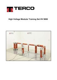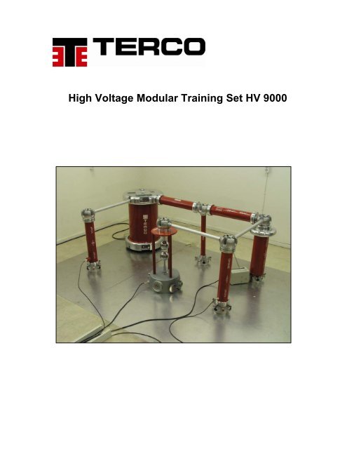
High Voltage Modular Training Set HV 9000 - Terco
High Voltage Modular Training Set HV 9000 - Terco
High Voltage Modular Training Set HV 9000 - Terco

Create successful ePaper yourself
Turn your PDF publications into a flip-book with our unique Google optimized e-Paper software.
<strong>High</strong> <strong>Voltage</strong> <strong>Modular</strong> <strong>Training</strong> <strong>Set</strong> <strong>HV</strong> <strong>9000</strong>
HIGH VOLTAGE MODULAR TRAINING SET<br />
Saving energy is becoming more and more important.<br />
Saving energy can be done by reducing losses. An important factor to reduce losses is to transfer<br />
energy through <strong>High</strong> <strong>Voltage</strong> Transmission lines.<br />
But <strong>High</strong> <strong>Voltage</strong> is also difficult to handle properly, and there<br />
is a lot of technical problems to overcome to make handling of <strong>High</strong> <strong>Voltage</strong> even more efficient.<br />
With TERCO <strong>High</strong> <strong>Voltage</strong> <strong>Modular</strong> <strong>Training</strong> <strong>Set</strong> most of these problems can be studied.<br />
<strong>Terco</strong> <strong>High</strong> <strong>Voltage</strong> Construction Kit <strong>HV</strong> <strong>9000</strong> is based on a system of components made with the<br />
highest precision and can be used to build systems both for teaching and<br />
research as well as for industrial routine and type tests.<br />
The assembly of a required Test <strong>Set</strong> Up is easily done and requires no special toolings.<br />
The system gives values with high accuracy and can even be used for calibration purpose.<br />
General specifications:<br />
<strong>Modular</strong> design make it easy and quick to set up different test circuits, allowing<br />
maximum time for experiments.<br />
Easy to handle due to low weight. All components with exception for the test<br />
transformer can be handled by one person.<br />
Special deigned joints facilitates the connection between components.<br />
Specially designed to minimize partial discharge.<br />
All oil filled components are leak proof.<br />
Easy to follow equipment manuals and experiment manuals.<br />
1
Test room<br />
To have a special test room to house the <strong>HV</strong> <strong>9000</strong> is very important .<br />
This has to be build by the customer in accordance with below guidelines and level of accuracy required<br />
as well as to follow local safety regulations.<br />
For a single stage kit a floor space of 4 x 5 m is recommended, with a height of 2,5-3 m.<br />
Since voltages in excess of 1000 V are generated the safety regulations must be carefully followed.<br />
Fencing and grounding of the Test Room are very important.<br />
Safety equipment<br />
The test area should be enclosed by a metal fence of at least 1.8 m in height and the mesh width not to<br />
exceed 50 mm.<br />
All doors leading into the test room must be equipped with door contacts, which close when the door is<br />
closed. All contacts shall be connected in series and fed to the appropriate sockets on the control desk.<br />
Red and green warning lamps must be installed on all doors leading into the test room. These lamps<br />
should be connected to the control desk.<br />
Earthing (grounding)<br />
Earthing is very important and absolutely necessary for a good test room, and a must for impulse voltage<br />
test equipment.<br />
Connection should be done with low inductance connections ( copper bands 100x0.6mm) which connect<br />
all components of the high-voltage circuit that must be earthed to ONE earth terminal.<br />
Earthing connections should be done without loops. A modern way of doing earthing is to cover the lab<br />
floor with aluminium sheet ( 2mm thickness) which are bolted to the floor and connected internally with<br />
copper band and to earth.<br />
Also the screening surfaces if any, as well as the test objects and the measuring instruments should be<br />
connected to the same earthing point, which should be inside the safety fence and have a lower earthing<br />
resistance than the surrounding building. In any case the earthing resistance should not exceed 2 ohm.<br />
Screening<br />
Screening or shielding as it is also called is used to eliminate all external and internal interference<br />
and can be achieved by building a Faradays cage. The easiest way to obtain this is to hung a close -<br />
meshed metal net on the walls of the laboratory. The unavoidable apertures for power and<br />
communication leads must be blocked for high -frequency currents with low-pass filters. Special<br />
attention must be paid to careful shielding of doors and windows. The floor should be covered with<br />
non-skid sheet metal. The erection of a complete Faradays cage is necessary only when<br />
extremely sensitive partial discharge measurements are intended. Experiments in a high -voltage<br />
practical course can normally be performed without screening.<br />
2
BASIC CONFIGURATIONS FOR TEST SET-UPS<br />
TERCO <strong>HV</strong> <strong>9000</strong><br />
AC TEST DC TEST IMPULSE<br />
Stages 1 2 3 1 2 3 1 2 3<br />
Basic Components<br />
<strong>HV</strong> 9103 Control Desk 1 1 1 1 1 1 1 1 1<br />
<strong>HV</strong> 9105 Test Transformer 100 kV 1 2 3 1 1 1 1 1 1<br />
<strong>HV</strong> 9106 <strong>High</strong> <strong>Voltage</strong> Connection 1 1<br />
<strong>HV</strong> 9107 Discharge Rod 1 1 1 1 1 1 1 1 1<br />
<strong>HV</strong> 9108 Connecting Rod 1 1 3 3 1 4 7<br />
<strong>HV</strong> 9109 Connecting Cup 1 1 3 10 14 7 13 21<br />
<strong>HV</strong> 9110 Floor Pedestal 1 3 5 6 7 8 8<br />
<strong>HV</strong> 9111 <strong>HV</strong> Rectifier 2 4 6 2 2 2<br />
<strong>HV</strong> 9112 Smoothing Capacitor/Impulse capacitor 1 3 5 1 2 3<br />
<strong>HV</strong> 9113 Measuring Resistor 1 2 3 1 1 1<br />
<strong>HV</strong> 9114 Earthing Switch 1 1 1 1 1 1<br />
<strong>HV</strong> 9119 Spacer Tube 2 5 7 5 8 9<br />
<strong>HV</strong> 9120 Load Capacitor 1 2 3<br />
<strong>HV</strong> 9121 Charging Resistor 1 2 3<br />
<strong>HV</strong> 9122 Wave Front Resistor 1 2 3<br />
<strong>HV</strong> 9123 Wave Tail Resistor 1 2 3<br />
<strong>HV</strong> 9124 Insulating Rod 1 8 10 2 5 12<br />
<strong>HV</strong> 9125 Sphere Gap 1 2 3<br />
<strong>HV</strong> 9126 Drive for Sphere Gap 1 1 1<br />
<strong>HV</strong> 9138 Top Electrode 1 11 17 1 1 1<br />
<strong>HV</strong> 9139 Electrode 200 1<br />
<strong>HV</strong> 9140 Electrode 300 1<br />
<strong>HV</strong> 9141 Measuring Capacitor/100 1<br />
<strong>HV</strong> 9142 Measuring Capacitor/200 1<br />
<strong>HV</strong> 9143 Measuring Capacitor/300 1<br />
Measuring and Control Equipment<br />
<strong>HV</strong> 9130 Low <strong>Voltage</strong> Divider 1 2 3<br />
<strong>HV</strong> 9131 Triggering Device 1 1 1<br />
<strong>HV</strong> 9132 Electronic Trigger Sphere 1 1 1<br />
<strong>HV</strong> 9150 AC Peak Voltmeter 1 1 1<br />
<strong>HV</strong> 9151 DC Voltmeter 1 1 1 1 1 1<br />
<strong>HV</strong> 9152 Impulse Volt Meter 1 1 1<br />
Test Apparatus<br />
<strong>HV</strong> 9118 Spacer Bar (for <strong>HV</strong> 9133) 1 1 1<br />
<strong>HV</strong> 9127 Load Resistor 1<br />
<strong>HV</strong> 9133 Measuring Spark Gap 1 1 1<br />
<strong>HV</strong> 9134 Vessel for Vacuum/ and Pressure 1 1 1<br />
<strong>HV</strong> 9135 Corona Cage 1 1<br />
<strong>HV</strong> 9137 Oil Testing Cup 1 1<br />
<strong>HV</strong> 9144 Compressed Gas Capacitor 1<br />
<strong>HV</strong> 9146 Capacitor Coupling 1<br />
<strong>HV</strong> 9153 Partial Discharge Meter 1<br />
3
TEST SET-UPS<br />
AC <strong>Voltage</strong> — Typical Configurations<br />
Single-stage Two-stage Three-stage<br />
Rated no load voltage 100 Rated no load voltage 200 Rated no load voltage 300<br />
kV (rms) kV (rms) kV (rms)<br />
Output (kVA) : Output (kVA) : Output (kVA) :<br />
Continuous 5 Continuous 5 Continuous 5<br />
1 Hr. on 10 1 Hr. on 10 1 Hr. on 10<br />
Rated current (mA) 50 Rated current (mA) 25 Rated current (mA) 16<br />
100 50 32<br />
Impedance voltage 4 Impedance voltage 7 Impedance voltage 11<br />
(%) Approx. (%) Approx. (%) Approx.<br />
Frequency (Hz) 50/60 Frequency (Hz) 50/60 Frequency (Hz) 50/60<br />
4
TEST SET-UPS<br />
DC <strong>Voltage</strong> — Typical Configurations<br />
Single-stage Two-stage Three-stage<br />
Rated no load voltage kV 140 Rated no load voltage kV 280 Rated no load voltage kV 400<br />
Rated current (mA) 13 Rated current (mA) 10 Rated current (mA) 7.5<br />
5
TEST SET-UPS<br />
Impulse <strong>Voltage</strong> — Typical Configurations<br />
Single-stage Two-stage Three-stage<br />
Rated DC charging voltage 140 kV Rated DC charging voltage 280 kV Rated DC charging voltage 420 kV<br />
Maximum stored energy with:<br />
1. CS 25 (25 nF)<br />
2. CS 50 (50 nF)<br />
3. CS 100 (100 nF)<br />
245 J<br />
490 J<br />
980 J<br />
Maximum stored energy with:<br />
1. CS 25 (25 nF)<br />
2. CS 50 (50 nF)<br />
3. CS 100 (100 nF)<br />
490 J<br />
980 J<br />
1.96 kJ<br />
Maximum stored energy with:<br />
1. CS 25 (25 nF)<br />
2. CS 50 (50 nF)<br />
3. CS 100 (100 nF)<br />
735J<br />
1.47 kJ<br />
2.94 kJ<br />
<strong>Voltage</strong> efficiancy (Approx) 92 % <strong>Voltage</strong> efficiancy (Approx) 92 % <strong>Voltage</strong> efficiancy (Approx) 92 %<br />
6
<strong>HV</strong> 9103 Control Desk<br />
Technical data<br />
Supply voltage:<br />
Regulating transformer:<br />
Regulating <strong>Voltage</strong>:<br />
Output:<br />
Size:<br />
Weight:<br />
230 V 50/60 Hz<br />
5kVA Continuous rating<br />
driven by 24 V DC geared<br />
motor drive.<br />
220V/0-230 V<br />
5kVA Continuous<br />
10 kVA (short time duty 2 min.)<br />
1220x105x800mm (h,w,d)<br />
275 kg<br />
This control desk is used to control and operate high voltage AC/DC/Impulse test equipment.<br />
The desk contains operating and signal elements for the control circuit of the test equipment for warning<br />
and safety<br />
The control desk is made to house the measuring instruments ( Peak, Impulse and DC Voltmeter) and<br />
also the Trigger Device.<br />
Its fabricated of steel and stands on four wheels.<br />
<strong>HV</strong> 9105 Test Transformer<br />
Technical data<br />
Ratio:<br />
Rated cont. current:<br />
Output:<br />
Impedance voltage:<br />
Frequency:<br />
Partial discharge level:<br />
Dimensions<br />
Height:<br />
Diameter:<br />
Weight:<br />
2x220V/100kV/220V<br />
2x11,4A/50mA/15.2A<br />
Continuous.<br />
5 kVA, 10kVA for 60 min. outputs for AC.<br />
4% approx.<br />
50Hz or 60 Hz<br />
at 100 kV< 3pC.<br />
770 mm<br />
550 mm<br />
215 kg<br />
Application.<br />
Test transformer with coupling winding for cascade connection to produce AC, DC and Impulse voltages.<br />
The transformer consist of three windings with insulating shell and top and bottom corona free aluminium<br />
shielding electrodes.<br />
The insulation cylinder is made of epoxy resin with glass fibre reinforcement and coated with anti tracking<br />
varnish.<br />
The exciter winding is divided into two groups viz. 100 %voltage when connected in parallel and 50%<br />
output voltage at rated current when connected in parallel and 50% output voltage at rated current when<br />
connected in series.<br />
The coil is vacuum impregnated and insulated with high quality grade transformer oil.<br />
The third winding known as “Coupler Winding” is provided for further cascade connection.<br />
7
MEASURING & CONTROL EQUIPMENTS<br />
Technical data<br />
Application<br />
<strong>HV</strong> 9150<br />
Peak Voltmeter (Digital Display)<br />
Supply voltage : 220 V 50 Hz<br />
Measurement of AC voltage Peak. For<br />
Measuring Range :<br />
100-1000 Û / √2 kV<br />
connection to the measuring capacitor,<br />
the compressed gas capacitor or the<br />
Weight : 2.8 kg<br />
Coupling capacitor<br />
Dimensions : 142 x 173 x 245<br />
( W X H X D)<br />
<strong>HV</strong> 9152<br />
Impulse Voltmeter (Digital Display)<br />
Supply voltage : 220 V 50 Hz<br />
Measurement of the Impulse <strong>Voltage</strong> peak. For<br />
Measuring Range :<br />
100-1000kV<br />
Connection to the load capacitor<br />
Weight : 3.4 kg<br />
Dimensions : 142 x 173 x 245<br />
( W X H X D)<br />
<strong>HV</strong> 9151<br />
DC Voltmeter (Digital Display)<br />
Supply voltage : 220 V 50 Hz<br />
Measurement of the DC <strong>Voltage</strong>. For<br />
Measuring Range :<br />
140kV/280kV/400kV<br />
Connection to the Measuring Resistor<br />
Weight : 3.0 kg<br />
Dimensions : 142 x 173 x 245<br />
( W X H X D)<br />
<strong>HV</strong> 9131<br />
Trigger Device<br />
Supply voltage : 220 V 50 Hz<br />
Weight<br />
Dimensions<br />
: 3.7 kg<br />
142 x 173 x 245<br />
( W X H X D)<br />
for Triggering the impulse voltage generator<br />
impulse voltage oscilloscope and chopping<br />
spark gap.<br />
The trigger impulse is transferred to the<br />
high voltage sphere by means of a fibre<br />
optics cable . The impulse is<br />
amplified in the electronic trigger sphere<br />
<strong>HV</strong> 9130<br />
Low <strong>Voltage</strong> Divider<br />
Measuring Ranges<br />
(Optional)<br />
450 kV<br />
300 kV<br />
150 kV<br />
75 kV<br />
37.5 kV<br />
Incorporates the Low voltage capacitors and the<br />
75 ohm cable adapter It is plugged in to the HF -<br />
Socket of the load capacitor and connection<br />
to the Impulse <strong>Voltage</strong> meter by means<br />
of co-axial cable.<br />
<strong>HV</strong> 9132<br />
Electronic trigger sphere<br />
Diameter : 100 mm<br />
Weight : 0.7 kg<br />
Suitable for use with the sphere gaps and<br />
measuring spark gaps . In conjunction with<br />
the triggering device . The impulse Volt<br />
Generator can be triggered and the voltage be<br />
chopped at a pre set instant with fibre optic<br />
cable 10 mtr long<br />
8
BASIC ELEMENTS FOR AC/DC/IMPULSE SET-UPS<br />
Capacitors<br />
Technical data<br />
<strong>HV</strong> 9112<br />
Impulse Capacitor<br />
DC and Impulse voltages : 140 kV<br />
Capacitance<br />
:25 nF<br />
Weight<br />
:18 kg<br />
Application<br />
Impulse capacitor for generation of<br />
impulse voltages. It can also be used<br />
as smoothing capacitor in DC voltage<br />
generation.<br />
<strong>HV</strong> 9112-50<br />
Impulse Capacitor<br />
DC and Impulse voltages : 140 kV<br />
Capacitance<br />
:50 nF<br />
Weight<br />
:38 kg<br />
Impulse capacitor for generation of<br />
impulse voltages. It can also be used<br />
as smoothing capacitor in DC voltage<br />
generation.<br />
<strong>HV</strong> 9112-100<br />
Impulse Capacitor<br />
DC and Impulse voltages : 140 kV<br />
Capacitance<br />
:100 nF<br />
Weight<br />
:60 kg<br />
Impulse capacitor for generation of<br />
impulse voltages. It can also be used<br />
as smoothing capacitor in DC voltage<br />
generation.<br />
<strong>HV</strong> 9120<br />
Load Capacitor<br />
DC and Impulse voltages<br />
:140 kV<br />
Capacitance<br />
:1.2 nF<br />
Weight<br />
:10 kg<br />
Load capacitor and high voltage<br />
divider capacitor for measurement<br />
impulse voltages.<br />
of<br />
<strong>HV</strong> 9141<br />
AC voltages<br />
Capacitance<br />
Weight<br />
Measuring Capacitor<br />
: 100 kV<br />
:100 pF<br />
:10 kg<br />
<strong>High</strong> voltage divider capacitor<br />
measurement of AC voltages.<br />
for<br />
<strong>HV</strong> 9142<br />
AC voltages<br />
Capacitance<br />
Weight<br />
Measuring Capacitor<br />
: 200 kV<br />
: 100 pF<br />
: (Approx.) 75 kg<br />
<strong>High</strong> voltage divider capacitor<br />
measurement of AC voltages.<br />
for<br />
<strong>HV</strong> 9143<br />
AC voltages<br />
Capacitance<br />
Weight<br />
Measuring Capacitor<br />
:300 kV<br />
: 100 pF<br />
: (Approx.) 125 kg<br />
<strong>High</strong> voltage divider capacitor for<br />
measurement of AC voltages.<br />
9
<strong>HV</strong> 9106<br />
<strong>HV</strong> Connection<br />
Length<br />
: Approx. 0.7 m for 200 kV<br />
Approx. 2.2 m for 300 kV<br />
Flexible metal connection with<br />
connector for the test transformer<br />
and connecting Cup. For connection of<br />
a multi-stage AC voltage test equipment<br />
with the test transformer.<br />
<strong>HV</strong> 9114<br />
Grounding Switch, Electrically Operated<br />
Impulse <strong>Voltage</strong> :<br />
140 kV<br />
DC <strong>Voltage</strong> :<br />
140 kV<br />
For grounding the high voltage<br />
construction kit when de-energized.<br />
Service <strong>Voltage</strong> :<br />
24 V, 50 / 60 Hz<br />
Weight<br />
6.5 kg<br />
<strong>HV</strong> 9138<br />
Diameter<br />
Weight<br />
Electrode<br />
300 mm<br />
2 kg<br />
Serves as termination in conjunction with<br />
Grounding switch for safety grounding.<br />
Also serves as corona free electrode.<br />
<strong>HV</strong> 9107<br />
Discharge Rod<br />
Length<br />
2.5 m<br />
Discharge Resistance<br />
Weight<br />
100 Ω<br />
1.5 kg<br />
For Manual discharging of<br />
equipment components.<br />
<strong>HV</strong> 9109<br />
Aluminum cast<br />
Weight<br />
Connecting cup<br />
2.5 kg<br />
Conductive Element: four elements<br />
can be inserted in horizontal position<br />
and two in vertical position.<br />
<strong>HV</strong> 9110<br />
Floor Pedestal<br />
Aluminum cast<br />
Weight<br />
1 kg<br />
Conductive Element: for mounting<br />
up to four Spacer bars horizontally<br />
and supporting one Component vertically.<br />
<strong>HV</strong> 9108<br />
Connecting Rod<br />
Aluminum tube<br />
Weight<br />
1 kg<br />
Conductive connection element.<br />
<strong>HV</strong> 9119<br />
Spacer tube<br />
Aluminum tube<br />
Weight<br />
1 kg<br />
Mechanical and electrical connection<br />
on ground level when inserted into floor<br />
pedestal<br />
11
Different Experiment setups and Safety Net Installation<br />
Measurement of flashover<br />
Measurement of flashover voltage in vacuum<br />
and under pressure<br />
Impulse setup<br />
Demonstrating easy assembly<br />
Installation of Safety Net<br />
13
List of experiments<br />
1. Generation and Measurement of Alternating <strong>Voltage</strong><br />
2. Generation and Measurement of Direct <strong>Voltage</strong>s<br />
i.) Load characteristics of Rectifiers<br />
ii.) Measurement of Ripple Factor<br />
3. Generation and Measurement of Direct <strong>Voltage</strong>s II<br />
i.) Greinacher <strong>Voltage</strong> Doubler Circuit<br />
ii.) Polarity effect and Insulating screens<br />
4. Generation of Impulse <strong>Voltage</strong>s<br />
5. Measurement of Impulse <strong>Voltage</strong>s<br />
6. Power Frequency and Impulse <strong>Voltage</strong> Tests on Power Transformer<br />
7. Experiment on Insulating Liquids.<br />
i.) DC Conductivity<br />
ii.) Measurement of Tan delta and Capacitance<br />
8. Experiment on Solid and Insulating Liquids<br />
i.) Fibre- Bridge breakdown in Insulating Oil<br />
ii.) Breakdown Strength of Hard Board Plate<br />
9. Experiment on Partial Discharge and Corona<br />
i.) Partial Discharges at Needle Electrode in air<br />
ii.) Measurement in Corona cage<br />
10. Experiment on PD and Gliding Discharges<br />
i.) PD Measurement in <strong>High</strong> <strong>Voltage</strong> Insulation<br />
ii.) Measurement of Onset <strong>Voltage</strong>s of Gliding Discharge<br />
11. Break down of Gases<br />
14