Scan Lab System Electrical Machines Laboratory - Terco
Scan Lab System Electrical Machines Laboratory - Terco
Scan Lab System Electrical Machines Laboratory - Terco

You also want an ePaper? Increase the reach of your titles
YUMPU automatically turns print PDFs into web optimized ePapers that Google loves.
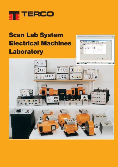
<strong>Scan</strong> <strong>Lab</strong> <strong>System</strong><br />
<strong>Electrical</strong> <strong>Machines</strong><br />
<strong>Lab</strong>oratory
TERCO SCAN LAB SYSTEM<br />
For more than 40 years <strong>Terco</strong> has developed and sold electrical machines for technical education,<br />
and our systems are installed in schools all over the world.<br />
During the development of the <strong>Scan</strong> <strong>Lab</strong> <strong>System</strong>, we have put together all our expertise and<br />
experience and built the most complete system on the market.<br />
<strong>Scan</strong> <strong>Lab</strong> is completely modular, and the various modules can be bought separately and<br />
integrated as the demand arises. This enhances the use of <strong>Scan</strong> <strong>Lab</strong> and makes it flexible and<br />
economical.<br />
All the electrical machines as well as the power electronics have been chosen to take industrial<br />
standards into consideration. <strong>Terco</strong> <strong>Scan</strong> <strong>Lab</strong> is accurate. Too small electrical machines give<br />
unrealistic measuring values. We have carefully considered this by optimizing the winding data of<br />
the machines and by choosing an effect of approx. 400 W. The losses in percent for this size of<br />
machines, are not especially high compared with the total power.<br />
SAFETY<br />
All electric wiring is galvanically isolated and protected in case of wrong doing. The banana<br />
terminals are of safety type.<br />
SERVICE<br />
<strong>Terco</strong> have manufactured thousands of electrical machine systems for training purposes since<br />
the early sixties, systems, which have been delivered to countries all over the world. Most of the<br />
systems are still in operation. In spite of this fact it is not very often we have to carry out service<br />
or repair. However, should the need occur, our well trained service personnel will always be there<br />
to support you.<br />
QUALITY CONTROL<br />
All equipment is carefully checked and after approval provided with TERCO's well known quality<br />
mark, a sign of safety and security for our customers.<br />
TRAINING COURSES<br />
<strong>Terco</strong> organises training courses for most of the equipment both in house or at the customer's<br />
own site. Most of our courses are especially designed to teach you how to handle the equipment<br />
in the most efficient way. These courses are often a very good investment.<br />
DOCUMENTATION<br />
Every shipment includes comprehensive documentation including course literature and a teacher<br />
guide and manual.
<strong>Scan</strong> <strong>Lab</strong> <strong>System</strong> – <strong>Electrical</strong> <strong>Machines</strong> <strong>Lab</strong>oratory<br />
Contents<br />
Page<br />
<strong>Terco</strong> <strong>Scan</strong> <strong>Lab</strong> <strong>System</strong> 2<br />
Brakes & Torque-measurements 4–5<br />
Test <strong>Machines</strong> 6–8<br />
Power Supplies 9<br />
Load Units 10<br />
Phasing Instruments 11<br />
Accessories 12–13<br />
Switch Panels 13<br />
<strong>Lab</strong>oratory Flexes and Flex Stand 13<br />
<strong>Electrical</strong> Measuring Instruments 14–17<br />
Power Electronics and Drives 18–21<br />
Transformers 21<br />
Measuring and Data Acquisition with PC 22–23<br />
Equipment Lists 24–25<br />
Sectioned Motors 26<br />
Experiment Manuals 27<br />
Compact Drive 28–29<br />
<strong>Terco</strong> <strong>Electrical</strong> Machine <strong>System</strong>s 30–31<br />
<strong>Lab</strong>oratory Lay-out 32<br />
<strong>Electrical</strong> Power Distribution <strong>System</strong> 33<br />
Guarantee & Terms 34<br />
<strong>Terco</strong> reserves the right to make changes in the design and modifications or improvements of the products<br />
at any time without incurring any obligations.<br />
3
<strong>Scan</strong> <strong>Lab</strong> <strong>System</strong> – <strong>Electrical</strong> <strong>Machines</strong> <strong>Lab</strong>oratory<br />
Brakes & Torque-measurements<br />
The measurement of the torque is vital when studying electrical machines. Specially important is to have high accuracy<br />
from zero revolutions to the top speed. <strong>Terco</strong> has developed two completely new measuring systems. One is an electric<br />
brake together with a DC-machine for simpler measurements, and one is a more advanced system with possibility of<br />
monitoring and control with PC.<br />
SM 2641<br />
SM 2643<br />
SM<br />
2613<br />
SM<br />
2613<br />
MV 1052<br />
SM 2640<br />
MV 1052 Torque Measuring Unit<br />
MV 1052 is a modern torque meter based on the latest computer technology. It comprises an opto electronic transducer<br />
and an electronic control and display unit. The transducer consists of a torsion shaft. The torsion is measured optically<br />
and is converted into torque. The speed is also measured and with a very high accuracy. The torquemeter works down to<br />
a relatively low speed. Torque, power and speed can be read easily on the display of the control units digital instruments.<br />
From the control unit the field windings of the test motors can be controlled via a potentiometer on the front, or by remote<br />
control. On the backpanel, there are outputs for plotter and computer.<br />
Technical Data<br />
Torque<br />
Max mech load<br />
Shaftpower<br />
Speed<br />
Brake control<br />
Output for plotter/PC<br />
Output for plotter/PC<br />
Speed<br />
Speed<br />
Torque<br />
Torque<br />
Shaftpower<br />
Shaftpower<br />
Power supply<br />
Shaft height<br />
Power supply<br />
0-10 Nm<br />
25 Nm<br />
2 kW<br />
120-4000 rpm<br />
Manually via pot. on front panel<br />
0-195 V DC, 2 A<br />
Remote with PC through<br />
5 V terminal<br />
at 2000 rpm<br />
5 V at 2000 rpm<br />
at 10 Nm<br />
5 V at 10 Nm<br />
at kW<br />
5 V at 2 kW<br />
220-240 V, 1-phase, 50-60 Hz<br />
100 mm<br />
220-240 V, 1-phase, 50-60 Hz<br />
Dimensions<br />
Accuracy<br />
Transducer Torque ≤ 300 2% x 200 x 150 mm<br />
Weight Power ≤ 4 2% kg<br />
Control Speed unit<br />
≤ 250 1% x 340 x 150 mm<br />
Weight<br />
5 kg<br />
Dimensions<br />
Transducer<br />
300 x 200 x 150 mm<br />
Weight<br />
4 kg<br />
Control unit<br />
250 x 340 x 150 mm<br />
Weight<br />
5 kg<br />
The same equipment is also available for our Classic 1 kW <strong>Electrical</strong> <strong>Machines</strong> with shaft height 162 mm.<br />
It is then called MV 1051.<br />
4
<strong>Scan</strong> <strong>Lab</strong> <strong>System</strong> – <strong>Electrical</strong> <strong>Machines</strong> <strong>Lab</strong>oratory<br />
SM 2641<br />
SM 2643<br />
SM 2612<br />
SM 2640<br />
SM 2671<br />
SM 2671 Brake Control Unit<br />
The SM 2671 Brake Control Unit is designed to operate with one <strong>Terco</strong> DC-Machine + one <strong>Terco</strong> DC-Tacho Generator<br />
(e.g. SM 2641 + SM 2612). The Control Unit is trimmed against the chosen machine and tacho generator to make it<br />
possible to calculate the air gap torque in the DC-machine. With a tacho signal also speed and shaft power is calculated.<br />
The result is displayed by three LCD-instruments.<br />
Braking force is controlled by a potentiometer on the front.<br />
To facilitate full braking force at high, medium, low speeds and close to standstill, the braking resistor can be configurated<br />
by two jumpers placed in the front plate. The braking resistors are cooled by a built-in fan.<br />
SM 2671 can also be trimmed to already existing DC-machine and tachometer generator.<br />
Technical specifications<br />
Factory trimmings<br />
Against specified DC-machine and tacho<br />
Braking Power<br />
Max 1500 W 30 min.<br />
Speed indication<br />
0-4000 rpm<br />
Torque indication<br />
0-12 Nm<br />
Power indication<br />
0-2000 W<br />
Accuracy speed 0.5 %<br />
Accuracy Nm and W<br />
5 % or better<br />
Machine connections<br />
Four 4 mm safety terminals<br />
Tacho connections<br />
Two 4 mm terminals<br />
Size W x D x H<br />
480 x 330 x 210 mm (inclined front)<br />
Power supply<br />
220-240 V, 1-phase, 50-60 Hz<br />
Weight approx.<br />
9 kg<br />
Other input voltages available on request.<br />
5
<strong>Scan</strong> <strong>Lab</strong> <strong>System</strong> – <strong>Electrical</strong> <strong>Machines</strong> <strong>Lab</strong>oratory<br />
Rotating machines – Motors & Generators<br />
The size of the machines is carefully chosen to optimise price and performance. In our opinion 400 watt machines are<br />
ideal. If the machines are smaller the performance of the machines will not be representative. The losses in percent are<br />
still not especially high compared with the total power.<br />
All machines have shaft height of 100 mm, and are provided with clutch, terminalbox with mimic diagram, 4 mm safety<br />
terminals and a baseplate enabling stepless fastening on the machine bed.<br />
Temperature safety class: vary between B to F (130-155°C).<br />
<strong>Machines</strong> running as generators and motors<br />
SM 2641 DC Machine with separate excitation winding<br />
This DC machine has an open shunt winding, enabling SM 2641 to be<br />
connected either for shunt excitation or for separate excitation, both as<br />
motor and generator.<br />
SM 2641 also has interpoles which improves the characteristics of the<br />
machine. It is ideal to use together with DC-converters.<br />
Technical Data<br />
Power<br />
Armature voltage<br />
Armature current<br />
Excitation<br />
Temperature class<br />
Dimension<br />
Weight<br />
400 W at 1500 rpm/Max 3000 rpm<br />
0-300 V DC<br />
3.5 A DC<br />
190 V / 0.2 A<br />
F (155°C)<br />
400 x 250 x 200 mm<br />
17 kg<br />
SM 2643 DC Compound Machine<br />
This machine has a shunt and a series winding, and can be connected<br />
as shunt, series and compound motor or generator. It also has<br />
interpoles which improves the performance of the machine.<br />
Technical Data<br />
Power:<br />
Motor<br />
Generator<br />
Rotor<br />
Excitation<br />
Temperature class<br />
Dimension<br />
Weight<br />
400 W at 1500 rpm<br />
400 W at 1800 rpm<br />
160 V 3.7 A DC<br />
190 V 0.2 A DC<br />
F (155°C)<br />
400 x 250 x 200 mm<br />
16 kg<br />
SM 2646 DC Series Motor<br />
400 W att 2200 rpm, 3.7 A.<br />
Same design as SM 2643 above.<br />
SM 2649 Flywheel<br />
This is used in retardation tests for determining total friction losses, iron<br />
losses and short circuit losses at different excitation levels. The Flywheel<br />
is dynamically balanced and has a protective casing.<br />
Technical Data<br />
Dimensions<br />
Weight<br />
1150 x 200 x 70 mm<br />
10 kg<br />
6
<strong>Scan</strong> <strong>Lab</strong> <strong>System</strong> – <strong>Electrical</strong> <strong>Machines</strong> <strong>Lab</strong>oratory<br />
SM 2645 Slipring Synchronous/Asynchronous Machine<br />
This is a universal slip ring 3-phase AC machine which can run as a<br />
slip ring asynchronous motor, synchronous motor and synchronous<br />
generator. When running in synchronous mode the rotor will be excitated<br />
to 60 V / 3.5 A DC. During max. 30 min this can be increased to 5.5 A to<br />
show important parameters.<br />
Technical Data<br />
Power<br />
500 W<br />
Speed<br />
1400 rpm / 50 Hz<br />
1700 rpm / 60 Hz<br />
Cos phi 0.8<br />
Stator voltage<br />
3 x 230 V AC<br />
Stator current<br />
2.3 A<br />
Rotor data<br />
3 x 230 V AC, 2.3 A (nom)<br />
Rotor excitation<br />
60 V DC, 5.5 A (max)<br />
Temperature class<br />
F (155°C)<br />
Dimension<br />
400 x 250 x 200 mm<br />
Weight<br />
15 kg<br />
<strong>Machines</strong> operated mainly as motors<br />
SM 2644 Induction Motor Squirrel Cage<br />
This is a normal 3 phase squirrel cage asynchronous motor with 4 poles.<br />
With this motor not only the normal testing can be done, it is also suitable<br />
to use together with a frequency converter.<br />
Technical Data<br />
Power<br />
370 W<br />
Speed<br />
1400 rpm / 50 Hz<br />
1700 rpm / 60 Hz<br />
Cos phi 0.7<br />
Voltage<br />
230 V / 400 V<br />
Current<br />
2.1 / 1.2 A<br />
Dimension<br />
270 x 230 x 200 mm<br />
Weight<br />
7 kg<br />
SM 2647 Reluctance Motor<br />
400 W at 1500 rpm. Same design as 2644 above.<br />
SM 2648 Universal Motor<br />
This motor is very useful. It can be connected both to AC and DC power.<br />
The rotor is, via brushes and commutators, connected in series with the<br />
field winding.<br />
Technical Data<br />
Power<br />
370 W DC, 250 W AC<br />
Speed<br />
1500 rpm / 50 Hz<br />
Voltage<br />
230 V AC / DC<br />
Current<br />
2.5 A DC, 3.9 A AC<br />
Dimension<br />
300 x 250 x 200 mm<br />
Weight<br />
14 kg<br />
SM 2640 Machine Bed<br />
The machine bed is designed to house three<br />
machine modules in the SM 2600 module<br />
group. The bed is equipped with rubber feet<br />
and handles.<br />
Technical Data<br />
Dimensions 1150 x 200 x 70 mm<br />
Weight 10 kg<br />
7
<strong>Scan</strong> <strong>Lab</strong> <strong>System</strong> – <strong>Electrical</strong> <strong>Machines</strong> <strong>Lab</strong>oratory<br />
SM 2683 Dahlander Motor<br />
In this motor the windings are arranged in such a way that by using different<br />
connections the motor can run at two different speeds. Change of speed can<br />
be done with contactors or by a camswitch (SM 2694).<br />
Technical Data<br />
Power 450 / 300 W<br />
Speed 1400 / 2700 rpm / 50 Hz<br />
1650 / 3200 rpm / 60 Hz<br />
Voltage D / YY 230 V 3-ph., 50-60 Hz<br />
Current<br />
Dimension<br />
Weight<br />
2.1 / 1.6 A<br />
300 x 230 x 200 mm<br />
9 kg<br />
SM 2684 1-Phase Induction Motor with Start<br />
and Run Capacitor<br />
This motor is equipped with two capacitors. The start capacitor is disconnected<br />
at halfspeed, but allows for a higher start torque, whilst the run<br />
capacitor is continuously connected and gives the motor good working<br />
torque.<br />
Technical Data<br />
Power 370 W<br />
Speed 1400 rpm / 50Hz<br />
1670 rpm / 60 Hz<br />
Voltage 230 V 1-phase, 50-60 Hz<br />
Current<br />
Dimension<br />
Weight<br />
2.9 A<br />
300 x 290 x 200 mm<br />
10 kg<br />
SM 2685 1-Phase Induction Motor with Start Capacitor<br />
This motor is equipped with operating winding and start winding. For higher<br />
start torque the influence of the start winding is improved by use of a<br />
capacitor which is disconnected through a centrifugal switch when working<br />
speed has been reached.<br />
Technical Data<br />
Power 370 W<br />
Speed 1400 rpm / 50 Hz<br />
1670 rpm / 60 Hz<br />
Voltage 230 V 1-phase, 50-60 Hz<br />
Current<br />
Dimension<br />
Weight<br />
4.4 A<br />
300 x 290 x 200 mm<br />
10 kg<br />
SM 2686 Split - Phase Motor<br />
A single phase motor having 2 windings. The start winding is disconnected<br />
by means of a centrifugal switch when the motor has reached a fraction of<br />
full speed.<br />
Technical Data<br />
Power 250 W<br />
Speed 1400 rpm / 50 Hz<br />
1700 rpm / 60 Hz<br />
Voltage 230 V 1-phase, 50-60 Hz<br />
Current<br />
Dimension<br />
Weight<br />
3.1 A<br />
300 x 250 x 200 mm<br />
13 kg<br />
SM 2688 Two Speed Induction Motor Squirrel Cage<br />
This motor unlike SM 2683 has 2 separate windings for high and low speed.<br />
Technical Data<br />
Power 350 / 300 W<br />
Speed 1400 / 900 rpm / 50 Hz<br />
1700 / 1100 rpm / 60 Hz<br />
Voltage 230 V 3-phase, 50-60 Hz<br />
Current<br />
Dimension<br />
Weight<br />
2.4/2.3 A<br />
300 x 230 x 200 mm<br />
9 kg<br />
8
<strong>Scan</strong> <strong>Lab</strong> <strong>System</strong> – <strong>Electrical</strong> <strong>Machines</strong> <strong>Lab</strong>oratory<br />
Power Supplies<br />
Power supply is essential for all excercises with electrical machines. The <strong>Scan</strong> <strong>Lab</strong> power supply is designed in such<br />
a way that it can be used whenever power is needed within the school.<br />
The Power Panel is made as a seperate module which increases the flexiblility of <strong>Scan</strong> <strong>Lab</strong>.<br />
SM 2631 Power Supply Unit<br />
Comprises one isolated 3-phase main transformer and<br />
one variac transformer. The unit is mobil and connected<br />
through a multipole cable to Terminal Unit SM 2635.<br />
The voltage is varied by a knob on top of the unit. The<br />
starter is controlled from the Terminal Unit. Different AC<br />
and DC voltages are available from the Terminal Unit<br />
SM 2635 (see below).<br />
Technical Data<br />
Primary supply<br />
(changeable)<br />
Primary fuses<br />
Output connector<br />
Connection<br />
Dimensions<br />
Weight<br />
3 x 400 V, 50-60 Hz<br />
3 x 230 V, 50-60 Hz<br />
3 x 4 A slow<br />
16-pole, 16 A<br />
European connector 16 A<br />
350 x 300 x 650 mm<br />
50 kg<br />
Note: The Power Supply Unit SM 2631 and the<br />
Terminal Unit SM 2635 are part of each other and do<br />
not work separately.<br />
SM 2635 Terminal Unit<br />
The Terminal Unit is connected to the Power Supply Unit<br />
SM 2631 by a multilead power receptacle. Since all heavy<br />
and bulky equipment, which normally goes together with<br />
a multifunction power supply, is placed in the Power<br />
Supply Unit, the Terminal Unit, which is quite light, can<br />
easily be placed on the laboratory table, beside, below or<br />
on top of other equipment close to the experimental units.<br />
The unit includes also a combined AC/DC machine starter.<br />
Technical Data<br />
Fixed 3-phase voltage<br />
Variable 3-phase voltage<br />
Variable DC-voltage<br />
Fixed DC-voltage<br />
3 x 230 V with neutral,<br />
4 A, F fuses<br />
3 x 0-230 V with neutral,<br />
4 A, F fuses<br />
0-300 V<br />
6 A, F indirectly fused<br />
190 V<br />
2 A, F fuse<br />
Electronically controlled (phase)<br />
DC-voltage:<br />
0-190 V, 2 A, F fuse<br />
Electronically controlled (PWM) DC-voltage for excitation of<br />
AC-machine SM 2645 operating as synchronous machine:<br />
Output DC<br />
0-60 V, 5 A<br />
Fusing<br />
6 A, FF<br />
R-starter group<br />
3 steps + direct for DC/AC<br />
slipring machines<br />
Dimension<br />
490 x 135 x 340 mm<br />
Weight<br />
10 kg<br />
9
<strong>Scan</strong> <strong>Lab</strong> <strong>System</strong> – <strong>Electrical</strong> <strong>Machines</strong> <strong>Lab</strong>oratory<br />
Load Units<br />
The loads are suitable to use with the <strong>Scan</strong> <strong>Lab</strong> <strong>System</strong> and other lab. experiments where these type of loads fit in.<br />
SM 2676 Load Resistor Module<br />
Load resistor SM 2676 contains 6 separate continuously variable resistors<br />
with individual terminals. To be used for variable 3-phase , 1-phase or<br />
DC loads.<br />
Technical Data<br />
Resistance<br />
Rated current<br />
Max. cont. load<br />
Dimension<br />
Weight<br />
6 x 0-100 ohm<br />
6 x 1.8 A<br />
1.9 kW<br />
450 x 280 x 280 mm<br />
15 kg<br />
SM 2672 Capacitive Load Module<br />
This is a 3-phase capacitive load variable in 6 steps.<br />
The unit can be used both for three and single phase.<br />
Technical Data<br />
Rated power<br />
2.7 kVAr<br />
Capacitance 3 x 48 µF<br />
0 + 6 steps<br />
Voltage<br />
250 V / phase AC<br />
Dimension<br />
250 x 340 x 150 mm<br />
Weight<br />
3.5 kg<br />
SM 2674 Inductive Load Module<br />
This is a 3-phase inductive load variable in 6 steps. The unit can be used<br />
both for three and single phase operation.<br />
Technical Data<br />
Rated power<br />
Inductance<br />
Voltage<br />
Dimension<br />
Weight<br />
0.9 kVar<br />
0.2-1.5 H / phase<br />
0 + 6 steps<br />
140 V / phase<br />
250 x 340 x 150 mm<br />
14 kg<br />
SM 2637 VAr Controller<br />
This unit is designed to be used together with <strong>Terco</strong> synchronous<br />
machines rating 1-2 kVAr when these are used as VAr compensating<br />
units or run as motors / generators with voltage stabilising ability.<br />
Specifications<br />
Voltage feedback from controlled<br />
network<br />
Field winding controlled voltage<br />
Field winding controlled current<br />
Supply voltage (1-phase)<br />
Dim W x H x D<br />
Weight (approx.)<br />
3-ph 220-400 V<br />
0-170 V DC<br />
0-3 A (max) DC<br />
220-240 V AC 50 / 60 Hz<br />
250 x 340 x 150 mm<br />
7 kg<br />
10
<strong>Scan</strong> <strong>Lab</strong> <strong>System</strong> – <strong>Electrical</strong> <strong>Machines</strong> <strong>Lab</strong>oratory<br />
Phasing Instruments<br />
SM 2670 Synchronizing Device<br />
The equipment includes 1 zero voltmeter, 1 circuit breaker, 3 signal<br />
lamps and terminal bolts.<br />
With SM 2670 it is an easy matter to synchronise synchronous machines<br />
to networks or to an other alternator.<br />
General Data<br />
Zero Voltmeter<br />
2 x 140 V<br />
Circuit Breaker<br />
16 A 500 V<br />
Synch. Lamps<br />
130 V with resistor<br />
Supply Voltage<br />
220-240 / 127-140 V, 50-60 Hz<br />
Dimensions<br />
315 x 240 x 90 mm<br />
Weight<br />
3 kg<br />
Other voltages can be supplied on request.<br />
MV 1909 Synchronizing Unit<br />
The unit includes 1 dual voltmeter, 1 dual frequency meter and a<br />
synchroscope. To switch the synchronised supplies together, load switch<br />
SM 2690 is required.<br />
General Data MV 1909-235 MV 1909-236<br />
Dual Voltmeter 2 x 250 V 2 x 250 V<br />
Dual Frequency Meter 44-56 Hz 54-66 Hz<br />
Synchroscope<br />
Supply Voltage 220-240 V / 220-240 V /<br />
127-140 V 127-140 V<br />
Dimensions<br />
350 x 140 x 160 mm<br />
Weight<br />
6.5 kg<br />
Phase Cop 2 Phase Sequence Indicator<br />
Tester for determining the direction of rotation or phase sequence in<br />
3-phase systems.<br />
- 3 LEDs indicate whether or not the 3-phase conductors are live<br />
- Very large voltage and frequency range<br />
- Simple operation<br />
- Rugged design<br />
- Permanently connected cables with contact-protected connector plugs,<br />
three plug-on test probes and one plug-on alligator clip<br />
General Data<br />
Voltage range<br />
Frequency<br />
Dimensions<br />
Weight<br />
90-660 V<br />
45-1000 Hz<br />
70 x 105 x 40 mm<br />
0.3 kg<br />
MV 1417 Terminal board with short-circuit buttons<br />
Combined terminal and protector board for instruments. Current coils of<br />
ammeters and wattmeters connected to the board through a normally<br />
short-circuited contact which is opened during measurement. Opening of<br />
the contacts for phase R, S, T is done with a robust push-button for each<br />
phase. Reading of the instrument can be done only when the button is<br />
pressed, which is of great advantage in the event of wrongly terminated<br />
instruments. The terminal board is 4-pole with six terminals, two jacks<br />
and three push-buttons marked R, S, T.<br />
Dimensions<br />
245 x 195 x 50 mm<br />
Weight<br />
1.5 kg<br />
11
<strong>Scan</strong> <strong>Lab</strong> <strong>System</strong> – <strong>Electrical</strong> <strong>Machines</strong> <strong>Lab</strong>oratory<br />
Accessories<br />
SM 2636 AC & DC Starter<br />
This unit is a universal starter and can be used together with <strong>Scan</strong> <strong>Lab</strong><br />
<strong>System</strong>s DC machines, and also with SM 2645 which is a AC slip-ring<br />
motor.<br />
Technical Data<br />
Dimensions<br />
Weight<br />
350 x 255 x 150 mm<br />
4 kg<br />
SM 2638 Shunt Rheostat DC<br />
To control field regulation of DC-machine SM 2641 and SM 2643.<br />
Technical Data<br />
Max current<br />
Dimensions<br />
Weight<br />
0.3 A<br />
140 x 140 x 150 mm<br />
1 kg<br />
SM 2639 Shunt Rheostat<br />
To control rotor excitation of the slipring AC machine<br />
SM 2545 when this machine operates as a synchronous machine.<br />
Technical Data<br />
Dimensions<br />
Weight<br />
215 x 190 x 230 mm<br />
7.5 kg<br />
SM 2612 Tachometergenerator<br />
Technical Data<br />
DC tacho<br />
14 V / 1000 rpm<br />
Dimensions<br />
95 x 195 x 150 mm<br />
Weight<br />
1 kg<br />
SM 2613 Protective cover<br />
The same as SM 2612 but without tacho.<br />
SM 2625 Revolution Counter<br />
The instrument is enclosed in an universal case equipped with<br />
connecting terminals.<br />
SM 2625 is intended for use together with SM 2612 tachometer<br />
generator including protective cover.<br />
General Data<br />
Measuring range<br />
0-4000 rpm<br />
Data<br />
1000 rpm at 14 V<br />
Size of instrument<br />
144 x 144 mm<br />
Accuracy 1.5 %<br />
Dimensions<br />
195 x 165 x 165 mm<br />
Weight<br />
2 kg<br />
12
<strong>Scan</strong> <strong>Lab</strong> <strong>System</strong> – <strong>Electrical</strong> <strong>Machines</strong> <strong>Lab</strong>oratory<br />
SM 2690 Load Switch 3-Phase<br />
Technical Data<br />
Max. voltage<br />
500 V AC / 250 V DC<br />
Max. current<br />
16 A<br />
Dimensions<br />
95 x 200 x 80 mm<br />
Weight<br />
1 kg<br />
SM 2691 Reversing Switch 3-Phase<br />
Technical Data<br />
Max. voltage<br />
500 V AC<br />
Max. current<br />
16 A<br />
Dimensions<br />
95 x 200 x 80 mm<br />
Weight<br />
1 kg<br />
SM 2692 Y / D Switch<br />
Technical Data<br />
Max. voltage<br />
Max. current<br />
Dimensions<br />
Weight<br />
500 V AC<br />
16 A<br />
95 x 200 x 80 mm<br />
1 kg<br />
SM 2693 Selector Switch 3-phase<br />
Technical Data<br />
Max voltage<br />
500 V AC / 250 V DC<br />
Max current<br />
16 A<br />
Dimensions<br />
95 x 200 x 80 mm<br />
Weight<br />
1 kg<br />
SM 2694 Dahlander Switch<br />
Technical Data<br />
Max. voltage<br />
Max. current<br />
Dimensions<br />
Weight<br />
500 V AC<br />
16 A<br />
95 x 200 x 80 mm<br />
1 kg<br />
MV 1904 Flex Stand<br />
for up to 200 cables. For suspension of laboratory flexes.<br />
The stand has 12 slots between parallel tubes with space<br />
for 10-15 laboratory flexes in each slot. Flexes of length<br />
200 cm are suspended in a separate position above the<br />
stand. This rigid stand has a heavy steel plate pedestal.<br />
Technical Data<br />
Height 1170 mm<br />
Weight 9 kg<br />
SM 2679 Set of experiments cables<br />
Safety leads with 2 covered spring plugs of 4 mm<br />
diameter, with stiff protection sockets covering the<br />
plugs, and 4 mm diameter axial bushings moulded<br />
with Polypropylen, fixed to 1.5 mm 2 copper thread,<br />
PVC isolateds, outer diameter 4 mm.<br />
Standard set SM 2679<br />
Length Black Red Yellow or White<br />
25 cm 4 4 4<br />
50 cm 4 4 4<br />
100 cm 6 6 6<br />
200 cm 2 2 4<br />
13
<strong>Scan</strong> <strong>Lab</strong> <strong>System</strong> – <strong>Electrical</strong> <strong>Machines</strong> <strong>Lab</strong>oratory<br />
<strong>Electrical</strong> Measuring Instruments<br />
<strong>Terco</strong> Instruments are panel-type 96 x 96 mm, mounted in durable painted sheet metal enclosures having plastic feet.<br />
The instruments have a 90˚ scale and are produced for temperatures between -20 and +50˚C.<br />
Ammeters can take ten times the rated current for short duration and voltmeters twice the nominal voltage for a short<br />
period. Test voltage -2 kV, AC. All instruments comply with IEC recommendations.<br />
MV 1924 Ammeter<br />
This ammeter is a moving coil instrument with zero in the centre of the scale. It is<br />
used e.g. for determining the slip in slip-ring asynchronous machines. MV 1924 is<br />
connected in the rotor circuit in one of the leads between the motor and the rotor<br />
starter. By this means it is possible to determine the frequency and instantaneous<br />
value of the rotor current. The slip can then be calculated.<br />
General Data<br />
Measuring range<br />
20-0-20 A (centre zero scale)<br />
Accuracy 1.5<br />
Scale length<br />
85 mm<br />
Dimensions<br />
220 x 117 x 90 mm<br />
Weight<br />
1.1 kg<br />
MV 1922 Ammeter<br />
Moving iron instrument.<br />
Measuring ranges<br />
Accuracy class<br />
Dimensions<br />
Weight<br />
MV 1923 Ammeter<br />
Moving iron instrument.<br />
Measuring ranges<br />
Accuracy class<br />
Dimensions<br />
Weight<br />
AC / DC 0-1-2 A<br />
2.5<br />
220 x 117 x 90 mm<br />
1.1 kg<br />
AC / DC 0-6-12 A<br />
2.5<br />
220 x 117 x 90 mm<br />
1.1 kg<br />
MV 1926 Voltmeter<br />
Moving iron instrument.<br />
Measuring ranges<br />
AC / DC 0-50-250-500 V<br />
Accuracy class 2.5<br />
Dimensions<br />
220 x 117 x 90 mm<br />
Weight<br />
1.3 kg<br />
MV 1974 Voltmeter<br />
Voltmeter, moving coil<br />
Measuring range<br />
0-±300 V with centre zero scale.<br />
Accuracy class 1.5<br />
Dimensions<br />
220 x 117 x 125 mm<br />
Weight<br />
2 kg<br />
14
<strong>Scan</strong> <strong>Lab</strong> <strong>System</strong> – <strong>Electrical</strong> <strong>Machines</strong> <strong>Lab</strong>oratory<br />
MV 1927 Wattmeter, single-phase<br />
Voltage ranges<br />
50-250-500 V<br />
Rated current<br />
1 A<br />
Supply voltage<br />
180-260 V AC<br />
Accuracy class 1.5<br />
Dimensions<br />
220 x 117 x 125 mm<br />
Weight<br />
2 kg<br />
MV 1928 Wattmeter, single-phase<br />
Voltage ranges<br />
50-250-500 V<br />
Rated current<br />
5 A<br />
Supply voltage<br />
180-260 V AC<br />
Accuracy class 1.5<br />
Dimensions<br />
220 x 117 x 125 mm<br />
Weight<br />
2 kg<br />
MV 1929 Power Factor Meter<br />
Three-phase instrument, symmetric load.<br />
Measuring range<br />
cap. 0.5 ... 1 ... 0.5 ind.<br />
Current range<br />
0-5 A<br />
Voltage range<br />
220 V ± 20 % 3-phase<br />
Frequency range<br />
40-65 Hz<br />
Accuracy class 1.5<br />
Dimensions<br />
220 x 117 x 125 mm<br />
Weight<br />
2 kg<br />
MV 1976 Power Factor Meter<br />
Three-phase instrument, symmetric load.<br />
Measuring range<br />
cap. 0.5 ... 1 ... 0.5 ind.<br />
Current range<br />
0-5 A<br />
Voltage range<br />
380 V ± 20 % 3-phase<br />
Frequency range<br />
40-65 Hz<br />
Accuracy class 1.5<br />
Dimensions<br />
220 x 117 x 125 mm<br />
Weight<br />
2 kg<br />
MV 1930 Frequency Meter<br />
Measuring range<br />
46-54 Hz<br />
Accuracy class 0.5<br />
Dimensions<br />
220 x 117 x 90 mm<br />
Weight<br />
1.2 kg<br />
MV 1938 Frequency Meter<br />
Measuring range<br />
56-64 Hz<br />
Accuracy class 0.5<br />
Dimensions<br />
220 x 117 x 90 mm<br />
Weight<br />
1.2 kg<br />
MV 1931 Current Transformer<br />
Primary 20-10-5 A / Sec. 1 A<br />
Accuracy class 1.0<br />
Dimensions<br />
220 x 117 x 135 mm<br />
Weight<br />
6 kg<br />
15
<strong>Scan</strong> <strong>Lab</strong> <strong>System</strong> – <strong>Electrical</strong> <strong>Machines</strong> <strong>Lab</strong>oratory<br />
SM 2627 Universal Meter<br />
With this useful unit voltage, current and power with difficult waveforms<br />
can be measured individually with instantaneous value, TRMS value<br />
or average value on the display or through terminals. Signal values and<br />
signal terminals are galvanically isolated. The unit includes multiplexer<br />
with two channels to make it possible to study voltage, current and<br />
power on the same time on the display and also by an oscilloscope.<br />
The digital instrument shows all values in percent (0-199.9 %).<br />
Technical Data<br />
Voltage<br />
20, 50, 100, 500 V, AC / DC<br />
Current<br />
1, 2, 5, 10 A, AC / DC<br />
Power<br />
20 steps 50-2000 W<br />
Instrument LCD 3 1 /2 digit 0-199.9 %<br />
Power supply<br />
230 V AC, 50-60 Hz<br />
Dimensions<br />
250 x 340 x 150 mm<br />
Weight<br />
2 kg<br />
SM 2628 3-phase/1-phase Measuring Unit,<br />
Voltage / Current / Power<br />
This unit is designed to be used together with <strong>Terco</strong> electrical machines<br />
rating 0.4-2 kVA.<br />
The instrument functions can be used also for DC-quantities.<br />
Specifications<br />
Voltage with selector switch LL or L neutral<br />
or DC-voltage<br />
Current selector switch IL1, IL2 or IL3<br />
Wattmeter for 1-ph or 3-ph (2-wattmeterm.)<br />
Wattmeter for DC<br />
Supply voltage (1-phase)<br />
Dimensions<br />
Weight<br />
1-phase/3-phase,<br />
127-400 V<br />
0-6 A<br />
0-4000 W (max)<br />
0-2000 W (max)<br />
220-240 V AC, 50-60 Hz<br />
250 x 340 x 150 mm<br />
6 kg<br />
SM 2629 Instrument Unit<br />
This unit is designed to be used together with the <strong>Terco</strong> Data<br />
Acquisition Unit SM 2607. Normally the three measuring groups U1, I1,<br />
P1, U2, I2, P2 and U3, I3, P3 are displayed on the PC-monitor. Here the<br />
indications are displayed on LCD-instruments by selector switches for<br />
unit and range. To be used when no PC is available.<br />
Specifications<br />
Selector switches for U1, U2, U3, I1, I2, I3,<br />
P1, P2 and P3<br />
Measuring ranges will be changed automatically via SM 2607 settings.<br />
Voltage range<br />
30-100-300 V<br />
Current range<br />
1-3-10 A<br />
Power range (indicated 0-199 %)<br />
6 scale combinations<br />
f.s.d. 30-3000 W<br />
Supply voltage via multi-lead cable from SM 2607<br />
Dimensions<br />
250 x 340 x 150 mm<br />
Weight<br />
6 kg<br />
16
<strong>Scan</strong> <strong>Lab</strong> <strong>System</strong> – <strong>Electrical</strong> <strong>Machines</strong> <strong>Lab</strong>oratory<br />
MV 4212 Vector Visualizer Unit<br />
This unit is used together with an<br />
oscilloscope to show the Park vector<br />
of voltage, current, and stator flux.<br />
The resultant graphs show added<br />
information on the theoretical and<br />
actual function of the power supply<br />
converter which can be used for<br />
analysis, fault tracing, and for<br />
educational training. The supply voltage<br />
and current, can be studied as a<br />
function of time in conjunction with<br />
vector display. After setting the resistive<br />
loss compensation, the signal at the<br />
T-output is proportional to the electrical<br />
torque supplied. This gives unique<br />
information about the load torque which<br />
is not available in normal installations.<br />
Technical Data<br />
Input voltage<br />
Max phase current<br />
Outputs<br />
Max output voltages<br />
Output impedance<br />
3 x 0-415 V RMS without neutral<br />
max ±500 V within linear range<br />
±1000 V top value.<br />
10 A ptp resp. 50 A ptp<br />
X and Y components to either<br />
U-, flux- or I-vector<br />
Time function U, and I<br />
Torque<br />
±10 V within linear range<br />
50 ohm<br />
Synch. pulse<br />
TTL level<br />
Bandwidth<br />
DC - 100 kHz<br />
RI-comp 0-10 %<br />
Power supply<br />
220-240 V, 50 / 60 Hz<br />
Dimensions<br />
350 x 120 x 300 mm<br />
Weight<br />
4 kg<br />
MV 1971 Diffprobe<br />
The <strong>Terco</strong> Diffprobe is used when readings are taken from<br />
an oscilloscope, and to effectively isolate the testobject from<br />
the oscilloscope. With the diffprobe it is also possible to<br />
readoff part voltages which are at different potentials.<br />
Technical Data<br />
Max output voltage from<br />
the probe<br />
Measuring range<br />
x10<br />
x100<br />
Power<br />
Frequency<br />
Impedance in<br />
Impedans out<br />
Offset voltage<br />
Dimensions<br />
Weight<br />
15 V ptp<br />
Input voltages up to 120 V ptp<br />
Input voltages up to 1200 V ptp<br />
Two 9 V batteries<br />
DC - 1 MHz<br />
1 Mohm<br />
500 ohm<br />
Max 5 mV<br />
120 x 65 x 40 mm<br />
250 g incl. batteries<br />
17
<strong>Scan</strong> <strong>Lab</strong> <strong>System</strong> – <strong>Electrical</strong> <strong>Machines</strong> <strong>Lab</strong>oratory<br />
Power Electronics & Drives<br />
<strong>Terco</strong> has developed a complete system for learning Power Electronics suitable for <strong>Scan</strong> <strong>Lab</strong>.<br />
The system includes modules which can be integrated independently into <strong>Scan</strong> <strong>Lab</strong> or other similar systems. A lot of care<br />
has been taken to make the modules as easy to use and understand as possible.<br />
SM 2678 Basic AC/DC Control Module<br />
The Basic AC/DC Control is designed to be the first module<br />
linking the power source to a load using SCRs to control -<br />
without feed-back - the AC- or DC-voltage in order to study<br />
the corresponding phenomena caused by phase control<br />
together with separate or mixed R-, L- or C-loads.<br />
Technical Data<br />
Component blocks included:<br />
- Diode<br />
- Diode bridge<br />
- Triac (including diac)<br />
- Control potentiometer<br />
- Resistive load bank<br />
- Capacitive load bank<br />
- Inductive load bank<br />
- Overvoltage protections<br />
- Automatic free-wheeling devices<br />
Power supply<br />
220-240 V 1-phase AC, 50-60 Hz<br />
Dimension<br />
250 x 340 x 150 mm<br />
Weight<br />
4 kg<br />
To study the signals the SM 2678 is normally connected<br />
to the measuring module SM 2607. If this module is not<br />
available SM 2678 should be supplied from an isolating<br />
transformer 230 V, > 100 VA which will make it possible to<br />
use a standard 2-channel oscilloscope instead.<br />
SM 2658 PWM DC-Machine Control Module<br />
The unit is designed using MOSFET technology and shows<br />
how to optimize:<br />
- Speed<br />
- Control<br />
- Efficiency<br />
on a DC-machine during dynamic conditions. The control<br />
parameters - frequency, current and pulse width - can be<br />
controlled manually, from a function generator or from a PC.<br />
Parameters are selected by individual switches. Signal<br />
terminals (0-10 V DC) are galvanically isolated from power<br />
circuits.<br />
Technical Data<br />
Function principal 1-quadrant<br />
Max current<br />
6 A<br />
Terminal for excitation 190 V / 2A<br />
Duty cycle 0-100 %<br />
Frequency<br />
200-13000 Hz<br />
Current limit 0-100 %<br />
Loads<br />
R/L active and passive<br />
Control signal<br />
0-10 V<br />
Power supply<br />
220-240 V 1-phase AC, 50-60 Hz<br />
3 x 230 V 3-phase AC, 50-60 Hz<br />
Dimension<br />
250 x 340 x 150 mm<br />
Weight<br />
6 kg<br />
18
<strong>Scan</strong> <strong>Lab</strong> <strong>System</strong> – <strong>Electrical</strong> <strong>Machines</strong> <strong>Lab</strong>oratory<br />
SM 2651 1 Q DC-Control Module<br />
The <strong>Scan</strong> <strong>Lab</strong> Rectifier Module operates in armature voltage<br />
or tacho feedback mode as well as in open loop mode. It is<br />
partly self adapting, and for this reason optimum stability can<br />
be adjusted with the aid of only one potentiometer on the<br />
front.<br />
Technical Data<br />
Principle of operation<br />
Output voltage<br />
Output current<br />
Excitation<br />
Feedback<br />
Input voltage (supply)<br />
1-Q self adapting<br />
0-170 V DC<br />
6 A<br />
190 V 2A<br />
Tacho generator or<br />
armature voltage<br />
220-240 V 1-ph. AC, 50-60 Hz<br />
Parameters<br />
- Speed<br />
- Current limit<br />
- Stability (Gain)<br />
- RI compensation<br />
- Ramp up and down (Time)<br />
- Speed max and min<br />
Dimensions<br />
250 x 340 x 150 mm<br />
Weight<br />
4 kg<br />
SM 2652 4 Q DC-Control Module<br />
<strong>Scan</strong> <strong>Lab</strong> 4 Q DC-Control Module is a<br />
rectifier that operates in open loop,<br />
armature voltage feedback, tacho feedback<br />
or torque feedback mode. The<br />
rectifier includes overload and low speed<br />
relays as well as a disconnectible<br />
smoothing inductance. The unit has both<br />
subcycle and delayed overload protection.<br />
Operation modes<br />
- Armature voltage feedback with forward<br />
and reverse selection.<br />
- Ramped input or tacho feedback with<br />
bi-directional control (joystick) from the<br />
speed control potentiometer, with direct<br />
input of reference signal (no ramp).<br />
Technical Data<br />
Principle of operation<br />
Output Voltage<br />
Output current<br />
Excitation<br />
Feedback<br />
Input voltage (supply)<br />
4-Q double full bridges<br />
0-170 V<br />
6A<br />
190 V 2A<br />
Tacho generator or<br />
armature voltage<br />
220-240 V 1-ph. AC,<br />
50-60 Hz<br />
Parameters<br />
- Speed<br />
- Current limit<br />
- Stability (Gain)<br />
- RI compensation<br />
- Ramp up and down (Time)<br />
- Speed max and min<br />
Dimensions<br />
440 x 340 x 135 mm<br />
Weight<br />
7 kg<br />
19
<strong>Scan</strong> <strong>Lab</strong> <strong>System</strong> – <strong>Electrical</strong> <strong>Machines</strong> <strong>Lab</strong>oratory<br />
SM 2661 AC-Control Module<br />
This <strong>Scan</strong> <strong>Lab</strong> AC Control Module is a PWM flux vector<br />
type frequency control, controlled by a microprocessor.<br />
All power components are based on MOSFET technique.<br />
Operating characteristics as well as braking method are<br />
internally programmable.<br />
Technical Data<br />
Principle of operation PWM-flux vector<br />
Output voltage<br />
3 x 0-300 V AC, 0-100 Hz<br />
Output power<br />
400-750 W<br />
DC-link over voltage Blocking of inverter bridge<br />
Braking chopper Optional (SM 2668)<br />
Input voltage (supply) 3 x 220-240 V AC, 50-60 Hz<br />
Parameters<br />
- Speed<br />
- Current limit<br />
- Start voltage boost<br />
- Ramp up/down<br />
- Speed max / min.<br />
Dimensions<br />
Weight<br />
250 x 340 x 150 mm<br />
6 kg<br />
SM 2668 Brake Chopper Module<br />
The <strong>Scan</strong> <strong>Lab</strong> Brake Chopper Module is used together<br />
with the AC-Control Module SM 2661 to provide a semi<br />
4 Q mode of operation for induction motors. It is suitable<br />
for testing both generators and motors in clockwise or<br />
anti clockwise direction. Together with SM 2652 DC-<br />
Control Module it is possible to mechanically synchronize<br />
a DC-machine with an AC-machine and investigate the<br />
full mechanical and electrical characteristics of both<br />
machines, operating as motors as well as generators.<br />
Technical Data<br />
Brake voltage<br />
(from SM 2661)<br />
Control voltage<br />
Mains supply voltage<br />
Size of test machine<br />
Dimension<br />
Weight<br />
300-380 V DC<br />
0-5 V DC<br />
220-240 V 1-phase AC,<br />
50-60 Hz<br />
Max 500 W<br />
250 x 340 x 150 mm<br />
4 kg<br />
20
<strong>Scan</strong> <strong>Lab</strong> <strong>System</strong> – <strong>Electrical</strong> <strong>Machines</strong> <strong>Lab</strong>oratory<br />
SM 2593 Softstarter<br />
By use of Softstarter SM 2593 current peaks can be avoided when starting AC-machines. This unit can also be used<br />
together with Compact Drive SM 2500.<br />
Technical Data<br />
Principle of operation<br />
Voltage<br />
Max motor power<br />
Elliptical torque control<br />
through antiparallell triacs<br />
3 x 230 V AC, 50-60 Hz<br />
2 kW<br />
Starting torque 0-50 %<br />
Starting ramp<br />
0.5-5.0 sek.<br />
Dimensions<br />
150 x 200 x 100 mm<br />
Weight<br />
2 kg<br />
SM 2675 Diode Module<br />
The diode module comprises nine power diodes, arranges in the blocks D1, D2 and D3, and one fast switch diode D4<br />
with suitable connections and jumpers to make it possible to study:<br />
1. Single diode operation<br />
2. Two way transformers rectifier<br />
3. Single phase bridge<br />
4. Three way three pulse transformer rectifier<br />
5. Three phase bridge<br />
6. Six way six pulse transformers rectifier<br />
7. Free-wheeling diode for PWM DC-converters<br />
8. Voltage multiplier<br />
Technical Data<br />
Dimensions<br />
Weight<br />
250 x 340 x 150 mm<br />
4 kg<br />
Transformers<br />
SM 2680 1-Phase Transformer<br />
Suitable as stand alone exercise unit or to be used together with <strong>Scan</strong><br />
<strong>Lab</strong> <strong>System</strong>.<br />
Technical Data<br />
Ratio<br />
Current<br />
Power<br />
P O<br />
Dimensions<br />
Weight<br />
230/2 x 115 V<br />
2A / winding<br />
460 VA<br />
23 W<br />
165 x 145 x 205 mm<br />
8 kg<br />
SM 2681 3-Phase Transformer<br />
Suitable as stand alone exercise unit or to be used together with <strong>Scan</strong><br />
<strong>Lab</strong> <strong>System</strong>.<br />
Technical Data<br />
Ratio<br />
3 x 133 / 6 x 115 V<br />
Connection forms<br />
Y/Y 230/200 V, Y/D 230/230 V, D/D 133/230 V<br />
Y/Y 230/200 V, D/Y 133/200 V, Y/Z 230/230 V<br />
Power<br />
800 VA<br />
P O<br />
27 W<br />
Current:<br />
2 A / winding<br />
Dimensions:<br />
225 x 140 x 235 mm<br />
Weight:<br />
14 kg<br />
21
<strong>Scan</strong> <strong>Lab</strong> <strong>System</strong> – <strong>Electrical</strong> <strong>Machines</strong> <strong>Lab</strong>oratory<br />
Measuring and Data Acquisition with PC<br />
Measuring and Data Acquisition with PC<br />
The increased The increased use use and and availability of of computers in in the the schools made it it natural to adopt our Classic <strong>Scan</strong> <strong>Lab</strong> <strong>System</strong> to to<br />
this this environment. <strong>Terco</strong> <strong>Terco</strong> has has developed equipment and and software for measuring, control and acquisition of of important<br />
parameters.<br />
SM 2607 Measuring, Data Processing & Control Unit<br />
SM2607 consists of two main blocks: the measuring module and the data processing unit together with the PC-interface.<br />
They are built into a sturdy steel enclosure on which the experiment connections are easily made on the front panel.<br />
Connections to a PC or other instrument groups are made from the rear.<br />
SM The 2607 measuring Measuring, module Data consists Processing of three complete & Control measuring Unit groups, each one with voltage and current inputs together<br />
with electronics for analogue calculating of mean values and RMS values together with power expressed as W or VAr.<br />
SM 2607 The six consists inputs (3xvoltage of two main and blocks: 3xcurrent) the measuring are galvanically module isolated and the from data the signal processing circuits unit by together a 1.5 kV isolating with the barrier PC-interface.<br />
They The are analogue built into measuring a sturdy steel channels enclosure processes on which AC, DC the or experiment mixed quantities. connections are easily made on the front panel.<br />
Connections to a PC or other instrument groups are made from the rear.<br />
If not operating together with a PC the measuring module can be<br />
The measuring used together module with an consists external of instrument three complete box (SM2629, measuring optional) groups, each one with voltage and current inputs together<br />
with where electronics three for LCD analogue instruments calculating plus selector of mean switches values are and used RMS to values together with power expressed as W or VAr.<br />
The six perform inputs the (3 readouts x voltage in and percents 3 x current) are galvanically isolated from the signal circuits by a 1.5 kV isolating barrier.<br />
The analogue (0-199,9%). measuring channels processes AC, DC or mixed quantities.<br />
In this case connections are performed by a multiple lead cable<br />
If not operating together with a PC the measuring module can be used together with an external instrument box (SM 2629,<br />
together with a multiple contact placed in the rear plate of the<br />
optional) where three LCD instruments plus selector switches are used to perform the readouts in percents (0-199.9 %).<br />
SM2607. The cable is included in the code number SM2629.<br />
In this case connections are performed by a multiple lead cable together with a multiple contact placed in the rear plate of<br />
the SM 2607. The cable is included in the code number SM 2629.<br />
Technical specifications for the measuring module<br />
Technical Analogue specifications inputs: for the measuring modulenumber of channels<br />
Voltage, ranges 30 V, 100 V, 300 V 3<br />
Analogue inputs:<br />
AC or DC or mixed number of channels<br />
Voltage, Current, ranges ranges 30 1 A, V, 3100 A, 10 V, 300 A V 3 3<br />
PC-monitor : Measurements initiated.<br />
AC or or DC or mixed<br />
Current, ranges 1 A, 3 A, 10 A 3<br />
Analogue outputs: AC or DC or mixed<br />
Voltage mean value +/- 10 V, buffered 3<br />
Analogue Voltage outputs: RMS value +/- 10 V, buffered 3<br />
Voltage Voltage, mean immediate value value ± +/- 10 10 V, V buffered 3 3<br />
Voltage Current RMS mean value value ± +/- 10 10 V, V, buffered 3 3<br />
Voltage, Current immediate RMS value value ± +/- 10 10 V V, buffered 3 3<br />
Current Current, mean immediate value value ± +/- 10 10 V, V buffered 3 3<br />
Current Power RMS W/VAr value ± +/- 10 10 V, V, buffered 3 3<br />
Current,<br />
Output<br />
immediate<br />
impedance<br />
value ±<br />
<<br />
10<br />
10<br />
V<br />
kohm<br />
3<br />
Power W/VAr ± 10 V, 3<br />
Accuracy 1 %<br />
Output impedance<br />
< 10 kohm<br />
Frequency response<br />
within the accuracy 20 kHz<br />
Accuracy 1 %<br />
Voltage input impedance > 1Mohm<br />
Frequency<br />
Current<br />
response<br />
input impedance 0,1-1 ohm<br />
Programming mode<br />
within the accuracy 20 kHz<br />
Voltage input impedance > 1 Mohm<br />
Current input impedance 0.1-1 ohm<br />
PC-monitor: Measurements initiated.<br />
22
<strong>Scan</strong> <strong>Lab</strong> <strong>System</strong> – <strong>Electrical</strong> <strong>Machines</strong> <strong>Lab</strong>oratory<br />
Technical specifications for the data acquisition module<br />
Technical specifications for the data acquisition module<br />
Analogue Analogue internal internal inputs: inputs:<br />
number number of channels of channels<br />
Corresponding<br />
Corresponding<br />
to<br />
to<br />
all<br />
all<br />
output<br />
output<br />
channels<br />
channels 21<br />
21<br />
from<br />
from<br />
the<br />
the<br />
measuring<br />
measuring<br />
module<br />
module<br />
above<br />
above<br />
Analogue external in- and outputs:<br />
Analogue external in- and outputs:<br />
Frequency* 0-10 V 1<br />
Frequency* 0-10 V 1<br />
Torque* ± 10 V 1<br />
Torque* ± 10 V 1<br />
Speed* ± 10 V 1<br />
Speed* ± 10 V 1<br />
Shaft<br />
Shaft<br />
power*<br />
power*<br />
± 10<br />
± 10<br />
V<br />
V 1<br />
1<br />
(* or<br />
(* or<br />
any<br />
any<br />
feedback<br />
feedback<br />
signal)<br />
signal)<br />
Aux. Aux. Inputs Inputs ± 10 ± 10 V V 3 3<br />
Analogue Analogue outputs (control) ± 10 ± 10 V V 1 1<br />
Output Output impedance<br />
< 10 < 10 kohm kohm<br />
Program mode including formulas<br />
PC-monitor: An experiment being set up.<br />
Power inputs are connected by safety terminals.<br />
Power Outputs inputs are are constituted connected by 4 by or safety 2 mm terminals. pin connectors for buffered signals<br />
and are by constituted BNC connectors by 4 or for 2 immediate pin connectors values. for buffered signals and by BNC connectors for immediate values.<br />
Communication between the the SM SM2607 and the PC is is performed by by a a standard type parallel port.<br />
Outputs<br />
No standard extra sub Serial units port have (RS to 232). be installed in the PC.<br />
The No data extra acquisition sub units have module to be in installed the SM 2607 in the is PC. based on a MAXIM microprocessor. The unit is tailored to suit <strong>Terco</strong><br />
modules The data like acquisition MV 1052 module (Torque in Meter the SM2607 <strong>System</strong>) is but based can on also a Motorola be used microprocessor.<br />
inputs and outputs The unit have is tailored standard to suit signal <strong>Terco</strong> levels.<br />
with other objects via BNC, 2 mm and 4 mm terminals.<br />
All<br />
modules like MV1051 (Torque Meter <strong>System</strong>) but can also be used with<br />
Power other supply objects via BNC, 2 mm and 220-240 4 mm terminals. V 1-phase AC, 50-60 Hz<br />
All inputs and outputs have standard signal levels.<br />
Dimensions<br />
490 x 200 x 350 mm<br />
Weight<br />
Power supply<br />
7.5<br />
230<br />
kg<br />
V AC, 50-60 Hz<br />
Dimensions<br />
490 x 200 x 350 mm<br />
Weight<br />
7.5 kg<br />
SM 2609 Data Collecting Software<br />
Measured and calculated values<br />
SM<br />
To be<br />
2609<br />
used<br />
Data<br />
together<br />
Collecting<br />
with SM2607<br />
Software<br />
and a PC for collecting and valuating<br />
of experimental values. Data processing<br />
To can be be used done together simultaneously with SM with 2607 feedback and a PC control for collecting of, for example, and valuation of experimental values. Data processing<br />
can torque be done or speed simultaneously or for any controlled with feedback situation. control of for example torque or speed or for any controlled situation.<br />
The The characteristics of a machine can automatically be be collected<br />
through programmed control and data processing.<br />
The through software programmed is designed control to let and the data user processing. define the<br />
experiment The software setup is designed by himself. to let Together user with define an the amount exper-oiment<br />
setup experiments by himself. tailor Together made with for an the amount <strong>Terco</strong> <strong>Electrical</strong> of<br />
standard<br />
Machine standard <strong>Lab</strong>oratory. experiments, tailor made for the <strong>Terco</strong> <strong>Electrical</strong><br />
There <strong>Machines</strong> are the <strong>Lab</strong>. following Following program program modules modules available: are available:<br />
A. Table generator.<br />
A. B. Table Data generator. acquisition defined by the Table generator.<br />
B. C. Data On-line acquisition readouts defined (instruments) by the of Table values generator. defined<br />
C. On-line by the Table readouts generator. (instruments) of values defined<br />
D. by Print-out. the Table generator.<br />
D. E. Print-out. File processing: save/load table format, table, graph.<br />
E. F. File Export: processing: Export of save/load tables and/or table graphs format, for table, other graph.<br />
F. Export: program Export processing. of tables and/or graphs for other<br />
program processing.<br />
SM 2609 comprises 3.5˝ discs and manual.<br />
SM No 2609 computer comprises cards are 3.5˝ necessary. discs and manual.<br />
No computer cards are necessary.<br />
Print out of results<br />
23
<strong>Scan</strong> <strong>Lab</strong> <strong>System</strong> – <strong>Electrical</strong> <strong>Machines</strong> <strong>Lab</strong>oratory<br />
Equipment Lists<br />
Torque Meter Set, Digital (MV 1052)<br />
MV 1052 Torque, Speed and Power Meter (Digital)<br />
SM 2641<br />
SM 2613<br />
DC Machine, sep. Shunt Winding (2)<br />
Shaft Protective Cover (2 pcs)<br />
SM 2640 Machine Bed<br />
SM 2643 DC-Machine, Compound, Shunt, Series<br />
SM 2644 Asynchronous Machine, Squirrel-Cage<br />
SM 2645 Asynchronous Machine, Slip Ring/<br />
Synchronous Machine<br />
SM 2672 Capacitive Load Bank, 3-phase and 1-phase<br />
SM 2674 Inductive Load Bank, 3-phase and 1-phase<br />
SM 2676 Resistive Load Bank, 3-phase, 1-phase<br />
and DC<br />
SM 2631 Power Supply Module<br />
SM 2635 Terminal Board for SM 2631<br />
SM 2670 Synchronizing Module<br />
SM 2690 Load Switch<br />
SM 2691 Reversing Switch<br />
SM 2692 Star / Delta Switch<br />
SM 2679 Set of Experiment Leads, Safety type<br />
MV 1904 Flex Stand<br />
Brake Set (SM 2671)<br />
SM 2671 Brake Control Unit<br />
SM 2641<br />
SM 2612<br />
DC Machine, sep. Shunt Winding (2)<br />
DC-Tachometergenerator with Cover<br />
SM 2640 Machine Bed<br />
SM 2643 DC-Machine, Compound, Shunt, Series<br />
SM 2644 Asynchronous Machine, Squirrel-Cage<br />
SM 2645 Asynchronous Machine, Slip Ring/<br />
Synchronous Machine<br />
SM 2672 Capacitive Load Bank, 3-phase and 1-phase<br />
SM 2674 Inductive Load Bank, 3-phase and 1-phase<br />
SM 2676 Resistive Load Bank, 3-phase, 1-phase<br />
and DC<br />
SM 2631 Power Supply Module<br />
SM 2635 Terminal Board for SM 2631<br />
SM 2670 Synchronizing Module<br />
SM 2690<br />
SM 2691<br />
Load Switch<br />
Reversing Switch<br />
SM 2692 Star / Delta Switch<br />
SM 2679 Set of Experiment Leads, Safety Type<br />
MV 1904 Flex Stand<br />
24
<strong>Scan</strong> <strong>Lab</strong> <strong>System</strong> – <strong>Electrical</strong> <strong>Machines</strong> <strong>Lab</strong>oratory<br />
Additional Test <strong>Machines</strong><br />
SM 2648<br />
SM 2683<br />
SM 2694<br />
SM 2684<br />
SM 2685<br />
SM 2686<br />
SM 2688<br />
SM 2649<br />
Universal Motor<br />
Induction Motor Dahlander<br />
Dahlander Switch<br />
Induction Motor Cap. Start & Run<br />
Induction Motor Capacitor Start<br />
Induction Motor Split Phase<br />
Asynchronous Machine, 2 sep windings<br />
Flywheel<br />
Transformers<br />
SM 2680<br />
SM 2681<br />
Single-Phase Transformer 460 VA<br />
Three-Phase Transformer 800 VA<br />
Instruments, analogue<br />
MV 1922 Ammeter, Moving Iron Instrument<br />
0-1-2 A, AC/DC<br />
MV 1923 Ammeter, Moving Iron Instrument<br />
0-6-12 A, AC/DC<br />
MV 1924 Ammeter 20-0-20 A<br />
MV 1926 Voltmeter 0-50-250-500 V, AC/DC<br />
MV 1928 Wattmeter 5 A 50-250-500 V, 1-phase (2 pcs)<br />
MV 1929 Power Factor Meter 3-phase 230 V<br />
(alternatively MV 1976, 3-phase, 400 V)<br />
MV 1930 Frequency Meter, 46-54 Hz<br />
(alternatively MV 1938, 60 Hz)<br />
Phase Cop 2 Phase Sequence Indicator<br />
Instruments, digital<br />
SM 2627 Universal Measuring Unit<br />
SM 2628 Measuring Unit 3-phase/1-phase/DC (U, I, P)<br />
Measuring and Data Acquisition with PC<br />
SM 2607<br />
SM 2609<br />
SM 2629<br />
Measuring, Data Processing &<br />
Control Unit<br />
Data Collecting Software<br />
The reading of ”instruments” will be<br />
at the PC-monitor. If a PC is not used,<br />
the values can be read on SM 2629.<br />
Instrument Unit U, I, P<br />
Power Electronics<br />
SM 2678<br />
SM 2658<br />
SM 2651<br />
SM 2652<br />
SM 2661<br />
SM 2668<br />
SM 2675<br />
SM 2593<br />
Basic AC / DC Control Module<br />
MOSFET - PWM Module<br />
Rectifier Module 1 Q<br />
4-Q Converter<br />
Frequency Control Module<br />
Semi Four Quadrant Unit<br />
Diode Module<br />
Softstarter<br />
25
<strong>Scan</strong> <strong>Lab</strong> <strong>System</strong> – <strong>Electrical</strong> <strong>Machines</strong> <strong>Lab</strong>oratory<br />
Sectioned Motors<br />
Sectioned Motors and Transformer<br />
MV The 1006-C machines DC are Machine sectioned about 90˚ allowing all the main components to be<br />
This demonstrated machine is cut-away clearly and to in show an educational commutator, way. brushes, rotor, stator,<br />
windings,<br />
Please<br />
ball-bearings.<br />
note : It is not possible to do any practical experiments with the machines<br />
The machine<br />
and<br />
is<br />
transformer.<br />
sectioned about 90˚ allowing all the main components to<br />
be demonstrated clearly and in an educational way.<br />
Please note : It is not possible to do any practical experiments with this<br />
machine. MV 1006-C DC Machine<br />
Rated This power machine is cut-away to show 1.0 commutator, kW brushes, rotor, stator, windings,<br />
ball-bearings.<br />
Dimensions<br />
465 x 300 x 310 mm<br />
Shaft Rated height power 1.0 kW 162 mm<br />
Weight Dimensions 465 x 300 x 310 40 mm kg<br />
Shaft height 162 mm<br />
MV1006-C<br />
Weight 40 kg<br />
MV 1008-C Synchronous Machine<br />
This machine is cut-away to show slip-rings, brushes, rotor, stator,<br />
windings, poles, ball-bearings etc.<br />
MV 1008-C Synchronous Machine<br />
The machine is sectioned about 90˚ allowing all the main components to<br />
be demonstrated<br />
This machine<br />
clearly<br />
is cut-away<br />
and in<br />
to<br />
an<br />
show<br />
educational<br />
slip-rings,<br />
way.<br />
brushes, rotor, stator, windings,<br />
poles, ball-bearings etc.<br />
Please note: It is not possible to do any practical experiments with this<br />
Rated power<br />
1.0 kW<br />
machine.<br />
Dimensions<br />
465 x 300 x 310 mm<br />
Rated Shaft power height<br />
1.0 kW 162 mm<br />
Dimensions<br />
465 x 300 x 310 mm<br />
Weight<br />
35 kg<br />
Shaft height<br />
162 mm<br />
Weight<br />
35 kg<br />
MV 1007-C Induction Motor Slip-Ring<br />
MV1008-C<br />
MV This 1007-C motor is Induction cut-away to Motor show slip-rings, Slip-Ring brushes, rotor, stator, windings,<br />
This<br />
poles,<br />
motor<br />
fan,<br />
is cut-away<br />
ball-bearings,<br />
to show<br />
etc.<br />
slip-rings, brushes, rotor, stator,<br />
windings, Rated power poles, fan, ball-bearings, etc. 1.1 The kW motor is sectioned about<br />
90˚ Dimensions allowing all the main parts to be demonstrated 440 x 300 x 350 clearly mm and in an<br />
educational Shaft height way.<br />
162 mm<br />
Please Weight note: It is not possible to do any 37 kg practical experiments with this<br />
machine.<br />
Rated power<br />
1.1 kW<br />
Dimensions<br />
MV 1009-C Induction<br />
440<br />
Motor<br />
x 300<br />
Squirrel<br />
x 350 mm<br />
Cage<br />
Shaft This height motor is cut-away to show 162 rotor, mm stator, windings, poles, fan,<br />
ball-bearings, etc.<br />
Weight<br />
37 kg<br />
Rated power<br />
1.1 kW<br />
Dimensions<br />
355 x 300 x 310 mm<br />
MV1009-C<br />
Shaft height<br />
162 mm<br />
Weight<br />
15 kg<br />
MV 1009-C Induction Motor Squirrel Cage<br />
This motor is cut-away to show rotor, stator, windings, poles, fan,<br />
ball-bearings, MV 1915-C etc. The Three-phase motor is sectioned Transformer<br />
about 90˚ allowing all the main<br />
parts This to be transformer demonstrated is cut-away clearly to and show in an the educational windings, coils, way. terminals, insulation,<br />
Please iron note core : etc. It is not possible to do any practical experiments with this<br />
machine. Rated power<br />
2 kVA<br />
Rated<br />
Dimensions<br />
power<br />
1.1 kW<br />
300 x 190 x 345 mm<br />
Dimensions Weight<br />
355 x 27300 kg x 310 mm<br />
Shaft<br />
Other<br />
height<br />
electrical machines and<br />
162<br />
transformers<br />
mm<br />
than those above can be cutaway<br />
on request.<br />
15 kg<br />
Weight<br />
MV1915-C<br />
Other electrical machines than those above can be cut-away on request<br />
26
<strong>Scan</strong> <strong>Lab</strong> <strong>System</strong> – <strong>Electrical</strong> <strong>Machines</strong> <strong>Lab</strong>oratory<br />
Experiment Manuals and Teachware<br />
The equipment listed in this brochure is designed especially for educational purposes. The motors, generators, load units<br />
and power supply units are interchangeable so that in addition to the listed experiments it is also possible to demonstrate<br />
installation wiring requirements, meter connections, motor symptoms during overload and many other important<br />
conditions necessary in different syllabi.<br />
A brief synopsis of experimental coverage is given below.<br />
Examples of Experiment Manuals.<br />
Introduction to <strong>Scan</strong> <strong>Lab</strong> <strong>System</strong><br />
Measurements and Electrotechnical Definitions<br />
Power Supply<br />
Load Units<br />
<strong>Electrical</strong> <strong>Machines</strong> and Brake Control<br />
Basic Theory of <strong>Electrical</strong> <strong>Machines</strong><br />
DC-machines<br />
AC-machines<br />
Experiment Manual, <strong>Scan</strong> <strong>Lab</strong> <strong>System</strong>, Part 1<br />
DC-generator<br />
DC-motor<br />
Synchronous Motor and Generator<br />
Squirrel Cage Induction Motor<br />
Induction Machine as Generator<br />
Slip-ring Induction Motor<br />
Experiment Manual, <strong>Scan</strong> <strong>Lab</strong> <strong>System</strong>, Part 2<br />
Universal Motor<br />
Dahlander Motor<br />
Two Speed Squirrel Cage Induction Motor<br />
Split-phase Induction Motor<br />
Single-phase Induction Motor<br />
Instructors Guide to <strong>Scan</strong> <strong>Lab</strong> <strong>System</strong><br />
Practical Function Control<br />
<strong>Electrical</strong> <strong>Machines</strong> - Part 1<br />
<strong>Electrical</strong> <strong>Machines</strong> - Part 2<br />
The foundation block on the modular system can be different Torque Measuring <strong>System</strong>s:<br />
1. Torque and Power Meter MV 1052 together with prime mover or brake unit SM 2641.<br />
2. Brake Control Unit SM 2671 together with prime mover or brake unit SM 2641.<br />
3. DC-Machine SM 2641 (alt. SM 2643) for more simplified experiments on motor / generators.<br />
The above systems can be coupled to the <strong>Terco</strong> test machines on the <strong>Terco</strong> Machine Bed SM 2640.<br />
27
<strong>Scan</strong> <strong>Lab</strong> <strong>System</strong> – <strong>Electrical</strong> <strong>Machines</strong> <strong>Lab</strong>oratory<br />
Compact Drive<br />
A compact teaching system for electrical machines and speed regulation<br />
Compact Drive<br />
With this equipment it is possible<br />
to study typical industrial cases<br />
concerning motor drives of industrial<br />
design:<br />
SM 2552 SM 2561<br />
- AC machine with and without<br />
frequency converter<br />
- DC Machine with 4-Q Converter<br />
In case you would like to extend<br />
the use of Compact Drive to more<br />
advanced experiments, Compact<br />
Drive can be upgraded with products<br />
from our <strong>Scan</strong>-<strong>Lab</strong> Series.<br />
The frame SM 7801 is built up on a<br />
mobile cart with lock-up wheels.<br />
On the bottom we have placed the<br />
machine bed with the AC- and DCmachines.<br />
On the upper panel we<br />
have placed all the electronic<br />
equipment such as converters.<br />
Measuring equipment can be placed<br />
on a removable shelf.<br />
The equipment is to be connected to<br />
single-phase 230 V AC, 50-60 Hz.<br />
An electrical distribution box with<br />
sockets for feeding of converters and<br />
measuring system is included.<br />
SM 2501<br />
SM 2641<br />
SM<br />
2612<br />
SM 7801<br />
SM 2644<br />
SM 2540<br />
28
<strong>Scan</strong> <strong>Lab</strong> <strong>System</strong> – <strong>Electrical</strong> <strong>Machines</strong> <strong>Lab</strong>oratory<br />
The Compact Drive includes the following equipment:<br />
SM 7801 Mobile frame<br />
In gray enamelled steel with lock up wheels.<br />
Dimension<br />
980 x 610 x 1620 mm<br />
Weight<br />
35 kg<br />
SM 2540 Machine Bed<br />
Dimension<br />
870 x 300 x 120 mm<br />
Weight<br />
5 kg<br />
SM 2501 Measuring Unit<br />
Specially designed for Compact Drive. This unit is measuring<br />
torque, speed and shaftpower.<br />
Dimension<br />
350 x 260 x 145 mm<br />
Weight<br />
4 kg<br />
SM 2644 Induction Motor Squirrel Cage<br />
This is a standard 3 phase squirrel cage asynchronous<br />
motor with 4 poles. With this motor not only the normal<br />
testning can be done but it is also suitable for use together<br />
with a frequency converter.<br />
Technical Data. See page 7.<br />
SM 2641 DC Machine with separate<br />
excitation winding<br />
This DC machine has an open shunt winding, enabling<br />
SM 2641 to be connected either for shunt excitation or for<br />
separate excitation, both as motor and generator. SM 2641<br />
also has interpoles which improves the characteristics of<br />
the machine. It is ideal to use together with DC-converters.<br />
Technical Data. See page 6.<br />
SM 2593 Softstarter<br />
By use of Softstarter SM 2593 current peaks can be avoided.<br />
Technical Data. See page 21.<br />
SM 2579 Flex set<br />
<strong>Lab</strong>oratory flexes with safety plugs.<br />
Length Black Red Yellow<br />
550 cm 2 2 3<br />
100 cm 4 4 3<br />
SM 2612 Tachometergenerator<br />
Technical Data<br />
DC tacho<br />
14 V / 1000 rpm<br />
Dimension<br />
95 x 195 x 150 mm<br />
Weight<br />
1 kg<br />
SM 2552 4-Q DC Control Module<br />
This Unit is a rectifier thats operates in open loop, armature<br />
voltage feedback, tacho feedback or torque feedback<br />
mode. The rectifier includes overload and low speed relays<br />
as well as a disconnectible smoothing inductance. The unit<br />
has both sub-cycle and delayed overload protection.<br />
Operation modes:<br />
- Armature voltage feedback with forward and reverse<br />
selection.<br />
- Ramped input or tacho feedback with bi-directional<br />
control (joystick) from the speed control potentiometer,<br />
with direct input of reference signal (no ramp).<br />
Technical data<br />
Principle of operation 4-Q double full bridges<br />
Output voltage 0-170 V<br />
Output current 6 A<br />
Excitation<br />
190 V / 2 A<br />
Feedback<br />
Tacho generator or armature<br />
voltage<br />
Input voltage (supply) 220-240 V 1-phase AC, 50-60 Hz<br />
Parameters<br />
- Speed<br />
- Current limit<br />
- Stability (Gain)<br />
- RI-comp.<br />
- Ramp up/down (Time)<br />
- Speed max/min<br />
Dimensions:<br />
250 x 160 x 420 mm<br />
Weight:<br />
6 kg<br />
SM 2561 AC Control Module<br />
The AC Control is a PWM flux vector type frequency control,<br />
controlled by a microprocessor. All power components are<br />
based on MOSFET technique. Operation characteristics as<br />
well as braking method are internally programmable.<br />
Technical Data<br />
Principle of operation PWM-flux vector<br />
Output voltage 3 x 0-300 V, 0-100 Hz<br />
Output power 370 W<br />
DC-link over voltage Blocking of inverter bridge<br />
Braking chopper Included<br />
Input voltage (supply) 220-240 V 1-phase AC, 50-60 Hz<br />
Parameters<br />
- Speed<br />
- Current limit<br />
- Start voltage boost<br />
- Ramp up/down<br />
- Speed max/min<br />
Dimensions:<br />
250 x 140 x 420 mm<br />
Weight:<br />
5 kg<br />
Presentation of <strong>System</strong> and Equipment<br />
Exercise: AC-Machine, SM 2644<br />
Exercise: The Frequency Converter and the AC-machine<br />
Exercise: DC-machine, SM 2641<br />
Exercise: The Rectifier and the DC-machine<br />
Compact Drive Manual<br />
Exercise: Mechanically Synchronised Units General Theory<br />
Theory - The Asynchronous Machine<br />
Theory - The Frequency Converter<br />
Theory - The DC-Machine<br />
Theory - The Rectifier<br />
29
<strong>Scan</strong> <strong>Lab</strong> <strong>System</strong> – <strong>Electrical</strong> <strong>Machines</strong> <strong>Lab</strong>oratory<br />
TERCO <strong>Electrical</strong> Machine <strong>System</strong>s<br />
Classic <strong>Electrical</strong> Machine <strong>System</strong><br />
Classic <strong>Electrical</strong> Machine <strong>System</strong><br />
The Classic <strong>System</strong> is completely modular. The test motors<br />
and generators have a power of approximately 1 kW.<br />
This size of machine is such that:<br />
1. Standard instruments can be used.<br />
2. Safety precautions can be observed easily.<br />
3. It is possible to interchange the machines without<br />
using a crane or hoist.<br />
4. Prices are competitive.<br />
Due to the top quality and robust construction of <strong>Terco</strong><br />
products, they are able to withstand the rough handling by<br />
new, inexperienced students.<br />
With <strong>Terco</strong> Classic <strong>Machines</strong> it is possible to produce<br />
characteristics which are typical for machines of ratings<br />
6-8 kW, as our machines have more iron and copper than<br />
normal.<br />
Compare the weight of our test machines with others.<br />
30
<strong>Scan</strong> <strong>Lab</strong> <strong>System</strong> – <strong>Electrical</strong> <strong>Machines</strong> <strong>Lab</strong>oratory<br />
<strong>Scan</strong> <strong>Lab</strong><br />
<strong>System</strong><br />
<strong>Scan</strong> <strong>Lab</strong> is completely<br />
modular, and the various<br />
modules can be bought<br />
separately and integrated as<br />
the demand arises. This enhances<br />
the use of <strong>Scan</strong> <strong>Lab</strong><br />
and makes it flexible and<br />
economical.<br />
All the electrical machines as<br />
well as the power electronics<br />
have been chosen to take<br />
uniquely industrial standard<br />
into consideration.<br />
<strong>Terco</strong> <strong>Scan</strong> <strong>Lab</strong> is very<br />
accurate. Very small electrical<br />
machines give unrealistic<br />
measuring values. We have<br />
carefully<br />
considered this by optimising<br />
the winding data of the<br />
machines and by choosing an<br />
effect of approx 400 W.<br />
Compact Drive<br />
A compact teaching system for electrical machines<br />
and speed regulation.<br />
With this equipment it is possible to study typical<br />
industrial cases concerning motor drives:<br />
- AC machine with and without frequency converter<br />
- DC machine with 4 Q converter<br />
In case you would like to extend the use of<br />
Compact Drive to more advanced experiments,<br />
Compact Drive can be upgraded with products from<br />
our <strong>Scan</strong> <strong>Lab</strong> Series.<br />
Please request separate leaflet for any<br />
of the Machine <strong>System</strong>s.<br />
31
<strong>Scan</strong> <strong>Lab</strong> <strong>System</strong> – <strong>Electrical</strong> <strong>Machines</strong> <strong>Lab</strong>oratory<br />
<strong>Lab</strong>oratory Layout<br />
The layout is most important when designing a functional laboratory. It is of great importance that equipment and furniture<br />
are taken into account early in the planning stage. A standard solution for planning a laboratory for 16 students can be<br />
seen below. If the space of the laboratory has been determined already, the standard solution may not be applicable.<br />
Our engineers will be pleased to advise on any individual requirements.<br />
See also our brochure ”Power Distribution <strong>System</strong> and Furniture for <strong>Lab</strong>oratories”.<br />
➐<br />
➎<br />
➐<br />
TF 1251<br />
TF 1253<br />
➏<br />
TF 1252<br />
➊<br />
➌<br />
➊<br />
➌<br />
➐<br />
➊<br />
➌<br />
➍<br />
➋<br />
➌<br />
➍<br />
➊ Three Torque Meter Benches complete with accessories such as motors, loads, power supplies, switches, flex stands<br />
with flexes.<br />
➋ One Eddy Current Brake Bench or other type of brake complete with all accessories.<br />
➌ Four benches for experiments where the motor bench is not necessary and for theoretical follow-up of the<br />
experiments.<br />
➍ Cabinets for instruments, tools and accessories.<br />
➎ Teacher desk.<br />
➏ Machine jack.<br />
➐ <strong>Terco</strong> Safety Power Distribution <strong>System</strong> with key-operated central, transformer, student-panels and emergency stops.<br />
32
<strong>Scan</strong> <strong>Lab</strong> <strong>System</strong> – <strong>Electrical</strong> <strong>Machines</strong> <strong>Lab</strong>oratory<br />
Power Distribution <strong>System</strong> increases Safety in School <strong>Lab</strong>oratories<br />
<strong>Terco</strong>´s Power Distribution <strong>System</strong> consists of a distribution board which is installed near the classroom. Each circuit is<br />
protected by a MCB, making energising and isolating a simple process for the teacher. There is also a protection device<br />
which breaks the voltage in the event of accidental disturbance in any phase. An emergency stop is placed in a prominent<br />
position in the classroom and will break all supplies when operated.<br />
Voltage system in the lab: 400/230 V 3-ph and 230 V 1-ph<br />
Incoming voltage 400/230 V 3-ph<br />
TF 1251 Distribution Panel<br />
The distribution panel is manufactured in varnished sheet metal and<br />
used for separate distribution of power to each lab. group (student<br />
panel). It contains one main switch, eleven 3-pole 16 A MCB (miniature<br />
circuit breakers), one ELCB (earth leakage circuit breaker),<br />
one indicator lamp and lockable ON-key. The distribution panel<br />
breaks the supply voltage when a current > 30 mA fl ows in the protection<br />
lead.<br />
TF 1251 is wired for connection of outgoing groups to each MCB.<br />
The incomming wires to be connected to the main switch.<br />
Dimensions: 480 x 330 x 60 mm<br />
Weight: 10 kg<br />
TF 1253 Transformer<br />
10 kVA intermittent<br />
The transformer is air cooled and enclosed in sheet metal<br />
for placement on the fl oor.<br />
Main voltage: 3-ph 380-415 V +/-5% 50-60 Hz<br />
Connection : D/Y-0<br />
Secondary: 3-ph 380-415 / 220-240 V 50-60 Hz<br />
Dimensions: 420 x 250 x 420 mm<br />
Weight: 85 kg<br />
TF 1229 Contactor with Thermal Protection<br />
Enclosed in a plastic cover<br />
Current: 16-24 A<br />
For transformer TF 1226 and TF 1253<br />
Dimensions: 142 x 115 x 112 mm<br />
Weight: 1 kg<br />
TF 1211 Emergency Stop<br />
Dimensions excluding the sign: 70 x 70 x 70 mm<br />
Weight: 0.2 kg<br />
Emergency sign in English enclosed<br />
Other Power Distrubution Voltages are available in our programme.<br />
Please see our brochure ”Power Distribution <strong>System</strong> and Furniture<br />
for <strong>Lab</strong>oratories”.<br />
33
<strong>Scan</strong> <strong>Lab</strong> <strong>System</strong> – <strong>Electrical</strong> <strong>Machines</strong> <strong>Lab</strong>oratory<br />
Example of an <strong>Electrical</strong> <strong>Machines</strong> <strong>Lab</strong>oratory<br />
TERCO has delivered equipment to more than 65 different countries<br />
throughout the world.<br />
Guarantee & Terms<br />
All overseas deliveries are dispatched in special, made to order wooden crates, extremely sturdy and damage<br />
resistant.<br />
The guarantee is valid for 12 months from delivery and covers repair or exchange of parts, defective due to faulty<br />
design or workmanship at our factory. Detailed conditions of guarantee are specified in our Terms of Guarantee.<br />
Spare parts for 2-5 years of normal operation can be offered on request.<br />
Regular after-sales service is performed by the worldwide network of <strong>Terco</strong> representatives, along with the advice<br />
and support of our engineers.<br />
Commissioning and training is normally offered separately. Special training can be arranged on request either in<br />
Sweden or on site.<br />
<strong>Terco</strong> reserves the right to make changes in the design and modifications or improvements of the products at any time<br />
without incurring any obligations.<br />
34
Cross Reference List<br />
Type<br />
Code<br />
Page<br />
Page<br />
MV 1006-C 26<br />
MV 1007-C 26<br />
MV 1008-C 26<br />
MV 1009-C 26<br />
MV 1052 4<br />
MV 1417 11<br />
MV 1904 13<br />
MV 1909 11<br />
MV 1922 1915-C 16 14<br />
MV 1923 1922 14<br />
MV 1924 1923 14<br />
MV 1926 1924 14<br />
MV 1927 1926 14 15<br />
MV 1928 1927 15<br />
MV 1929 1928 15<br />
MV 1930 1929 15<br />
MV 1931 1930 15<br />
MV 1938 1931 15<br />
MV 1971 1938 15 17<br />
MV 1974 1971 17 14<br />
MV 1976 1974 14 15<br />
MV 4212 1976 15 17<br />
Phase MV 4212 Cop 2 17 11<br />
SM Phase 2501 Cop 2 29 11<br />
SM 2540 2501 29<br />
SM 2551 2540 29<br />
SM 2561 2551 29<br />
SM 2579 2561 29<br />
Type<br />
Page<br />
SM<br />
Code<br />
2593<br />
Page<br />
21<br />
SM<br />
SM<br />
2607<br />
2579 29<br />
22<br />
SM<br />
SM<br />
2609<br />
2593 21<br />
23<br />
SM<br />
SM<br />
2612<br />
2607 22<br />
12<br />
SM<br />
SM<br />
2613<br />
2609 23<br />
12<br />
SM<br />
SM<br />
2625<br />
2612 12<br />
12<br />
SM<br />
SM<br />
2627<br />
2613 12<br />
16<br />
SM<br />
SM<br />
2628<br />
2625 12<br />
16<br />
SM<br />
SM<br />
2629<br />
2627 16<br />
16<br />
SM<br />
SM<br />
2631<br />
2628 16<br />
9<br />
SM<br />
SM<br />
2635<br />
2629 16<br />
9<br />
SM<br />
SM<br />
2636<br />
2631<br />
12<br />
9<br />
SM<br />
SM<br />
2637<br />
2635<br />
10<br />
9<br />
SM<br />
SM<br />
2638<br />
2636 12<br />
12<br />
SM<br />
SM<br />
2639<br />
2637 10<br />
12<br />
SM<br />
SM<br />
2640<br />
2638 12<br />
7<br />
SM<br />
SM<br />
2641<br />
2639 12<br />
6<br />
SM<br />
SM<br />
2643<br />
2640 7<br />
6<br />
SM<br />
SM<br />
2644<br />
2641 6<br />
7<br />
SM<br />
SM<br />
2645<br />
2643 6<br />
7<br />
SM 2644<br />
SM 2646<br />
7<br />
6<br />
SM 2645<br />
SM 2647<br />
7<br />
SM 2646<br />
SM 2648<br />
6<br />
7<br />
SM 2647<br />
SM 2649<br />
7<br />
6<br />
SM 2648<br />
SM 2651<br />
7<br />
19<br />
SM 2649<br />
SM 2652<br />
6<br />
19<br />
SM 2651<br />
SM 2658<br />
19<br />
18<br />
SM 2652<br />
SM 2661<br />
19<br />
20<br />
SM 2658<br />
Type<br />
18<br />
Page<br />
SM 2668 20<br />
SM<br />
Code<br />
2670<br />
Page<br />
11<br />
SM<br />
SM<br />
2671<br />
2661 20<br />
5<br />
SM<br />
SM<br />
2672<br />
2668 20<br />
10<br />
SM<br />
SM<br />
2674<br />
2670 11<br />
10<br />
SM<br />
SM<br />
2675<br />
2671<br />
21<br />
5<br />
SM<br />
SM<br />
2676<br />
2672 10<br />
10<br />
SM<br />
SM<br />
2678<br />
2674 10<br />
18<br />
SM<br />
SM<br />
2679<br />
2675 21<br />
13<br />
SM<br />
SM<br />
2680<br />
2676 10<br />
21<br />
SM<br />
SM<br />
2681<br />
2678 18<br />
21<br />
SM<br />
SM<br />
2683<br />
2679 13<br />
8<br />
SM<br />
SM<br />
2684<br />
2680 21<br />
8<br />
SM<br />
SM<br />
2685<br />
2681 21<br />
8<br />
SM<br />
SM<br />
2686<br />
2683 8<br />
SM<br />
SM<br />
2688<br />
2684 8<br />
SM<br />
SM<br />
2690<br />
2685<br />
13<br />
8<br />
SM<br />
SM<br />
2691<br />
2686<br />
13<br />
8<br />
SM<br />
SM<br />
2692<br />
2688<br />
13<br />
8<br />
SM<br />
SM<br />
2693<br />
2690 13<br />
13<br />
SM<br />
SM<br />
2694<br />
2691 13<br />
13<br />
SM 2692<br />
SM 7801<br />
13<br />
29<br />
SM 2693<br />
TF 1211<br />
13<br />
33<br />
SM 2694<br />
TF 1229<br />
13<br />
33<br />
SM 7801<br />
TF 1251<br />
29<br />
33<br />
TF 1211<br />
TF 1252<br />
33<br />
33<br />
TF 1229<br />
TF 1253<br />
33<br />
33<br />
TF 1251 33<br />
TF 1252 33<br />
TF 1253 33
<strong>Terco</strong> Headoffice<br />
<strong>Terco</strong> headoffice and factory outside Stockholm, Sweden.<br />
TERCO AB • P.O. Box 5014 • SE-14105 HUDDINGE – STOCKHOLM • SWEDEN<br />
Telephone: +46 8 506 855 00 • Telefax +46 8 506 855 01 • http://www.terco.se • e-mail export@terco.se<br />
2005.09/3.000/ Östertälje Tryckeri AB, Södertälje