The Qi-Series
The Qi-Series
The Qi-Series

Create successful ePaper yourself
Turn your PDF publications into a flip-book with our unique Google optimized e-Paper software.
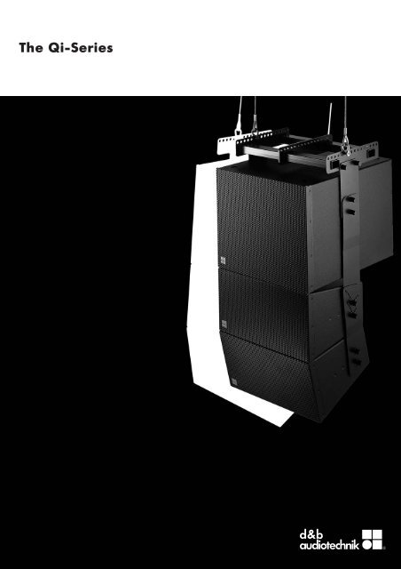
<strong>The</strong> <strong>Qi</strong>-<strong>Series</strong>
<strong>The</strong> <strong>Qi</strong>-<strong>Series</strong><br />
<strong>The</strong> d&b <strong>Qi</strong>-<strong>Series</strong> is a collection of loudspeaker systems and<br />
hardware fittings specifically targeted for fixed installation use.<br />
Based on the established d&b Q-<strong>Series</strong> product range the <strong>Qi</strong>-<strong>Series</strong><br />
loudspeakers are the perfect option for speech and music in many<br />
theatre, conference and orchestral situations where multiple open<br />
microphones are used and considerable gain before feedback is<br />
an absolute requirement. In fact the transparency, bandwidth, high<br />
power and headroom capabilities make the <strong>Qi</strong>-<strong>Series</strong> ideal for<br />
any type of amplified music.<br />
<strong>The</strong> <strong>Qi</strong>-<strong>Series</strong> includes loudspeakers and specialized accessories<br />
that can be properly colour matched to interior designs, are<br />
mechanically adapted for installation use and can provide protection<br />
in climatically hostile environments. Control of dispersion behaviour<br />
is a particular fixation at d&b, while at the same time keeping the<br />
size and weight of systems to an absolute minimum.<br />
<strong>The</strong> <strong>Qi</strong>-<strong>Series</strong> maintains the ”d&b specific” combination of natural,<br />
intelligible sound character that is clear and transparent, even at<br />
high sound pressure levels providing the engineer with an efficient,<br />
effortless tool and a neutral platform. Combining loudspeakers,<br />
electronics, accessories, remote control, documentation, data,<br />
product support and service to create complete, integrated solutions<br />
for sound reinforcement applications. Accurate performance data<br />
for industry standard simulation software allows the installation<br />
designer to create solutions that are predictable and reliable<br />
across a wide range of application settings, from the smallest to<br />
the largest venue.<br />
Aesthetics are not the only factors and constraints affecting the<br />
placement of loudspeakers in an installed environment; in certain<br />
applications it may be desirable to deploy a system with a wide<br />
horizontal dispersion pattern rotated to deliver wider vertical<br />
coverage while narrowing the horizontal profile. Conversely, space<br />
restrictions may require a loudspeaker to be mounted sideways<br />
whilst the electroacoustic needs dictate mounting the device<br />
upright. Fulfillment of these needs is achieved either by using the<br />
d&b bespoke installation hardware or by turning through 90° the<br />
specially designed rotatable horns within the loudspeaker cabinet.<br />
<strong>The</strong> d&b <strong>Qi</strong>-<strong>Series</strong> consists of the 2-way passively crossed over<br />
<strong>Qi</strong>1, <strong>Qi</strong>7 and <strong>Qi</strong>10 loudspeaker cabinets that are designed to<br />
be totally mechanically compatible, sharing the same physical size,<br />
shape, rigging and driver compliment. <strong>The</strong> highest degree of<br />
constant directivity is maintained using a large frequency overlap<br />
through the crossover range, while the recessed dipolar positioning<br />
of the two 10” low frequency drivers mechanically time aligns them<br />
with the 1.3” exit HF driver. <strong>The</strong> <strong>Qi</strong>1 HF driver is fitted with a toroidal<br />
wave shaping device, which has a 75° x 15° (h x v) dispersion<br />
pattern and the resulting curved coherent wave front allows vertical<br />
arrays of multiple cabinets to be constructed. <strong>The</strong> <strong>Qi</strong>7 and <strong>Qi</strong>10<br />
loudspeakers also use a 1.3” HF driver fitted to rotatable 75° x 40°<br />
and 110° x 40° (h x v) constant directivity horns allowing them to<br />
be configured for use both vertically or horizontally. When<br />
deployed upright, the <strong>Qi</strong>7 and <strong>Qi</strong>10 are accurate stand-alone<br />
full range loudspeakers with vertical directivity control extending<br />
approximately one octave below similarly sized biaxial loudspeakers.<br />
When deployed horizontally with the horn rotated, the horizontal<br />
dispersion control of the <strong>Qi</strong>7 is maintained down to approximately<br />
400 Hz.<br />
<strong>The</strong> <strong>Qi</strong>-SUB completes the <strong>Series</strong> sharing the same width as the<br />
other three loudspeakers and has compatible flying fittings<br />
enabling its use in columns with other <strong>Qi</strong>-<strong>Series</strong> loudspeakers. <strong>The</strong><br />
<strong>Qi</strong>-SUB is a bass-reflex design with an 18” high excursion driver.<br />
Multiples of three <strong>Qi</strong>-SUBs can be combined to produce Cardioid<br />
Subwoofer Arrays (CSA) when driven by the D6 or D12 amplifier.<br />
<strong>The</strong> D12 amplifier incorporates d&b SenseDrive technology for<br />
accurate control of driver membranes.<br />
<strong>The</strong> <strong>Qi</strong> Mounting system for the <strong>Qi</strong>-<strong>Series</strong> consists of highly<br />
versatile frames, plates and rigging devices that facilitate the<br />
deployment of visually discreet vertical arrays or individually<br />
mounted cabinets. Rigging parts can also be colour coordinated<br />
or treated for weather resistance.<br />
<strong>The</strong> d&b D6 and D12 dual channel amplfiers realize the complete<br />
system. <strong>The</strong>y provide two different power ranges, contain<br />
loudspeaker specific controller configurations for d&b loudspeakers,<br />
including the <strong>Qi</strong>-<strong>Series</strong> loudspeakers and have analog and digital<br />
signal inputs and links. <strong>The</strong>se devices are specially designed and<br />
manufactured by d&b utilizing Digital Signal Processing and include<br />
switchable functions for precisely tailoring system response for a<br />
wide variety of applications. A user definable 4-band parametric<br />
equalizer and a delay capability is provided in every amplifier<br />
channel to reduce the need for external processing devices. <strong>The</strong><br />
D12 amplifier additionally offers a 2-Way Active mode and a<br />
mixed TOP/SUB output configuration, output connector options as<br />
well as d&b SenseDrive.<br />
Both amplifiers have d&b Remote network interfaces enabling<br />
control and monitoring of a large number of system functions and<br />
extensive system integration capabilities. d&b Load monitoring and<br />
System check are also incorporated to remotely monitor loudspeaker<br />
driver status.<br />
To complete the picture, the <strong>Qi</strong>-<strong>Series</strong> maintains the d&b maxim<br />
of compatibility between systems enabling them to be easily<br />
combined with all other d&b products. Together these components<br />
create complete, integrated, flexible installation solutions from the<br />
simplest to the most complex situations.
<strong>The</strong> <strong>Qi</strong>-<strong>Series</strong><br />
<strong>Qi</strong>1 loudspeaker<br />
<strong>Qi</strong>7, <strong>Qi</strong>10 loudspeaker<br />
<strong>Qi</strong>, <strong>Qi</strong>CSA subwoofer<br />
D6 amplifier<br />
D12 amplifier
VOLTAGE SEE LABEL<br />
~ 50/60 Hz, 1000 W<br />
<strong>The</strong> D6 and D12 amplifiers<br />
D6 and D12 amplifiers<br />
<strong>The</strong> D6 and D12 are dual channel amplifiers developed and<br />
manufactured by d&b utilizing Digital Signal Processing (DSP) to<br />
incorporate loudspeaker specific configuration information and<br />
functions. <strong>The</strong>se are designed for use with d&b loudspeakers, have<br />
both digital and analog signal inputs as well as link outputs, remote<br />
control and monitoring capabilities and switch mode power supplies.<br />
<strong>The</strong> level control incorporates a digital rotary encoder enabling<br />
selection of all operating modes in conjunction with a Liquid<br />
Crystal Display (LCD).<br />
Loudspeaker specific configurations for current d&b loudspeakers<br />
and a linear mode are contained within them, the exception<br />
being that the D6 does not include 2-Way Active and B2-SUB<br />
configurations.<br />
<strong>The</strong> digital elements of the D6 and D12 are specified and<br />
constructed to achieve the best possible audio performance while<br />
maintaining a very low latency of 0.3 msec. <strong>The</strong> Digital Signal<br />
Processing is used to provide the loudspeaker specific configurations,<br />
sophisticated protection circuits modelling thermal and mechanical<br />
driver behaviour, and switch functions.<br />
User definable equalization and delay functions are incorporated<br />
in each channel of the amplifiers and can be used for applications<br />
such as front fills or under balcony delays without the need for<br />
external processors. <strong>The</strong> signal delay capability allows delay settings<br />
of up to 340 msec. (= 100 m/328 ft) to be applied independently<br />
to each channel as can the 4-band parametric equalizer, providing<br />
optional Boost/Cut or Notch filtering. A signal generator offering<br />
pink noise or sine wave program is also incorporated for test<br />
and alignment purposes. Every unit can be given a unique<br />
Device Name to simplify identification and a password protected<br />
LOCK function is also incorporated to prevent unauthorized<br />
changes.<br />
<strong>The</strong> D6 and D12 amplifiers also detect incoming Pilot signals at its<br />
input (Input monitoring) and can use Load monitoring and System<br />
check functions to determine the status of the loudspeaker impedance.<br />
d&b System check is designed to verify that the system performs<br />
within a predefined condition and can be used to report the<br />
system condition after a show.<br />
d&b Load monitoring, on the other hand, enables automatic and<br />
continuous impedance monitoring and along with Input monitoring<br />
is designed for incorporation within applications specified to the<br />
requirements stated in the International Standard IEC 60849<br />
‘Sound Systems for Emergency Purposes’. Both can determine the<br />
status of an LF or HF driver in systems with multiple elements, even<br />
if these are crossed over passively.<br />
<strong>The</strong> D6 utilizes a switch mode power supply with PFC suitable for<br />
mains supply voltages 100 V/115 V/200 V/230 V, 50 - 60 Hz whilst<br />
the D12 utilizes an autosensing switch mode power supply for<br />
mains voltages 115/230 V, 50 - 60 Hz (optional 100/200 V). Both<br />
power supplies have over voltage protection and each amplifier<br />
has a temperature and signal controlled fan to cool the internal<br />
assemblies.<br />
<strong>The</strong> 2 RU lightweight D6 is specifically designed to deliver medium<br />
power into low impedance loads between 4 and 16 ohms. <strong>The</strong><br />
3 RU D12 is specifically designed to produce high power into low<br />
impedance loads, typically those between 4 and 16 ohms. Due to<br />
differences in impedance response against frequency, the maximum<br />
number of cabinets driven by each D12 channel varies depending<br />
on the loudspeaker type.<br />
Apart from selectable output configurations for dual channel, mixed<br />
TOP/SUB and 2-Way Active mode, the D12 also provides d&b<br />
SenseDrive for use with the LF drivers in d&b active loudspeakers<br />
and subwoofers.<br />
Both amplifiers house an I/O panel containing: analog signal<br />
inputs with link outputs for each channel, an AES/EBU digital input<br />
with a link output and NL4 loudspeaker outputs. <strong>The</strong> D12 I/O<br />
panel additionally offers the options of EP5 or NL8 loudspeaker<br />
outputs. <strong>The</strong> two RJ 45 REMOTE sockets at the rear of the D6 and<br />
the D12 amplifiers integrate them into the d&b Remote network<br />
via CAN-Bus, enabling remote control and/or monitoring.<br />
A USB-B (D6) or a SUB-D9 (D12) SERVICE interface is provided<br />
to enable future firmware updates containing new loudspeaker<br />
configurations or additional functions to be loaded to the units.<br />
D6<br />
MAINS SUPPLY<br />
CH A<br />
DIGITAL AES/EBU ANALOG<br />
OUT<br />
A<br />
OUT<br />
B<br />
REMOTE<br />
SERVICE<br />
CH B<br />
D6 rear view<br />
D12 rear view
<strong>The</strong> D6 and D12 amplifier data<br />
D6 Display<br />
ISP, GR, OVL A/B................................................................LED indicators<br />
Liquid Crystal Display (LCD).................Graphic display/120 x 32 Pixel<br />
D6 Controls<br />
POWER, MUTE /LEVEL...................................Switches/rotary encoder<br />
Function switches.........................................Loudspeaker specific circuits<br />
4-band equalizer....................................................Optional PEQ/Notch<br />
Delay setting...............................0.3 - 340 msec. with 0.1 msec. detents<br />
Configurations.................Current d&b loudspeakers and linear mode<br />
.............................................................except 2-Way Active and B2-SUB<br />
Frequency generator...........................................Pink noise or Sine wave<br />
D6 Connectors<br />
INPUT/LINK ANALOG A/B............................3 pin XLR female/male 1<br />
INPUT/LINK DIGITAL AES/EBU.....................3 pin XLR female/male 1<br />
Sampling rate.....................................................................48 kHz /96 kHz<br />
OUT CHANNEL A/B...........................................................................NL4<br />
REMOTE...........................................................................2 x RJ 45 parallel<br />
SERVICE......................................................................................USB Type B<br />
D6 Protection circuits<br />
Mains inrush current limiter.......................................1.5 A RMS at 230 V<br />
Loudspeaker switch on delay.............................................Approx. 2 sec.<br />
Overvoltage protection....................................................Up to 400 VAC<br />
D6 Data (linear setting with subsonic filter)<br />
Rated output power (THD+N < 0.1%)......................................................<br />
..................................2 x 350 W into 8 ohms, both channels are driven<br />
..................................2 x 600 W into 4 ohms, both channels are driven<br />
S/N ratio (unweighted, RMS).....................................................>110 dBr<br />
D6 Digital Signal Processing<br />
Sampling rate.......................................96 kHz/27 Bit ADC/24 Bit DAC<br />
Basic delay/latency analog input..............................................0.3 msec.<br />
D6 Power supply<br />
Switch mode power supply for....................................................................<br />
................................................................100/115 /200 /230V, 50 - 60 Hz<br />
Mains connector......................................................................PowerCon ® 2<br />
D6 Remote network<br />
Remote network............................................................................CAN-Bus<br />
D6 Dimensions, weight<br />
Height x width x depth................................2 RU x 19” x 353 mm/13.9”<br />
Weight........................................................................................8 kg/17.6 lb<br />
D12 Display<br />
ISP, GR, OVL A/B................................................................LED indicators<br />
Liquid Crystal Display (LCD).................Graphic display/120 x 32 Pixel<br />
D12 Controls<br />
POWER, MUTE /LEVEL...................................Switches/rotary encoder<br />
Function switches.........................................Loudspeaker specific circuits<br />
4-band equalizer....................................................Optional PEQ/Notch<br />
Delay setting...............................0.3 - 340 msec. with 0.1 msec. detents<br />
Configurations.................Current d&b loudspeakers and linear mode<br />
Frequency generator...........................................Pink noise or Sine wave<br />
D12 Connectors<br />
INPUT/LINK ANALOG A /B........................3 pin XLR female/male 1<br />
INPUT/LINK DIGITAL AES/EBU..................3 pin XLR female/male 1<br />
Sampling rate.....................................................................48 kHz /96 kHz<br />
OUT CHANNEL A/B.....................................Optional EP5/NL4/NL8<br />
REMOTE...........................................................................2 x RJ 45 parallel<br />
SERVICE..............................................................................SUB-D9 female<br />
D12 Protection circuits<br />
Mains inrush current limiter..........................................5 A RMS at 230 V<br />
Loudspeaker switch on delay.............................................Approx. 2 sec.<br />
Overvoltage protection....................................................Up to 400 VAC<br />
D12 Data (linear setting with subsonic filter)<br />
Rated output power (THD+N < 0.1%)......................................................<br />
..................................2 x 750 W into 8 ohms, both channels are driven<br />
................................2 x 1200 W into 4 ohms, both channels are driven<br />
S/N ratio (unweighted, RMS).....................................................>110 dBr<br />
D12 Digital Signal Processing<br />
Sampling rate.......................................96 kHz /27 Bit ADC/24 Bit DAC<br />
Basic delay/latency analog input..............................................0.3 msec.<br />
D12 Power supply<br />
Autosensing switch mode power supply for..............................................<br />
..................................................................................115 /230 V, 50 - 60 Hz<br />
.................................................................optional 100/200 V, 50 - 60 Hz<br />
Mains connector......................................................................PowerCon ®2<br />
D12 Remote network<br />
Remote network............................................................................CAN-Bus<br />
D12 Dimensions, weight<br />
Height x width x depth................................3 RU x 19” x 353 mm/13.9”<br />
Weight........................................................................................13 kg/29 lb<br />
1<br />
XLR pin assignment analog, inputs and links: 1 = GND, 2 = pos. signal, 3 = neg. signal<br />
XLR pin assignment digital, input and link: 1 = GND, 2 = signal, 3 = signal<br />
2<br />
PowerCon ® is a registered trademark of the Neutrik AG, Liechtenstein
<strong>The</strong> d&b Remote network<br />
d&b Remote network<br />
<strong>The</strong> d&b Remote network enables central control and monitoring<br />
of a complete d&b loudspeaker system from anywhere in the<br />
network, be it from a PC in the control room, at the mix position,<br />
or on a wireless tablet PC in the auditorium.<br />
This central access to all functions, controls and detailed system<br />
information unlocks the full potential of the d&b system approach.<br />
It effectively speeds up the execution of various tasks during<br />
configuration and offers significant advantages during operation.<br />
Extensive monitoring and diagnostics enables detailed examination<br />
of the system performance. Control can be undertaken on individual<br />
loudspeakers, on multiple groups of loudspeakers or formed into<br />
groups that address the complete system.<br />
<strong>The</strong> flexibility and scalability of this approach, coupled with the<br />
inclusion of several types of interfaces, allow the d&b Remote network<br />
to be deployed to address the differing control and monitoring<br />
requirements in a broad variety of mobile and installed applications,<br />
regardless of their size.<br />
In mobile applications, system engineers may use the remote<br />
network to verify and tune the system. System check and device<br />
diagnostics enable detailed monitoring as and when required,<br />
before, during, or after a show.<br />
In installation projects system integrators can configure the remote<br />
network to offer access to different levels of control tailored to the<br />
operational demands. For example, simplified functionality for<br />
daily use and more complex functionality when multiple applications<br />
are required within one installation. Input and Load monitoring<br />
coupled with automatic error messages allow installation operators<br />
to ensure the optimum performance at all times.<br />
Terminating<br />
connector<br />
Daisy chain<br />
d&b Remote network<br />
Z6118 R60 USB to CAN interface<br />
D6<br />
D6<br />
D6<br />
CAN-Bus<br />
CAN-Bus<br />
interface<br />
Computer running<br />
R1 or R10<br />
d&b Remote interfaces<br />
Every d&b amplifier is fitted with a Remote interface for the<br />
Controller Area Network (CAN) Bus. Each D6 and D12 has two<br />
REMOTE connectors (RJ 45) to enable the CAN-Bus signal to<br />
be daisy chained through them. A simple d&b Remote network<br />
application consists of a computer running R1 Remote control<br />
software, an R60 USB to CAN interface, CAT 5 shielded twisted<br />
pair cable with shielded RJ 45 connectors and d&b D6 or D12<br />
amplifiers.<br />
Up to five R60 USB to CAN interfaces can be operated with one<br />
computer running R1, while a maximum of 504 amplifiers can be<br />
incorporated into one application. <strong>The</strong> maximum bus cable length<br />
of a d&b Remote network is 600 metres, see the adjoining table<br />
for cable length examples. <strong>The</strong> R70 Ethernet to CAN interface can<br />
be used for applications over longer distances, in conjunction with<br />
a fibre optic network for example.<br />
For further information about CAN-Bus cabling requirements and<br />
interfaces please refer to the d&b TI 312 d&b Remote network,<br />
which is available for download at www.dbaudio.com.<br />
Z6124 R70 Ethernet to CAN interface<br />
Cable cross<br />
section<br />
0,25 mm 2 (24 AWG)<br />
0,75 mm 2 (18 AWG)<br />
Examples of bus cable length<br />
Maximum bus cable length<br />
with numbers of amplifiers<br />
32 100<br />
180 m (600 ft) 140 m (460 ft)<br />
500 m (1650 ft) 330 m (1100 ft)
<strong>The</strong> d&b Remote software<br />
R1 main page, groups and master controls<br />
R1 device page, individual devices, details view and<br />
group controls<br />
R1 Remote control software<br />
R1 Remote control software is a graphical drag and drop user<br />
interface enabling the construction of a screen based virtual control<br />
surface for d&b systems, using the d&b Remote network.<br />
All major features, functions and controls available on the front<br />
panel of the D6 and D12 amplifiers may be remotely controlled<br />
and/or monitored using R1. <strong>The</strong> architecture of R1 allows control<br />
of each channel of the amplifier as a single entity and enables the<br />
creation of groups of loudspeakers in as little, or as much detail as<br />
required by the user. When grouped together, a button or fader<br />
can control the overall system level, zone level, equalization and<br />
delay, power ON /OFF, MUTE and loudspeaker function switches<br />
such as CUT/HFA/HFC or CPL.<br />
R1 has extensive facilities for storing and recalling system settings<br />
allowing these to be repeated, as and when required. It is easy<br />
to adjust R1 project files for use with a different set of equipment<br />
at another location. Password protection is available to restrict<br />
access.<br />
R1 runs on PCs operating Microsoft Windows 2000 SP4/XP<br />
SP2/Vista 1 .A virtual machine enables R1 to run on the newer Intel 2<br />
Mac 3 in parallel to the Mac OS X 3 , using the Windows driver for<br />
R60 USB to CAN interface.<br />
For older, Power PC based Mac computers, Windows emulation<br />
needs to be used, together with the R60 driver for Mac/PPC. For<br />
R70 Ethernet to CAN, no driver is needed.<br />
All the latest available drivers, R1 example files that can be used<br />
as templates and the TI 390 describing the effective use of R1 are<br />
available for download at www.dbaudio.com.<br />
R10 Service software<br />
R10 Service software enables the simultaneous amplifier firmware<br />
update of up to 63 amplifiers from a central location. Using R10,<br />
AmpPresets can be adjusted to the application requirements.<br />
Integration with media control<br />
For integration of d&b audiotechnik loudspeaker systems into media<br />
control applications, the R70 Ethernet to CAN interface is used. AMX<br />
and Crestron modules (drivers) are available at www.dbaudio.com.<br />
EN 60849 voice alarm applications<br />
For remote control of voice alarm applications Programmable<br />
Logic Controllers (PLCs) can be integrated into the d&b Remote<br />
network.<br />
R10 Service software<br />
1<br />
Microsoft and Windows 2000/XP/Vista are either registered trademarks or trademarks<br />
of Microsoft Corporation in the United States and/or other countries<br />
2<br />
Intel is a trademark of the Intel Corporation in the United States and other countries<br />
3<br />
Mac and Mac OS X are trademarks of Apple Inc., registered in the United States and<br />
other countries
<strong>The</strong> <strong>Qi</strong>1 loudspeaker<br />
<strong>Qi</strong>1 loudspeaker<br />
<strong>The</strong> <strong>Qi</strong>1 is the installation version of the Q1 line array loudspeaker.<br />
It is acoustically compatible with the standard road version differing<br />
only in cabinet construction and mounting hardware.<br />
<strong>The</strong> <strong>Qi</strong>1 cabinet is a passive 2-way design that houses 2 x 10”<br />
LF drivers and a 1.3” HF compression driver with a toroidal wave<br />
shaping device to achieve a 75° x 15° (h x v) dispersion<br />
characteristic. <strong>The</strong> two 10” neodymium LF drivers are positioned<br />
in a dipolar arrangement providing an exceptional dispersion<br />
control even at lower frequencies with the 75° nominal dispersion<br />
angle being maintained down to 400 Hz.<br />
<strong>The</strong> <strong>Qi</strong>-SUB subwoofer extends the system frequency response<br />
to below 40 Hz, for further extension of bandwidth and headroom<br />
ground stacked B2 subwoofers can be used (driven in INFRA<br />
mode).<br />
<strong>The</strong> <strong>Qi</strong>1 cabinet is constructed from marine plywood and has an<br />
impact resistant paint finish. <strong>The</strong> front of the loudspeaker cabinet is<br />
covered with a replaceable acoustically transparent foam that is<br />
then protected by a rigid metal grill. Four M10 threaded inserts on<br />
each side panel of the cabinet enclosure are provided for attaching<br />
installation hardware. <strong>The</strong> cabinet rear panel is fitted with two NL4<br />
connectors wired in parallel. <strong>The</strong> weather resistant (WR) version<br />
comes supplied with a fixed cable.<br />
<strong>Qi</strong>1 horizontal dispersion characteristics 2<br />
<strong>Qi</strong>1 vertical dispersion characteristics 2<br />
System data<br />
Frequency response (–5 dB standard).............................60 Hz - 17 kHz<br />
Max. sound pressure (1 m, free field) 1 .......................................................<br />
with D6................................................................................................135 dB<br />
with D12..............................................................................................139 dB<br />
Input level (100 dB SPL /1 m).........................................................–18 dBu<br />
Polarity to amplifier INPUT (XLR pin 2: +/3: –)................LF: +/HF: –<br />
580 [22.83"]<br />
308 [12.13"]<br />
204.5 [8.05"]<br />
154 [6.06"]<br />
60 [2.36"]<br />
310 [12.20"]<br />
15°<br />
Loudspeaker data<br />
Nominal impedance.........................................................................8 ohms<br />
Power handling capacity (RMS /peak 10 ms)...................400/1600 W<br />
Nominal dispersion angle (h x v)................................................75° x 15°<br />
Components...............................2 x 10” driver/1.3” compression driver<br />
............................................................................Passive crossover network<br />
Connections......................................................................2 x NL4 (1+/1–)<br />
Connection option....................................................................Fixed cable<br />
Weight.......................................................................................21 kg (46 lb)<br />
410 [16.14"]<br />
<strong>Qi</strong>1 cabinet dimensions in mm (inch)<br />
1<br />
Broadband measurement, pink noise, crest factor 4, peak measurement, linear<br />
weighting<br />
2<br />
Dispersion angle vs frequency plotted using lines of equal sound pressure (isobars)<br />
at –6 dB and –12 dB
<strong>The</strong> D6 and D12 configurations<br />
<strong>Qi</strong>1 frequency response, standard and CUT modes<br />
(single cabinet)<br />
Frequency response correction of HFC circuit<br />
<strong>Qi</strong>1 with D6 and D12<br />
Selecting Q1 configuration in the D6 and D12 dual channel<br />
amplifiers enables up to two <strong>Qi</strong>1 loudspeakers to be driven by the<br />
respective channel. In applications with low continuous levels and<br />
low ambient temperatures up to three loudspeakers per D12<br />
channel may be connected.<br />
A line configuration is available in D6 and D12 for groups of four<br />
or more <strong>Qi</strong>1 loudspeakers, which are coupled to a straight long<br />
throw array section. Compared to the standard configuration, the<br />
mid/-high range is reduced to compensate for the extended near<br />
field.<br />
For acoustic adjustment the functions CUT, HFC and CPL can be<br />
selected.<br />
Set to CUT, the <strong>Qi</strong>1 low frequency level is reduced. <strong>The</strong> <strong>Qi</strong>1 is now<br />
configured for use with active d&b subwoofers.<br />
Selecting the HFC (High Frequency Compensation) circuit<br />
compensates for loss of high frequency energy due to absorption in<br />
air when loudspeakers are used to cover far field listening positions.<br />
<strong>The</strong> HFC circuit should be used selectively, only for those cabinets<br />
covering distances larger than 50 m (160 ft). This enables the correct<br />
sound balance between close and remote audience areas, whilst all<br />
amplifiers driving the array can be fed with the same signal.<br />
<strong>The</strong> CPL (Coupling) circuit compensates for coupling effects between<br />
the cabinets; these effects increase as the length of the line array<br />
is extended. CPL begins gradually at 1 kHz, with the maximum<br />
attenuation below 400 Hz, providing a balanced frequency<br />
response when <strong>Qi</strong>1 cabinets are used in arrays of four or more.<br />
<strong>The</strong> function of the CPL circuit in these amplifiers is shown in the<br />
diagram opposite and can be set in dB attenuation values between<br />
–9 and 0, or a positive CPL value which creates an adjustable low<br />
frequency boost around 65 Hz (0 to +5 dB).<br />
Frequency response correction of CPL circuit
<strong>The</strong> <strong>Qi</strong>7 loudspeaker<br />
<strong>Qi</strong>7 loudspeaker<br />
<strong>The</strong> <strong>Qi</strong>7 is the installation version of the Q7 loudspeaker. It is<br />
acoustically compatible with the standard road version differing<br />
only in cabinet construction and mounting hardware.<br />
<strong>The</strong> <strong>Qi</strong>7 is a 75° x 40° passive 2-way loudspeaker housing 2 x 10”<br />
LF drivers and a 1.3” HF compression driver with a rotatable<br />
constant directivity horn and a passive crossover network. <strong>The</strong> two<br />
10” neodymium LF drivers are positioned in a dipolar arrangement<br />
providing exceptional vertical dispersion control with the 40° nominal<br />
dispersion angle being maintained down to 400 Hz. <strong>The</strong> precisely<br />
controlled 75° horizontal dispersion performance provides the<br />
ideal pattern for many medium throw requirements. <strong>The</strong> <strong>Qi</strong>7 horn<br />
can be rotated by 90°. <strong>The</strong> horizontal <strong>Qi</strong>7 setup with rotated horn<br />
is used to mount the loudspeaker horizontally where space is<br />
limited, or the maximum horizontal pattern control is needed. <strong>The</strong><br />
rotated setup is also used when <strong>Qi</strong>7s are added horizontally to<br />
the bottom of <strong>Qi</strong>1 arrays.<br />
<strong>The</strong> <strong>Qi</strong>7 cabinet is constructed from marine plywood and has an<br />
impact resistant paint finish. <strong>The</strong> front of the loudspeaker cabinet is<br />
covered with a replaceable acoustically transparent foam that is<br />
then protected by a rigid metal grill. Four M10 threaded inserts on<br />
each side panel of the cabinet enclosure are provided for attaching<br />
installation hardware. <strong>The</strong> cabinet rear panel is fitted with two NL4<br />
connectors wired in parallel. <strong>The</strong> weather resistant (WR) version<br />
comes supplied with a fixed cable.<br />
<strong>Qi</strong>7 horizontal dispersion characteristics 2<br />
<strong>Qi</strong>7 vertical dispersion characteristics 2<br />
System data<br />
Frequency response (–5 dB standard).............................60 Hz - 17 kHz<br />
Max. sound pressure (1 m, free field) 1 .......................................................<br />
with D6................................................................................................134 dB<br />
with D12..............................................................................................138 dB<br />
Input level (100 dB SPL/1 m).........................................................–17 dBu<br />
Polarity to amplifier INPUT (XLR pin 2: +/3: –)................LF: +/HF: –<br />
<strong>Qi</strong>7 horizontal dispersion characteristics/<br />
rotated horn 2<br />
Loudspeaker data<br />
Nominal impedance.........................................................................8 ohms<br />
Power handling capacity (RMS /peak 10 ms)...................400/1600 W<br />
Nominal dispersion angle (h x v)................................................75° x 40°<br />
Components...............................2 x 10” driver/1.3” compression driver<br />
............................................................................Passive crossover network<br />
Connections......................................................................2 x NL4 (1+/1–)<br />
Connection option....................................................................Fixed cable<br />
Weight.......................................................................................21 kg (46 lb)<br />
<strong>Qi</strong>7 vertical dispersion characteristics/<br />
rotated horn 2<br />
1<br />
Broadband measurement, pink noise, crest factor 4, peak measurement, linear<br />
weighting<br />
2<br />
Dispersion angle vs frequency plotted using lines of equal sound pressure (isobars)<br />
at –6 dB and –12 dB
<strong>The</strong> D6 and D12 configurations<br />
<strong>Qi</strong>7 frequency response, standard and CUT modes<br />
10<br />
5<br />
0<br />
-5<br />
-10<br />
-15<br />
-20<br />
-25<br />
-30<br />
20 100 1k 10k 20k<br />
Frequency response correction of HFA circuit<br />
Frequency response correction of CPL circuit<br />
<strong>Qi</strong>7 with D6 and D12<br />
Selecting Q7 configuration in the D6 and D12 dual channel<br />
amplifiers enables up to two <strong>Qi</strong>7 loudspeakers to be driven by<br />
the respective channel. In applications with low continuous levels<br />
and low ambient temperatures up to three loudspeakers per D12<br />
channel may be connected.<br />
For acoustic adjustment the functions CUT, HFA and CPL can be<br />
selected.<br />
Set to CUT, the <strong>Qi</strong>7 low frequency level is reduced. <strong>The</strong> <strong>Qi</strong>7 is<br />
now configured for use with d&b active subwoofers.<br />
In HFA mode (High Frequency Attenuation), the HF response of<br />
the <strong>Qi</strong>7 system is rolled off. <strong>The</strong> HFA provides a natural, balanced<br />
frequency response when a unit is placed close to listeners in near<br />
field or delay use. High Frequency Attenuation begins gradually<br />
at 1 kHz, dropping by approximately 3 dB at 10 kHz. This roll off<br />
mimics the decline in frequency response experienced when<br />
listening to a system from a distance in a typically reverberant<br />
room or auditorium.<br />
<strong>The</strong> CPL (Coupling) circuit compensates for coupling effects between<br />
the cabinets when building closely coupled arrays. CPL begins<br />
gradually at 1 kHz, with maximum attenuation below 400 Hz,<br />
providing a balanced frequency response when <strong>Qi</strong>7 cabinets are<br />
used in arrays of two or more. <strong>The</strong> function of the CPL circuit in<br />
these amplifiers is shown in the diagram opposite and can be set<br />
in dB attenuation values between –9 and 0, or a positive CPL<br />
value which creates an adjustable low frequency boost around<br />
65 Hz (0 to +5 dB).<br />
154 [6.06"]<br />
60 [2.36"]<br />
580 [22.83"]<br />
308 [12.13"]<br />
410 [16.14"]<br />
204.5 [8.05"]<br />
310 [12.2"]<br />
15°<br />
<strong>Qi</strong>7 cabinet dimensions in mm (inch)
<strong>The</strong> <strong>Qi</strong>10 loudspeaker<br />
<strong>Qi</strong>10 loudspeaker<br />
<strong>The</strong> <strong>Qi</strong>10 is the installation version of the Q10 loudspeaker. It is<br />
acoustically compatible with the standard road version differing<br />
only in cabinet construction and mounting hardware.<br />
<strong>The</strong> <strong>Qi</strong>10 is a 110° x 40° passive 2-way loudspeaker housing<br />
2 x 10” LF drivers and a 1.3” HF compression driver with a rotatable<br />
constant directivity horn and a passive crossover network. <strong>The</strong> two<br />
10” neodymium LF drivers are positioned in a dipolar arrangement<br />
providing exceptional vertical dispersion control with the 40° nominal<br />
dispersion angle being maintained down to 400 Hz.<br />
<strong>The</strong> <strong>Qi</strong>10 is a stand-alone full range loudspeaker system when<br />
used in the upright configuration and has a very accurate 110°<br />
horizontal constant directivity behaviour that is maintained down<br />
to approximately 800 Hz. <strong>The</strong> <strong>Qi</strong>10’s wide constant directivity<br />
performance provides remarkable transparency when used in close<br />
proximity to listeners. It is also ideally suited to ambient and /or<br />
distributed sound reinforcement tasks where orientation within the<br />
sound field is critical. <strong>The</strong> performance differs considerably when the<br />
cabinet is deployed horizontally with the horn rotated by 90°. In<br />
this configuration the horizontal dispersion pattern is much narrower<br />
in the 500 Hz - 1 kHz region hence the use as a downfill in <strong>Qi</strong>1<br />
arrays for example has limitations.<br />
<strong>The</strong> <strong>Qi</strong>10 cabinet is constructed from marine plywood and has an<br />
impact resistant paint finish. <strong>The</strong> front of the loudspeaker cabinet is<br />
covered with a replaceable acoustically transparent foam that is<br />
then protected by a rigid metal grill. Four M10 threaded inserts on<br />
each side panel of the cabinet enclosure are provided for attaching<br />
installation hardware. <strong>The</strong> cabinet rear panel is fitted with two NL4<br />
connectors wired in parallel. <strong>The</strong> weather resistant (WR) version<br />
comes supplied with a fixed cable.<br />
<strong>Qi</strong>10 horizontal dispersion characteristics 2<br />
<strong>Qi</strong>10 vertical dispersion characteristics 2<br />
System data<br />
Frequency response (–5 dB standard) ............................60 Hz - 17 kHz<br />
Max. sound pressure (1 m, free field) 1 .......................................................<br />
with D6................................................................................................133 dB<br />
with D12..............................................................................................137 dB<br />
Input level (100 dB SPL /1 m).........................................................–17 dBu<br />
Polarity to controller INPUT (XLR pin 2: +/3: –).............LF: + / HF: –<br />
<strong>Qi</strong>10 horizontal dispersion characteristics/<br />
rotated horn 2<br />
Loudspeaker data<br />
Nominal impedance.........................................................................8 ohms<br />
Power handling capacity (RMS /peak 10 ms)...................400/1600 W<br />
Nominal dispersion angle (h x v)..............................................110° x 40°<br />
Components...............................2 x 10” driver/1.3” compression driver<br />
............................................................................Passive crossover network<br />
Connections......................................................................2 x NL4 (1+/1–)<br />
Connection option....................................................................Fixed cable<br />
Weight.......................................................................................21 kg (46 lb)<br />
<strong>Qi</strong>10 vertical dispersion characteristics/<br />
rotated horn 2<br />
1<br />
Broadband measurement, pink noise, crest factor 4, peak measurement, linear<br />
weighting<br />
2<br />
Dispersion angle vs frequency plotted using lines of equal sound pressure (isobars)<br />
at –6 dB and –12 dB
<strong>The</strong> D6 and D12 configurations<br />
<strong>Qi</strong>10 frequency response, standard and CUT modes<br />
10<br />
5<br />
0<br />
-5<br />
-10<br />
-15<br />
-20<br />
-25<br />
-30<br />
20 100 1k 10k 20k<br />
Frequency response correction of HFA circuit<br />
<strong>Qi</strong>10 with D6 and D12<br />
Selecting Q10 configuration in the D6 and D12 dual channel<br />
amplifiers enables up to two <strong>Qi</strong>10 loudspeakers to be driven by<br />
the respective channel. In applications with low continuous levels<br />
and low ambient temperatures up to three loudspeakers per D12<br />
channel may be connected.<br />
For acoustic adjustment the functions CUT, HFA and CPL can be<br />
selected.<br />
Set to CUT, the <strong>Qi</strong>10 low frequency level is reduced. <strong>The</strong> <strong>Qi</strong>10 is<br />
now configured for use with d&b active subwoofers.<br />
In HFA mode (High Frequency Attenuation), the HF response of<br />
the <strong>Qi</strong>10 system is rolled off. <strong>The</strong> HFA provides a natural, balanced<br />
frequency response when a unit is placed close to listeners in near<br />
field or delay use. High Frequency Attenuation begins gradually<br />
at 1 kHz, dropping by approximately 3 dB at 10 kHz. This roll off<br />
mimics the decline in frequency response experienced when<br />
listening to a system from a distance in a typically reverberant<br />
room or auditorium.<br />
<strong>The</strong> CPL (Coupling) circuit compensates for coupling effects between<br />
the cabinets when building closely coupled arrays. CPL begins<br />
gradually at 1 kHz, with maximum attenuation below 400 Hz,<br />
providing a balanced frequency response when <strong>Qi</strong>10 cabinets are<br />
used in arrays of two or more. <strong>The</strong> function of the CPL circuit in<br />
these amplifiers is shown in the diagram opposite and can be set<br />
in dB attenuation values between –9 and 0, or a positive CPL<br />
value which creates an adjustable low frequency boost around<br />
65 Hz (0 to +5 dB).<br />
Frequency response correction of CPL circuit<br />
154 [6.06"]<br />
60 [2.36"]<br />
580 [22.83"]<br />
308 [12.13"]<br />
204.5 [8.05"]<br />
410 [16.14"]<br />
310 [12.2"]<br />
15°<br />
<strong>Qi</strong>10 cabinet dimensions in mm (inch)
<strong>The</strong> <strong>Qi</strong> subwoofer<br />
<strong>Qi</strong> subwoofer<br />
<strong>The</strong> <strong>Qi</strong>-SUB is the installation version of the Q-SUB and can<br />
be used to supplement <strong>Qi</strong>1, <strong>Qi</strong>7 and <strong>Qi</strong>10 cabinets in various<br />
combinations, either flown or ground stacked. It is acoustically<br />
compatible with the standard road version differing only in cabinet<br />
construction and mounting hardware. <strong>The</strong> <strong>Qi</strong> subwoofer cabinet<br />
is an actively driven bass-reflex design housing a long excursion<br />
18” driver.<br />
<strong>The</strong> <strong>Qi</strong>-SUB cabinet is constructed from marine plywood and has<br />
an impact resistant paint finish. <strong>The</strong> front of the loudspeaker cabinet<br />
is covered with a replaceable acoustically transparent foam that is<br />
then protected by a rigid metal grill. Four M10 threaded inserts on<br />
each side panel of the cabinet enclosure are provided for attaching<br />
installation hardware. Four rubber pads placed into their recessed<br />
positions prevent movement of the cabinets when two or more<br />
<strong>Qi</strong>-SUBs are stacked. <strong>The</strong> cabinet rear panel is fitted with two NL4<br />
connectors wired in parallel. <strong>The</strong> weather resistant (WR) version<br />
comes supplied with a fixed cable.<br />
580 [22.83"]<br />
669 [26.32"]<br />
488 [19.21"]<br />
<strong>Qi</strong>-SUB cabinet dimensions in mm (inch)<br />
377 [14.84"]<br />
310 [12.20"]<br />
60 [2.36"]<br />
124 [4.88"]<br />
System data<br />
Frequency response (–5 dB standard)............................40 Hz - 130 Hz<br />
Max. sound pressure (1 m, free field) 1 .......................................................<br />
with D6................................................................................................129 dB<br />
with D12..............................................................................................133 dB<br />
Input level (100 dB SPL/1 m).........................................................–13 dBu<br />
Polarity to amplifier INPUT (XLR pin 2: +/3: –)..............................LF: +<br />
Loudspeaker data<br />
Nominal impedance.........................................................................8 ohms<br />
Power handling capacity (RMS /peak 10 ms)...................400/1600 W<br />
Components..................................................................................18” driver<br />
Connections.....................................................................2 x NL4 (2+/2–)<br />
Connection option....................................................................Fixed cable<br />
Weight.......................................................................................37 kg (81 lb)<br />
1<br />
Broadband measurement, pink noise, crest factor 4, peak measurement, linear<br />
weighting<br />
2<br />
Dispersion angle vs frequency plotted using lines of equal sound pressure (isobars)<br />
at –6 dB and –12 dB
<strong>The</strong> D6 and D12 configurations<br />
<strong>Qi</strong>-SUB frequency response, standard and 100 Hz modes<br />
<strong>Qi</strong>-SUB with D6 and D12<br />
Selecting Q-SUB configuration in the D6 and D12 dual channel<br />
amplfiers enables up to two <strong>Qi</strong>-SUB loudspeakers to be driven<br />
by the respective channel. In applications with low continuous<br />
levels and low ambient temperatures up to three loudspeakers per<br />
D12 channel may be connected.<br />
For acoustic adjustment the functions 100 Hz can be selected.<br />
If the 100 Hz mode is selected, the upper operating frequency of<br />
the system is reduced from 130 Hz to 100 Hz.<br />
<strong>The</strong> D12 incorporates d&b SenseDrive for accurate control of driver<br />
membranes in d&b subwoofers, resulting in an extremely precise<br />
bass performance, even at high levels. SenseDrive is only available<br />
using a D12 fitted with EP5 connectors and appropriate 3-wire<br />
cabling. For further information please refer to the d&b TI 340<br />
SenseDrive, which is available for download at www.dbaudio.com.
<strong>The</strong> <strong>Qi</strong>CSA subwoofer<br />
<strong>Qi</strong>CSA subwoofer<br />
<strong>The</strong> <strong>Qi</strong>CSA-SUB is a specifically designed version of the <strong>Qi</strong>-SUB<br />
for use as the rear facing element in Cardioid Subwoofer Arrays<br />
(CSA) only. It is acoustically compatible with the standard road<br />
version differing only in cabinet construction and mounting<br />
hardware. <strong>The</strong> <strong>Qi</strong>CSA subwoofer cabinet is an actively driven<br />
bass-reflex design housing a long excursion 18" driver.<br />
<strong>The</strong> <strong>Qi</strong>CSA-SUB cabinet is constructed from marine plywood and<br />
has an impact resistant paint finish. <strong>The</strong> loudspeaker cabinet has<br />
replaceable acoustically transparent foams fitted to both the front<br />
and rear sides of the cabinet, which are then protected by rigid<br />
metal grills. Four M10 threaded inserts on each side panel of the<br />
cabinet enclosure are provided for attaching installation hardware.<br />
Four rubber pads placed into their recessed positions prevent<br />
movement of the cabinets when two or more <strong>Qi</strong> and <strong>Qi</strong>CSA-SUBs<br />
are stacked. <strong>The</strong> grill facing backwards is fitted with a single NL4<br />
connector at the bottom left hand side. <strong>The</strong> weather resistant (WR)<br />
version is supplied with a fixed cable.<br />
580 [22.83"]<br />
488 [19.21"]<br />
684 [26.93"]<br />
<strong>Qi</strong>CSA-SUB cabinet dimensions in mm (inch)<br />
377 [14.84"]<br />
310 [12.20"]<br />
60 [2.36"]<br />
124 [4.88"]<br />
System data<br />
Frequency response (–5 dB standard)............................40 Hz - 130 Hz<br />
Max. sound pressure (1 m, free field) 1 ........................................................<br />
with D6................................................................................................129 dB<br />
with D12..............................................................................................133 dB<br />
Input level (100 dB SPL/1 m).........................................................–13 dBu<br />
Polarity to amplifier INPUT (XLR pin 2: +/3: –)..............................LF: +<br />
Loudspeaker data<br />
Nominal impedance.........................................................................8 ohms<br />
Power handling capacity (RMS /peak 10 ms)...................400 /1600 W<br />
Components..................................................................................18” driver<br />
Connections.....................................................................1 x NL4 (2+/2–)<br />
Connection option....................................................................Fixed cable<br />
Weight......................................................................................40 kg (88 lb)<br />
1<br />
Broadband measurement, pink noise, crest factor 4, peak measurement, linear<br />
weighting
<strong>The</strong> D6 and D12 configurations<br />
<strong>Qi</strong>CSA-SUB frequency response, standard and 100 Hz modes<br />
rear<br />
front<br />
CSA configuration example<br />
<strong>Qi</strong>CSA-SUB with D6 and D12<br />
Selecting the Q-SUB configuration along with the CSA mode in<br />
the D6 and D12 dual channel amplifiers enables up to two<br />
<strong>Qi</strong>CSA-SUBs to be driven by the respective channel. In applications<br />
with low continuous levels and low ambient temperatures up to<br />
three loudspeakers per D12 channel may be connected.<br />
For acoustic adjustment the 100 Hz function can be selected.<br />
If the 100 Hz mode is selected, the upper operating frequency of<br />
the system is reduced from 130 Hz to 100 Hz.<br />
CSA (Cardioid Subwoofer Array) mode enables the combination<br />
of three or multiples of three subwoofer cabinets into an array<br />
that produces exceptional low frequency directivity control. <strong>The</strong><br />
centre cabinet in a column is physically pointed to the rear, as<br />
shown in the drawing opposite and the CSA mode selected on the<br />
channel that powers this cabinet. <strong>The</strong> forward facing cabinets are<br />
driven with a D6 or D12 channel set in the standard mode. <strong>The</strong><br />
resulting cardioid behaviour of the array will significantly reduce<br />
the energy radiated to the rear. For further information please<br />
refer to the d&b TI 330 Cardioid Subwoofer Array, which is available<br />
for download at www.dbaudio.com.<br />
<strong>The</strong> D12 incorporates d&b SenseDrive for accurate control of driver<br />
membranes in d&b subwoofers, resulting in an extremely precise<br />
bass performance, even at high levels. SenseDrive is only available<br />
using a D12 fitted with EP5 connectors and appropriate 3-wire<br />
cabling. For further information please refer to the d&b TI 340<br />
SenseDrive, which is available for download at www.dbaudio.com.<br />
CSA polar pattern
<strong>The</strong> <strong>Qi</strong> Mounting system<br />
<strong>Qi</strong> Mounting system<br />
<strong>The</strong> <strong>Qi</strong>-<strong>Series</strong> cabinets are fitted with threaded inserts on each<br />
side panel of the cabinet enclosure for attaching a variety of<br />
installation hardware.<br />
This mounting hardware enables <strong>Qi</strong>1 cabinets to be built into<br />
vertical arrays, <strong>Qi</strong> subwoofers to be inserted at any position and<br />
the deployment of a horizontally mounted <strong>Qi</strong>7 for nearfill use.<br />
Z5145<br />
Ci/<strong>Qi</strong> Mounting frame<br />
<strong>Qi</strong> Mounting adapters are used to attach the first <strong>Qi</strong> cabinet to<br />
the Ci/<strong>Qi</strong> Mounting frame. Additional cabinets are mounted using<br />
the <strong>Qi</strong> Mounting plates. <strong>The</strong> Ci/<strong>Qi</strong> Mounting frame can be used<br />
with the <strong>Qi</strong>-<strong>Series</strong> loudspeakers enabling an entire array to be<br />
suspended either at the centre plate or left and right using the<br />
outer plates. <strong>The</strong> Ci/<strong>Qi</strong> Mounting frame is designed to support<br />
a maximum of nine <strong>Qi</strong> loudspeakers. <strong>The</strong> entire cluster can be<br />
vertically aligned, depending on which of the locating holes of the<br />
Ci/<strong>Qi</strong> Mounting frame is used.<br />
<strong>The</strong> Rota clamp enables the horizontal alignment of the cluster by<br />
suspending it from a single flying point using the centre plate of the<br />
Ci/<strong>Qi</strong> Mounting frame. <strong>The</strong> Rota clamp can be suspended from<br />
Z5170<br />
<strong>Qi</strong> Mounting adapter<br />
Z5171<br />
<strong>Qi</strong> Mounting plate<br />
Z5172<br />
<strong>Qi</strong>-SUB<br />
Mounting plate<br />
overhead bars or truss with a tube diameter up to 51 mm (2").<br />
Alternatively the Ci/<strong>Qi</strong> Mounting frame can be suspended at the<br />
outer plates using shackles and steel wire ropes. <strong>The</strong> Q Load<br />
adapter can be used with the Ci/<strong>Qi</strong> Mounting frame to increase<br />
the resolution of the vertical aiming of a column of <strong>Qi</strong>-<strong>Series</strong><br />
loudspeakers.<br />
All parts of the <strong>Qi</strong> Mounting system are made from steel and are<br />
KTL finished and powder coated. RAL colours (SC) and a weather<br />
resistant (WR) option for the Mounting frame, Mounting adapter<br />
and plates are available on request.<br />
Z5147<br />
Rota clamp<br />
Z5160<br />
Q Load adapter<br />
Z5155<br />
Q Hoist connector chain
<strong>The</strong> <strong>Qi</strong>1 rigging examples<br />
Z5170<br />
Z5172<br />
Z5171<br />
<strong>Qi</strong>1 rigging examples<br />
With a 15° vertical HF dispersion per cabinet, the <strong>Qi</strong>1 can be<br />
used to construct vertical columns that produce a curved coherent<br />
wave front. <strong>The</strong> mechanical and acoustical design of the cabinet<br />
enables vertical splay angles to be set between 0° and 14°. <strong>Qi</strong>1<br />
cabinets can therefore be used in vertical configurations starting<br />
from two cabinets with a 15° to 30° dispersion, up to nine cabinets<br />
with a fully user and venue defined vertical profile.<br />
<strong>Qi</strong> subwoofers can be integrated at any position within the array.<br />
Three subwoofers can be mounted together in CSA mode, where<br />
the centre <strong>Qi</strong>CSA-SUB radiates to the back.<br />
For further information please refer to the d&b TI 385 J-<strong>Series</strong> and<br />
Q-<strong>Series</strong> system design with d&b ArrayCalc, which is available for<br />
download at www.dbaudio.com.<br />
Flown <strong>Qi</strong>1/<strong>Qi</strong>-SUB array with<br />
Z5145 Ci/<strong>Qi</strong> Mounting frame<br />
Z5160 Q Load adapter<br />
Z5147 Rota clamp<br />
Safety approval<br />
d&b loudspeakers and accessories are designed for set up and<br />
use within situations requiring compliance with the provisions and<br />
directives of BGV C1 Rule for the Prevention of Accidents.<br />
<strong>Qi</strong>-SUB/<strong>Qi</strong>CSA-SUB<br />
Cardioid Subwoofer Array<br />
front view<br />
<strong>Qi</strong>-SUB/<strong>Qi</strong>CSA-SUB<br />
Cardioid Subwoofer Array<br />
back view
<strong>The</strong> <strong>Qi</strong> Mounting system<br />
<strong>The</strong> <strong>Qi</strong>7 rigging examples<br />
<strong>Qi</strong> Mounting system/<strong>Qi</strong>7 rigging examples<br />
<strong>The</strong> <strong>Qi</strong> Mounting system can also be attached to the <strong>Qi</strong>7<br />
allowing vertical arrays of horizontally deployed <strong>Qi</strong>7 cabinets<br />
and the integration of <strong>Qi</strong> subwoofers at any position. This type<br />
of <strong>Qi</strong>7 cluster is ideal when an application requires a large<br />
vertical coverage for a short to medium distance. Vertical directivity<br />
control of the low mids increases from two cabinets upwards,<br />
Z5145<br />
Ci/<strong>Qi</strong> Mounting frame<br />
while the array performs acoustically in a conventional spherical<br />
way.<br />
<strong>Qi</strong> Mounting adapters are used to attach the first <strong>Qi</strong>7 cabinet to<br />
the Ci/<strong>Qi</strong> Mounting frame. Additional cabinets are mounted using<br />
the <strong>Qi</strong> Mounting plates. <strong>The</strong> Ci/<strong>Qi</strong> Mounting frame is designed to<br />
support a maximum of nine <strong>Qi</strong>1/<strong>Qi</strong>7 loudspeakers and enables<br />
arrays to be suspended either at the centre plate or left and right<br />
using the outer plates. <strong>The</strong> entire cluster can be vertically aligned,<br />
depending on which of the locating holes of the mounting frame<br />
is used.<br />
<strong>The</strong> Rota clamp enables the horizontal alignment of the cluster by<br />
Z5170<br />
<strong>Qi</strong> Mounting adapter<br />
Z5171<br />
<strong>Qi</strong> Mounting plate<br />
Z5172<br />
<strong>Qi</strong>-SUB<br />
Mounting plate<br />
suspending it from a single flying point using the centre plate of the<br />
Ci/<strong>Qi</strong> Mounting frame. <strong>The</strong> Rota clamp can be suspended from<br />
overhead bars or truss with a tube diameter up to 51 mm (2").<br />
Alternatively the Ci/<strong>Qi</strong> Mounting frame can be suspended at the<br />
outer plates using shackles and steel wire ropes. <strong>The</strong> Q Load<br />
adapter can be used with the Ci/<strong>Qi</strong> Mounting frame to increase<br />
the resolution of the vertical aiming of a column of <strong>Qi</strong>-<strong>Series</strong><br />
loudspeakers.<br />
All parts of the <strong>Qi</strong> Mounting system are made from steel and are<br />
Z5147<br />
Rota clamp<br />
Z5160<br />
Q Load adapter<br />
KTL finished and powder coated. RAL colours (SC) and a weather<br />
resistant (WR) option for the Mounting frame, Mounting adapter<br />
and plates are available on request.<br />
Safety approval<br />
Z5170<br />
d&b loudspeakers and accessories are designed for set up and<br />
use within situations requiring compliance with the provisions and<br />
directives of BGV C1 Rule for the Prevention of Accidents.<br />
Z5171<br />
Flown <strong>Qi</strong>7 array with<br />
Z5145 Ci/<strong>Qi</strong> Mounting frame<br />
Z5160 Q Load adapter<br />
Z5147 Rota clamp
<strong>The</strong> <strong>Qi</strong>7/<strong>Qi</strong>10 rigging accessories<br />
<strong>The</strong> <strong>Qi</strong>7/<strong>Qi</strong>10 rigging examples<br />
<strong>Qi</strong>7/<strong>Qi</strong>10 rigging accessories/examples<br />
Both the <strong>Qi</strong>7 and <strong>Qi</strong>10 cabinets are fitted with threaded inserts on<br />
each side panel of the cabinet enclosure for attaching the installation<br />
hardware.<br />
Threaded inserts at the top and bottom of the cabinet side panels<br />
accept the Q Flying bracket for vertical upright deployment. It is<br />
designed to fit tightly round the loudspeaker to produce the minimum<br />
Z5161<br />
Q Flying bracket<br />
Z5010<br />
TV spigot with<br />
fixing plate<br />
Z5012<br />
Pipe clamp<br />
for TV spigot<br />
visual impact.<br />
<strong>The</strong> Q Flying bracket can be flown using the TV spigot with fixing<br />
plate and the Pipe clamp. It can also be fitted onto loudspeaker<br />
stands using the Loudspeaker stand adapter.<br />
<strong>The</strong> threaded inserts also accept the Flying adapters 02 and 03<br />
for single suspensions directly to steel ropes. Flying adapter 02<br />
can also be flown using the TV Spigot 02 together with the Pipe<br />
clamp.<br />
Z5024<br />
Loudspeaker<br />
stand adapter<br />
Z5020<br />
Flying adapter 02<br />
<strong>The</strong> <strong>Qi</strong> Horizontal bracket can be used for either horizontal or<br />
vertical mounting of the cabinet directly to walls, ceilings or other<br />
suitable surfaces. Vertical arrays of two upright loudspeakers can<br />
be realized using two <strong>Qi</strong> Horizontal brackets coupled with the<br />
Ci60/Ci90 Bracket connector and the Ci60/Ci90 Flying adapter,<br />
which then fits to the Rota clamp. <strong>Qi</strong> Horizontal brackets can be<br />
connected together using the MAX Bracket connector enabling the<br />
construction of horizontal clusters of two <strong>Qi</strong>7/<strong>Qi</strong>10 cabinets.<br />
Z5025<br />
Flying adapter 03<br />
Z5015<br />
TV spigot 02<br />
<strong>The</strong> Q Flying bracket and <strong>Qi</strong> Horizontal bracket are made of steel<br />
and are KTL finished and powder coated. RAL colours (SC) and<br />
weather resistant (WR) option are available on request.<br />
Z5175<br />
<strong>Qi</strong> Horizontal bracket<br />
Z5053<br />
Ci60/Ci90 Bracket<br />
connector<br />
Z5054<br />
Ci60/Ci90 Flying adapter<br />
Z5044<br />
MAX Bracket connector<br />
<strong>Qi</strong>7/<strong>Qi</strong>10 with<br />
Z5161 Q Flying bracket<br />
Z5010 TV spigot with fixing plate<br />
<strong>Qi</strong>7/<strong>Qi</strong>10 with<br />
Z5020 Flying adaper 02
<strong>The</strong> <strong>Qi</strong>-<strong>Series</strong> system block diagram<br />
<strong>Qi</strong>1<br />
<strong>Qi</strong>1<br />
<strong>Qi</strong>1<br />
<strong>Qi</strong>1<br />
<strong>Qi</strong>1<br />
<strong>Qi</strong>7<br />
<strong>Qi</strong>1<br />
<strong>Qi</strong>10<br />
Laptop or PC<br />
running R1<br />
<strong>Qi</strong>10<br />
<strong>Qi</strong>10<br />
R60<br />
CAN-Bus<br />
interface<br />
CAN-Bus<br />
<strong>Qi</strong>-SUB<br />
<strong>Qi</strong>-SUB<br />
D6<br />
D6<br />
<strong>Qi</strong>CSA-SUB<br />
D12<br />
<strong>Qi</strong>CSA-SUB<br />
D12<br />
<strong>Qi</strong>-SUB<br />
D12<br />
<strong>Qi</strong>-SUB
<strong>The</strong> <strong>Qi</strong>-<strong>Series</strong> weather resistant and<br />
special colour paint options<br />
Weather resistant (WR) option<br />
<strong>The</strong> WR option enables operation of loudspeakers in changing<br />
ambient conditions, however it is not intended to enable permanent,<br />
unprotected operation of loudspeakers outdoors. Cabinets being<br />
used outdoors even with the WR option should always be aimed<br />
either horizontally or with a downward tilt. <strong>The</strong> <strong>Qi</strong>CSA-SUB<br />
should only be aimed horizontally. An additional cover should be<br />
positioned over the loudspeakers. Compared with the standard<br />
version, this option includes: cabinet finished with two component<br />
PU paint, all accessible screws made from stainless steel, moisture<br />
protected driver cones, and pole plates and crossovers protected<br />
against corrosion.<br />
Special colour (SC) RAL paint option<br />
<strong>The</strong> paint finish of all loudspeaker cabinets and most accessories<br />
can be executed in almost all RAL colours in accordance with the<br />
RAL colour table. Items such as chains, fixing screws, shackles,<br />
eyebolts and screws are not painted. Other paint finishes such as<br />
metallic are available on request.<br />
<strong>The</strong> acoustically transparent foam fitted behind the rigid metal grill<br />
is also painted with the requested RAL colour.<br />
All cabinets are made of plywood to DIN68705 Part III. <strong>The</strong> wood<br />
is suitable for use outdoors after sealing and bonding. <strong>The</strong> wood is<br />
equivalent to flame spread class 3 and is designed for temperature<br />
ranges from –200° C to +100° C. All wood joints are bonded<br />
waterproof to stress class D4. All surfaces that are visible after<br />
removing the front grill are coated with two component PU paint<br />
(seaworthy, chemical resistant and temperature resistant to 110° C).<br />
All driver cones are either impregnated with silicone spray or<br />
coated. <strong>The</strong> coil and pole plate are also treated with silicone.<br />
<strong>The</strong> crossovers are sprayed with silicone on both the solder and<br />
component sides.<br />
<strong>Qi</strong> loudspeakers with the weather resistant option are supplied<br />
with a fixed cable. Cable type H-07-RN-F 2 x 2.5 mm 2 /AWG 13<br />
with a length of 5.5 m (18 ft) as standard or length as required.
<strong>The</strong> D6 and D12 amplifiers<br />
power consumption and power loss<br />
D6 and D12 power consumption and power loss<br />
<strong>The</strong> power required from the mains supply and the waste heat<br />
produced by the amplifier power loss vary depending on the load<br />
impedance and the signal levels and characteristics (e.g. speech,<br />
music). In practice, the theoretical peak power consumption of a<br />
system will only be sustained for a short period of time. Basing<br />
mains current and air conditioning plant requirements on the<br />
peak power consumption of the sound system would result in a<br />
generously overspecified installation. <strong>The</strong> key factor in power<br />
consumption calculations is the crest factor of the music or speech<br />
signal - the ratio of peak to sustainable RMS voltage of the signal.<br />
<strong>The</strong> table below gives power figures for various types of signal<br />
waveforms.<br />
Mains supply<br />
Maximum number of devices per phase conductor when full output<br />
power is required:<br />
Mains supply<br />
Max. number of devices<br />
D6<br />
D12<br />
230 V/16 A 4 2<br />
115 /100 V/15 A 2 1<br />
In the USA and Japan we recommend the operation over two<br />
phase conductors (phase to phase – 240 /200 V) or the use of<br />
mains leads with a much higher cross section.<br />
Signal waveform CF Duty Pout [W] Pin [W] Ploss [W] Iin [A] Uin [V]<br />
1560 360 6.8 230<br />
Sine wave 1.4 1/1 1200 1645 445 14.3 115<br />
1715 515 17.2 100<br />
Highly 520 120 2.3 230<br />
compressed 2.4 1/3 400 550 150 4.8 115<br />
music 1 570 170 5.7 100<br />
Music with 215 65 1.0 230<br />
low dynamic 4.0 1/8 150 220 70 2.0 115<br />
range 220 70 2.2 100<br />
D6 Power balance<br />
Signal waveform CF Duty Pout [W] Pin [W] Ploss [W] Iin [A] Uin [V]<br />
20.6 2 230<br />
Sine wave 1.4 1/1 2400 3480 1080 41.2 2 115<br />
47.4 2 100<br />
Highly 9.2 230<br />
compressed 2.4 1/3 800 1230 430 18.4 2 115<br />
music 1 20.2 2 100<br />
Music with 5.3 230<br />
low dynamic 4.0 1/8 400 640 240 10.6 115<br />
range 11.2 100<br />
D12 Power balance<br />
Key:<br />
CF: Crest factor, Duty: Duty cycle, Pout [W]: Max. average output power (sum of both channels), Pin [W]: Input power (effective power)<br />
Ploss: Power loss (thermal power), Iin [A]: Resulting current, Uin [V]: Mains voltage<br />
1<br />
Maximum practicable operation<br />
2<br />
Only in conjunction with appropriate mains power supply installation
<strong>The</strong> D6 and D12 amplifiers installation<br />
Total average output power vs. ambient temperature<br />
483 [19.00"]<br />
338 [13.31"]<br />
443 [17.44"]<br />
324 [12.56"]<br />
348 [13.70"]<br />
3 [0.12"]<br />
D12 enclosure dimensions in mm [inch]<br />
88 [3.46"]<br />
D6 and D12 amplifier installation<br />
<strong>The</strong> diagram below shows the thermal operating range within<br />
which the technical data will be maintained. <strong>The</strong> operation beyond<br />
this range is possible for a short time but for thermal reasons this<br />
may trigger the amplifier protection circuit for thermal overload.<br />
<strong>The</strong> D6 and D12 amplifier enclosures are designed to fit a<br />
standard 19" equipment rack or cabinet.<br />
<strong>The</strong> front panel vent slot serves as a useful handle for lifting<br />
and moving amplifiers in and out of racks. When specifying a<br />
rack, be sure to allow extra depth (10 cm /4" is usually sufficient)<br />
to accommodate the cables and connectors at the rear of the<br />
amplifier(s).<br />
When mounting amplifiers into a 19" rack cabinet, provide<br />
additional support using shelves fixed to the inner sides of the<br />
cabinet or the mounting holes provided on the amplifier rear<br />
mounted rack ears; do not just rely on fixing and supporting<br />
amplifiers by their front panels.<br />
Since the amplifiers can generate a lot of heat, please ensure,<br />
whatever the mounting or racking arrangement, that adequate<br />
cool airflow is provided to avoid a build-up of hot air inside the<br />
rack leading to overheating. When setting up the amplifier, do not<br />
block or cover the rear panel air intake or the vents on the front<br />
panel of the amplifier.<br />
If amplifiers are installed in cabinets so that direct access to the<br />
rear panel filters is not possible, we recommend using additional<br />
fan modules with front mounted filters that can be easily replaced<br />
without opening the sealed cabinets.<br />
483 [19.00"]<br />
443 [17.44"]<br />
338 [13.31"]<br />
324 [12.56"]<br />
348 [13.70"]<br />
5 [0.2"]<br />
132 [5.2"]<br />
Cool<br />
air intake<br />
D12 enclosure dimensions in mm [inch]<br />
Airflow
<strong>The</strong> <strong>Qi</strong>-<strong>Series</strong> product overview<br />
Code<br />
Description<br />
Loudspeakers Z0521.000 <strong>Qi</strong>1 Loudspeaker NL4 connector<br />
Z0527.000 <strong>Qi</strong>7 Loudspeaker NL4 connector<br />
Z0528.000 <strong>Qi</strong>10 Loudspeaker NL4 connector<br />
Z0530.000 <strong>Qi</strong> Subwoofer NL4 connector<br />
Z0531.000 <strong>Qi</strong>CSA Subwoofer NL4 connector<br />
Options<br />
SC Special colour RAL on request<br />
WR Weather resistant on request<br />
Amplifiers Z2700.000 D6 Amplifier NL4 (85 - 285 V)<br />
Z2600.000 D12 Amplifier EP5 (115 /230 V)<br />
Z2600.001 D12 Amplifier NL4 (115 /230 V)<br />
Z2600.300 D12 Amplifier EP5 (100 /200 V)<br />
Z2600.301 D12 Amplifier NL4 (100 /200 V)<br />
Remote network Z6118.000 R60 USB to CAN interface<br />
Z6124.000 R70 Ethernet to CAN interface<br />
Z6116.000 RJ 45 M Terminator<br />
Z6122.000 Bopla mounting clamp<br />
Z6123.000 Bopla mounting clamp upright<br />
Z3000.000 R1 Remote control software (available as a download from www.dbaudio.com)<br />
Z3001.000 R10 Service software (available as a download from www.dbaudio.com)
<strong>The</strong> <strong>Qi</strong>-<strong>Series</strong> product overview<br />
Code<br />
Description<br />
Accessories Z5010.000 TV spigot with fixing plate<br />
Z5015.000 TV spigot 02<br />
Z5012.000 Pipe clamp<br />
Z5024.000 Loudspeaker stand adapter<br />
Z5009.000 Loudspeaker stand with winder<br />
Z5013.000 Loudspeaker stand winder M20<br />
Z5147.000 Rota clamp<br />
Z5020.000 Flying adapter 02<br />
Z5025.000 Flying adapter 03<br />
Z5044.000 MAX Bracket connector<br />
Z5053.000 Ci60/Ci90 Bracket connector<br />
Z5054.000 Ci60/Ci90 Flying adapter<br />
Z5145.000 Ci/<strong>Qi</strong> Mounting frame<br />
Z5160.000 Q Load adapter<br />
Z5161.000 Q Flying bracket<br />
Z5170.000 <strong>Qi</strong> Mounting adapter (in pairs)<br />
Z5171.000 <strong>Qi</strong> Mounting plate (in pairs)<br />
Z5172.000 <strong>Qi</strong>-SUB Mounting plate (in pairs)<br />
Z5175.000 <strong>Qi</strong> Horizontal bracket<br />
Z5155.000 Q Hoist connector chain (supplied with 2 x E6507 1t Shackles)<br />
Q9032.000 M10 Safety eyebolt<br />
E6507.000 1t Shackle
For worldwide distribution details: www.dbaudio.com<br />
D1405.E.20 (10/2007) © d&b audiotechnik AG