The C-Series
The C-Series
The C-Series

You also want an ePaper? Increase the reach of your titles
YUMPU automatically turns print PDFs into web optimized ePapers that Google loves.
Contents<strong>The</strong> d&b System reality.......................................................... 3<strong>The</strong> C-<strong>Series</strong>................................................................................. 4<strong>The</strong> C-<strong>Series</strong> product photographs..................................... 5<strong>The</strong> C7-TOP and Ci7-TOP loudspeakers............................. 6<strong>The</strong> C7 and Ci7 subwoofers................................................... 7<strong>The</strong> Ci subwoofer...................................................................... 8<strong>The</strong> C4-TOP loudspeaker........................................................ 9<strong>The</strong> C4 subwoofer...................................................................10<strong>The</strong> C3 loudspeaker...............................................................11<strong>The</strong> B2 subwoofer...................................................................12<strong>The</strong> C7/C4/C3 rigging accessories and examples......13<strong>The</strong> Ci7-TOP/SUB and Ci-SUB mounting accessories....14<strong>The</strong> Ci7-TOP/SUB and Ci-SUB mounting examples....15<strong>The</strong> Ci7-TOP and Ci-SUB mounting system.....................16<strong>The</strong> Ci loudspeakers Weather Resistant andSpecial Colour options..........................................................17<strong>The</strong> D6 and D12 amplifiers..................................................18<strong>The</strong> D6 and D12 amplifier data.........................................19<strong>The</strong> operation with D6 and D12 amplifiers..................20<strong>The</strong> C-<strong>Series</strong> frequency responses....................................22<strong>The</strong> C4 system with C3 loudspeakers..............................23<strong>The</strong> D6 and D12 amplifiers installation..........................24<strong>The</strong> D6 and D12 amplifierspower consumption and power loss...............................26<strong>The</strong> d&b Remote network....................................................28<strong>The</strong> d&b Remote software...................................................29<strong>The</strong> C-<strong>Series</strong> product overview..........................................302 d&b C-<strong>Series</strong>
<strong>The</strong> d&b System realityAs the name implies a d&b system is not just a loudspeaker.Nor is it merely a sum of the components: loudspeakers, controlelectronics, mechanical accessories and remote control. Rightfrom the outset the d&b audiotechnik approach was to buildintegrated sound reinforcement systems that were more than thesum of their parts. Each element is tightly specified, preciselyaligned and carefully integrated to achieve maximum possibleperformance, along with neutral sound characteristics. At the sametime d&b offers integrated training, technical information, expertservice and support, as well as a knowledgeable distributionnetwork, so that the same optimal acoustic result is achieved byevery system anywhere, at any time.d&b C-<strong>Series</strong> 3
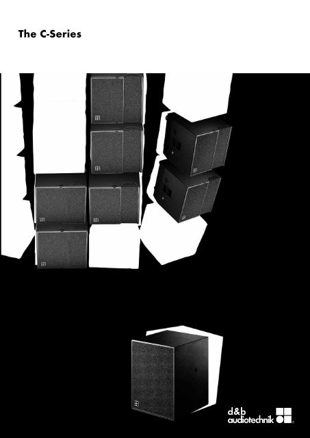
<strong>The</strong> C-<strong>Series</strong><strong>The</strong> C-<strong>Series</strong> loudspeaker range has been optimized for flexible,modular array configurations and high sound pressure levels.Applications range from professional touring use and permanentinstallations down to single cabinet setups requiring narrowdispersion with minimum dimensions. <strong>The</strong> "d&b specific"combination of a neutral, intelligible sound character that is clearand transparent even at high sound pressure levels provides theengineer with an efficient, effortless tool and a neutral platform.This is achieved through d&b’s unique design approach basedon a holistic view of the interaction between loudspeakers,electronics and mechanical accessories. Technically autonomoussystems can be combined and split in a wide variety ofcombinations. Light weight and compact sizes that take intoaccount standard truck widths result in time, space and costbenefits when transporting and installing systems. This is d&b’ssystem approach: all loudspeakers, electronics, mechanics,design tools, documentation and training, support and serviceare designed and matched for the ease of the sound designer,the system and balance engineer, the warehouse manager, theinstaller and last but not least the system owner.<strong>The</strong> C and Ci loudspeakers are designed for mobile andinstalled applications respectively, the Ci versions differing only incabinet construction and mounting hardware. <strong>The</strong> C loudspeakersare designed for a wide range of medium to large scaleapplications with a clear perspective to provide mobile, flexible,configurable array solutions to the most arduous soundreinforcement situations. <strong>The</strong> d&b TransCalc calculator predictsthe performance of arrays, enabling simple and accurate systemplanning. <strong>The</strong> Ci loudspeakers are intended for permanentlyinstalled performance spaces where the specification is riderdriven by the artist or mix engineer’s preferences. Both theCi cabinets and mounting hardware can be properly colourmatched to interior designs, are mechanically adapted forinstallation use and can provide protection in climatically hostileenvironments.C7 and Ci7-TOP are coaxial, full range loudspeakers with a75° x 40° constant directivity dispersion down to 600 Hz. <strong>The</strong>irhorn loaded 15" low frequency driver, 1.5” exit HF driver andextended bass response allow use without a subwoofer whereverfull range sound and controlled dispersion from a compactcabinet is required.C7 and Ci7-SUB are bass-reflex subwoofers with a large portand a long excursion 18” driver. <strong>The</strong>y have the same footprintas the C7 and Ci7-TOPs but are taller, allowing a frequencyextension down to 44 Hz. <strong>The</strong> C loudspeakers are ideal in aground stack of two C7-SUBs and a C7-TOP.<strong>The</strong> Ci-SUB is a bass-reflex design with an 18” driver and it isthe dedicated subwoofer for the Ci7-TOP loudspeaker for flownarray situations.<strong>The</strong> C4 system is primarily for use in medium to large-scalesound reinforcement applications and allows the construction ofscalable arrays with precise horizontal and vertical coverage.<strong>The</strong> C3, C4-TOP and C4-SUB have an identical cabinet shape,size and rigging, and along with the B2 subwoofer, form the basisof an arrayable, modular system. <strong>The</strong> 35° horizontal dispersionbehaviour of C3 and C4-TOP loudspeakers enable flawlesscoupling when array segments are combined.<strong>The</strong> C3 is a hornloaded line array module that can be arrayedboth horizontally and vertically adding a long throw capability.<strong>The</strong> unique wave front adapter couples a total of three 1.3” exitdrivers, which deliver a superbly controlled curved coherentwave front up to 16 kHz with vertical splay angles of 1° to 5°between the cabinets.<strong>The</strong> unequalled coaxial horn-in-horn design of the C4-TOPloudspeaker features an exceptionally constant and narrow35° x 35° dispersion down to 700 Hz.<strong>The</strong> C4-SUB is the flown subwoofer for the C4 system extendingthe frequency response down to 50 Hz.When deeper low frequency reproduction is required, the B2-SUBin infrabass mode can be added. As the low end of the frequencyrange is produced much more efficiently in a ground coupledconfiguration the B2 cabinet has no flying fittings.<strong>The</strong> d&b D6 and D12 dual channel amplifiers realize the completesystem. <strong>The</strong>y provide two different power ranges, incorporated&b loudspeaker specific configuration information, including theC-<strong>Series</strong> loudspeakers, the exceptions being the C3 and B2-SUBthat can only be driven by the more powerful D12. Both amplifiershave analog and digital signal inputs and links. <strong>The</strong>se devicesare specially designed and manufactured by d&b utilizing DigitalSignal Processing and include switchable functions for preciselytailoring system response for a wide variety of applications. Auser definable 4-band parametric equalizer and a delay capabilityis provided in every amplifier channel to reduce the need forexternal processing devices. <strong>The</strong> D12 amplifier additionally offersa 2-Way Active mode and a MIX TOP/SUB output configuration,output connector options as well as d&b SenseDrive.<strong>The</strong> D6 and D12 amplifiers have d&b Remote networkinterfaces enabling control and monitoring of a large number ofsystem functions and extensive system integration capabilities.d&b Load monitoring and System check are also incorporatedto remotely monitor loudspeaker driver status.To complete the picture, the C-<strong>Series</strong> maintains the d&b maximof compatibility between systems enabling them to be easilycombined with all other d&b products. Together these componentscreate complete, integrated, flexible reinforcement solutions in thesimplest to the most complex situations.4 d&b C-<strong>Series</strong>
<strong>The</strong> C-<strong>Series</strong>C7-TOP loudspeaker C7 subwoofer Ci7-TOP loudspeakerCi subwooferCi7 subwooferC4-TOP loudspeakerC4 subwooferC3 loudspeakerB2 subwooferD6 amplifierD12 amplifierd&b C-<strong>Series</strong> 5
<strong>The</strong> C7-TOP and Ci7-TOP loudspeakersC7-TOP and Ci7-TOP loudspeakers<strong>The</strong> C7 and Ci7-TOP are full range loudspeakers. <strong>The</strong> Ci7-TOPis the installation version of the C7-TOP, it differs only in cabinetconstruction and mounting hardware.<strong>The</strong> C7 and Ci7-TOP are two-way hornloaded loudspeakers,which provide full range coverage at very high SPLs. <strong>The</strong> coaxialconstant directivity design maintains a nominal dispersion of75° x 40° down to 600 Hz. <strong>The</strong> 15" LF driver is loaded with avented enclosure and passively crossed over to a 1.5" exit HFcompression driver. C7 and Ci7-TOP maintain a high efficiencyfrom 18 kHz down to 68 Hz and consequently, for applicationsthat do not demand very low frequencies additional subwoofersare not required.Where higher SPLs with sufficient bass-headroom is needed, theC7-TOP can be supplemented with two C7-SUBs for a powerfulPA, the Ci7-TOP can be supplemented with either the Ci7-SUBor Ci-SUB.<strong>The</strong> C7 and Ci7-TOP cabinets are constructed from marineplywood and have an impact resistant paint finish. <strong>The</strong> front ofthe loudspeaker cabinets are protected by a rigid metal grillcovered with a replaceable acoustically transparent foam. <strong>The</strong>C7-TOP is fitted with a pair of steel handles, MAN CF4 stud platerigging points and catches at the top and bottom for securing anoptional transport lid. Mounted on the C7-TOP rear panel arefour heavy duty wheels. Whilst the Ci7-TOP has four M12 andfour M16 threaded inserts for attaching the installation hardware.System dataFrequency response (–5 dB)................................... 68 Hz - 18 kHzMax. sound pressure (1 m, free field) 1 .............................................with D6...................................................................................134 dBwith D12................................................................................138 dBInput level (100 dB SPL /1 m)............................................–19 dBuLoudspeaker dataNominal impedance...............................................................8 ohmsPower handling capacity (RMS/peak 10 ms)............ 200/800 WNominal dispersion angle (h x v)................................... 75° x 40°Components.............................15" driver /1.5" compression driver.................................................................passive crossover networkConnections........................................................................................C7-TOP....................................................2 x EP5, optional 2 x NL4Ci7-TOP.................................................................................1 x NL4Pin assignments...................................................................................EP5...............................................................................................1/2NL4.........................................................................................1+/1–Weight.................................................................................................C7-TOP (incl. wheels)................................................52 kg (117 lb)Ci7-TOP......................................................................50 kg (110 lb)6 d&b C-<strong>Series</strong>6050403020100–10–20–30–40–50–60125 250 500 1k 2k 4k 8k 16kC7-TOP and Ci7-TOP horizontal dispersion characteristics 26050403020100–10–20–30–40–50–60125 250 500 1k 2k 4k 8k 16kC7-TOP and Ci7-TOP vertical dispersion characteristics 225˚580 [22.83"]498 [19.61"]C7-TOP cabinet dimensions in mm (inch)580 [22.83"]M16Ci7-TOP cabinet dimensions in mm (inch)1 Broadband measurement, pink noise, crest factor 4, peak measurement, linear weighting2 Dispersion angle vs frequency plotted using lines of equal sound pressure (isobars)at –6 dB and –12 dB532 [20.93"] 580 [22.83"]580 [22.83"]620 [24.41"]250 [9.84"]620 [24.41"]726 [28.58"]M12M16240 [9.45"]433 [17.05"]500 [19.68"]273 [10.75"]
<strong>The</strong> C7 and Ci7 subwoofersC7 and Ci7 subwoofersC7 and Ci7-SUB are bass-reflex subwoofers. <strong>The</strong> Ci7-SUB isthe installation version of the C7-SUB, it differs only in cabinetconstruction and mounting hardware.<strong>The</strong>y employ a long excursion 18" driver, whilst the large, speciallyshaped reflex port enables the subwoofers to achieve high soundpressure levels with minimal power compression and breathingeffects.<strong>The</strong> C7 and Ci7-SUB cabinets are constructed from marineplywood and have an impact resistant paint finish. <strong>The</strong> front ofthe loudspeaker cabinets are protected by a rigid metal grillcovered with a replaceable acoustically transparent foam. <strong>The</strong>C7-SUB is fitted with two pairs of steel handles and catches atthe top and bottom for securing an optional transport lid andan M20 threaded flange in the top panel accepts the d&bLoudspeaker stand for the deployment of full range cabinets.Mounted on the C7-SUB rear panel are four heavy duty wheels.<strong>The</strong> Ci7-SUB has two M16 threaded inserts for attaching theinstallation hardware.740 [29.13"]580 [22.83"] 620 [24.41"]726 [28.58"]System dataFrequency response (–5 dB)..........................44 Hz - 140/100 HzMax. sound pressure (1 m, free field) 1 .............................................with D6...................................................................................131 dBwith D12................................................................................135 dBLoudspeaker dataNominal impedance...............................................................8 ohmsPower handling capacity (RMS/peak 10 ms)..........400/1200 WComponents.......................................................................18” driverConnections........................................................................................C7-SUB....................................................2 x EP5, optional 2 x NL4Ci7-SUB.................................................................................1 x NL4Pin assignments...................................................................................EP5...............................................................................................3/4NL4.........................................................................................2+/2–Weight.................................................................................................C7-SUB (incl. wheels)................................................49 kg (117 lb)Ci7-SUB......................................................................45 kg (110 lb)C7-SUB cabinet dimensions in mm (inch)740 [29.1"]410 [16.1"]M16580 [22.83"] 340 [13.4"]620 [24.4"]FrontCi7-SUB cabinet dimensions in mm (inch)1 Broadband measurement, pink noise, crest factor 4, peak measurement, linear weightingd&b C-<strong>Series</strong> 7
<strong>The</strong> Ci subwooferCi subwoofer<strong>The</strong> Ci-SUB is the dedicated subwoofer for the Ci7-TOPloudspeaker for flown array situations as it shares the same size.<strong>The</strong> Ci-SUB employs a single 18“ driver. <strong>The</strong> compact bass-reflexdesign extends the low frequency response down to 44 Hz.<strong>The</strong> Ci-SUB cabinet is constructed from marine plywood and hasan impact resistant paint finish. <strong>The</strong> front of the loudspeaker cabinetis protected by a rigid metal grill, covered with a replaceableacoustically transparent foam. Four M12 and four M16 threadedinserts are provided for attaching installation hardware.580 [22.83"]580 [22.83"]M12M16240 [9.45"]340 [13.34"]500 [19.68"]System dataFrequency response (–5 dB)..........................44 Hz - 140/100 HzMax. sound pressure (1 m, free field) 1 .............................................with D6...................................................................................129 dBwith D12................................................................................133 dBM16620 [24.41"]Ci-SUB cabinet dimensions in mm (inch)Loudspeaker dataNominal impedance...............................................................8 ohmsPower handling capacity (RMS/peak 10 ms)..........400/1200 WComponents.......................................................................18“ driverConnections..........................................................................1 x NL4Pin assignments....................................................................... 2+/2–Weight.......................................................................... 39 kg (86 lb)1 Broadband measurement, pink noise, crest factor 4, peak measurement, linear weighting8 d&b C-<strong>Series</strong>
<strong>The</strong> C4-TOP loudspeakerC4-TOP loudspeaker<strong>The</strong> C4-TOP is a two-way hornloaded loudspeaker, which providesmid to high range coverage at very high SPLs. <strong>The</strong> coaxial constantdirectivity design maintains a nominal dispersion of 35° x 35°down to 700 Hz. <strong>The</strong> 12" LF driver with a 4” voice coil andspecially treated diaphragm is passively crossed over to a 2" exitHF compression driver.<strong>The</strong> C4-TOP cabinet is constructed from marine plywood, fittedwith steel handles, MAN CF4 stud plate rigging points and has animpact resistant paint finish. <strong>The</strong> front of the loudspeaker cabinetis protected by a rigid metal grill, covered with a replaceableacoustically transparent foam and fitted with catches at the topand bottom for securing an optional transport lid. Mounted onthe rear panel are ratchet strap guide plates (kelping bars), fourM10 threaded inserts for attaching installation hardware andfour heavy duty wheels.System dataFrequency response (–5 dB).................................150 Hz - 18 kHzMax. sound pressure (1 m, free field) 1 .............................................with D6...................................................................................136 dBwith D12................................................................................140 dBInput level (100 dB SPL /1 m)............................................–21 dBuLoudspeaker dataNominal impedance...............................................................8 ohmsPower handling capacity (RMS/peak 10 ms)............ 200/800 WNominal dispersion angle (h x v)................................... 35° x 35°Components...12” driver with 4” voicecoil /2” compression driver.................................................................passive crossover networkConnections...................................................2 x EP5, optional NL4Pin assignments...................................................................................EP5...............................................................................................1/2NL4........................................................................................ 1+/1–Weight (incl. wheels).................................................58 kg (128 lb)6050403020100–10–20–30–40–50–60125 250 500 1k 2k 4k 8k 16kC4-TOP horizontal/vertical dispersion characteristics 215º580 [22.83"]498 [19.61"]463 [18.22"] 580 [22.83"]235 [9.25"]C4-TOP cabinet dimensions in mm (inch)620 [24.41"]726 [28.58"]433 [17.05"]1 Broadband measurement, pink noise, crest factor 4, peak measurement, linear weighting2 Dispersion angle vs frequency plotted using lines of equal sound pressure (isobars)at –6 dB and –12 dBd&b C-<strong>Series</strong> 9
<strong>The</strong> C4 subwooferC4 subwoofer<strong>The</strong> C4-SUB is a compact, double band pass subwoofer employinga single 18" driver. It is designed for use with the C3 and C4-TOPcabinets as part of the C4 system.<strong>The</strong> C4-SUB cabinet is constructed from marine plywood, fittedwith steel handles, MAN CF4 stud plate rigging points and has animpact resistant paint finish. <strong>The</strong> front of the loudspeaker cabinetis protected by a rigid metal grill, covered with a replaceableacoustically transparent foam and fitted with catches at the topand bottom for securing an optional transport lid. Mounted onthe rear panel are ratchet strap guide plates (kelping bars) andfour heavy duty wheels.System dataFrequency response (–5 dB)...................................50 Hz - 150 HzMax. sound pressure (1 m, free field) 1 .............................................with D6...................................................................................131 dBwith D12................................................................................135 dB15º580 [22.83"]498 [19.61"]463 [18.22"] 580 [22.83"]235 [9.25"]C4-SUB cabinet dimensions in mm (inch)620 [24.41"]726 [28.58"]433 [17.05"]Loudspeaker dataNominal impedance...............................................................8 ohmsPower handling capacity (RMS/peak 10 ms)............ 200/800 WComponents.......................................................................18” driverConnections............................................2 x EP5, optional 2 x NL4Pin assignments...................................................................................EP5......................................................................3/4, SenseDrive: 5NL4.........................................................................................2+/2–Weight (incl. wheels).................................................48 kg (106 lb)1 Broadband measurement, pink noise, crest factor 4, peak measurement, linear weighting10 d&b C-<strong>Series</strong>
<strong>The</strong> C3 loudspeakerC3 loudspeaker<strong>The</strong> C3 is the hornloaded line array module for the C4 system.<strong>The</strong> C3 cabinet houses 2 x 10" midrange drivers and 3 x 1.3" exitHF compression drivers with titanium diaphragms, producing amaximum sound pressure level of 144 dB SPL. Utilizing a horizontaldispersion of 35° (above 900 Hz) and with a 5° vertical HFdispersion per cabinet, the C3 is used to build vertical columnsproducing a curved coherent wavefront.<strong>The</strong> C3 cabinet is constructed from marine plywood, fitted withsteel handles, MAN CF4 stud plate rigging points and has animpact resistant paint finish. <strong>The</strong> front of the midrange section ofthe loudspeaker cabinet is protected by a rigid metal grill fittedwith a replaceable acoustically transparent foam, and the HFsection is fitted with a foam block in the horn throat. Catches arefitted at the top and bottom of the cabinet for securing an optionaltransport lid. Mounted on the rear panel are ratchet strap guideplates (kelping bars), two hinge plates and four heavy dutywheels.System dataFrequency response (–5 dB standard)............... 130 Hz - 16 kHz 1Frequency response (–5 dB LFC mode)................80 Hz - 16 kHz 1Max. sound pressure (1 m, free field) 2 .............................................with D12................................................................................144 dBLoudspeaker dataNominal impedance (MF/HF)............................ 4 ohms /5.3 ohmsPower handling capacity LF (RMS/peak 10 ms)......500/2000 WPower rating HF (RMS/peak 10 ms)...........................150 /600 WNominal dispersion angle (h x v)......................................35° x 5°Components.............2 x 10" drivers /3 x 1.3" compression driversConnections............................................1 x EP5, optional 1 x NL4Pin assignments...................................................................................EP5....................................................................... MF: 1/2, HF: 3/4NL4............................................................ MR: 1+/1–, HF: 2+/2–Weight (incl. wheels).................................................71 kg (156 lb)9080706050403020100–10–20–30–40–50–60–70–80–90125 250 500 1k 2k 4k 8k 16kC3 horizontal dispersion characteristics 315580 [22.83"]498 [19.61"]463 [18.22"] 580 [22.83"]C3 cabinet dimensions in mm (inch)235 [9.25"]620 [24.41"]726 [28.58"]433 [17.05"]1 Two cabinets2 Broadband measurement, pink noise, crest factor 4, peak measurement, linear weighting3 Dispersion angle vs frequency plotted using lines of equal sound pressure (isobars)at –6 dB and –12 dBd&b C-<strong>Series</strong> 11
<strong>The</strong> B2 subwooferB2 subwoofer<strong>The</strong> B2-SUB is a dual mode 2 x 18” double band pass subwoofer,configurable either for infrabass with the C4 system or as a highoutput alternative subwoofer. When used with a C4 system, d&brecommend a ratio of four C4-SUBs to one B2-SUB.<strong>The</strong> B2-SUB cabinet is constructed from marine plywood and hasan impact resistant paint finish. <strong>The</strong> front of the loudspeakercabinet is fitted with a rigid metal grill, covered with a replaceableacoustically transparent foam and fitted with catches at the topand bottom for securing an optional transport lid. <strong>The</strong> cabinetincorporates eight steel handles and four heavy duty wheels.1160 [45.67"]580 [22.83"]B2-SUB cabinet dimensions in mm (inch)920 [36.22"]1046 [41.18"]System data (standard/INFRA)Frequency response (–5 dB)....... 37 Hz - 100 Hz /32 Hz - 68 HzMax. sound pressure (1 m, full space) 1 ............................................with D12................................................................ 139 dB /136 dBLoudspeaker dataNominal impedance...............................................................4 ohmsPower handling capacity (RMS/peak 10 ms)..........600/2400 WComponents................................................................2 x 18” driverConnections...................................................1 x EP5, optional NL8Pin assignments...................................................................................EP5......................................................................3/4, SenseDrive: 5NL8..............................................................4+/4–, SenseDrive: 3–Weight (incl. wheels).............................................. 102 kg (225 lb)rearfrontCSA configuration example901206015030180 0210330240270Cardioid polar pattern3001 Broadband measurement, pink noise, crest factor 4, peak measurement, linear weighting12 d&b C-<strong>Series</strong>
<strong>The</strong> C7/C4/C3 rigging accessories and examplesSafety approvald&b loudspeakers and accessories are designed for set up anduse within situations requiring compliance with the provisions anddirectives of BGV C1 Rule for the Prevention of Accidents.354122613646577Z5017TV spigot HDZ5090Single bar assembly withZ5017TV spigot HDZ5090 Single bar (1) withE6512 2t Shackle (2)E6507 1t Shackle (3)E6511 Delta link (4)E6510 2t Ratchet strap (5)E652x 1t Chains (6)Z5040 Flying stud (7)E6521 1t Chain 23 links (1)Z5040 Flying stud (2)E6507 1t Shackle (3)E6511 Delta link (4)E6510 2t Ratchet strap (5)Z5110 Hinge (6)Z5040Flying studE65102t Ratchet strap black12 m /39.4 ft.12E652x1t Chains various length (1)E65341t Shortening chain 47 links (2)E6524Vari-chain (3)3Z5110HingeZ5073 d&b Transformer 2 wide with theZ5072 Spreader bar used to combine systems 4 wide or greaterd&b C-<strong>Series</strong> 13
<strong>The</strong> Ci7-TOP/SUB and Ci-SUB mounting accessoriesSafety approvald&b loudspeakers and accessories are designed for set up anduse within situations requiring compliance with the provisions anddirectives of BGV C1 Rule for the Prevention of Accidents.Z5148Ci Mounting bracketZ5091Ci Flying bracketZ5018TV spigot M12Q9030Safety eyebolt M12Q9034Safety eyebolt M1614 d&b C-<strong>Series</strong>
<strong>The</strong> Ci7-TOP/SUB and Ci-SUB mounting examplesCi7-TOP withZ5148 Ci Mounting bracketZ5148Ci Mounting bracket assemblyCi7-TOP withZ5091 Ci Flying bracketQ9030 Safety eyebolt M12Z5091Ci Flying bracket assemblyd&b C-<strong>Series</strong> 15
<strong>The</strong> Ci7-TOP and Ci-SUB mounting system<strong>The</strong> d&b Ci Mounting system is specially designed for use withthe d&b installation loudspeakers Ci7-TOP and Ci-SUB.A pair of mounting brackets [2] enable two cabinets to bevertically arrayed with a defined range of angles between them.<strong>The</strong>re are three sets [2(a, b, c)], each set enabling a differentrange of angle settings between the cabinets.<strong>The</strong> Z5145 Ci Mounting frame [1] is used to suspend the cabinetseither at the centre plate or left and right using the outer plates.<strong>The</strong> entire cluster can be vertically aligned, depending on whichof the locating holes of the mounting frame is used. <strong>The</strong> Z5147Rota clamp [3a] enables the horizontal alignment of the clusterby suspending it from a single flying point using the centre plateof the mounting frame. <strong>The</strong> Rota clamp can be attached tooverhead bars or truss with a tube diameter up to 51 mm (2”).Alternatively the Z5145 Ci Mounting frame can be suspendedat the outer plates using shackles and steel wire ropes [3b].<strong>The</strong> Ci Mounting system is constructed from powder coated steel.[1]→←[3a]←[3b]←[2 (a, b, c)]Ci Mounting system[2a] [2b] [2c]Z5146.015 Ci Mounting bracketsfor vertical splay 0° to 15°Z5146.030 Ci Mounting bracketsfor vertical splay 12° to 30°Z5146.045 Ci Mounting bracketsfor vertical splay 28° to 45°16 d&b C-<strong>Series</strong>
<strong>The</strong> Ci loudspeakers Weather Resistant andSpecial Colour options<strong>The</strong> Weather Resistant and Special Colour options are onlyavailable to order with the Ci version cabinets.Weather Resistant (WR) option<strong>The</strong> WR option enables operation of loudspeakers in changingambient conditions, however it is not intended to enable permanent,unprotected operation of loudspeakers outdoors. Cabinets beingused outdoors even with the WR option should always be aimedeither horizontally or with a downward tilt. An additional covershould be positioned over the loudspeakers.Ci loudspeakers with the Weather Resistant option are suppliedwith a fixed cable. Cable type H-07-RN-F 2 x 2.5 mm 2 /AWG 13with a length of 5.5 m (18 ft) as standard or length as required.Special Colour (SC) RAL paint option<strong>The</strong> paint finish of all loudspeaker cabinets and most accessoriescan be executed in almost all RAL colours in accordance with theRAL colour table. Items such as chains, fixing screws, shackles,eyebolts and screws are not painted. Other paint finishes such asmetallic are available on request. <strong>The</strong> acoustically transparentfoam is also painted with the requested RAL colour.d&b C-<strong>Series</strong> 17
VOLTAGE SEE LABEL~ 50/60 Hz, 1000 W<strong>The</strong> D6 and D12 amplifiers<strong>The</strong> D6 and D12 are dual channel amplifiers developed andmanufactured by d&b utilizing Digital Signal Processing (DSP) toincorporate loudspeaker specific configuration information andfunctions. <strong>The</strong>se are designed for use with d&b loudspeakers,have both digital and analog signal inputs as well as link outputs,remote control and monitoring capabilities and switch mode powersupplies. <strong>The</strong> level control incorporates a digital rotary encoderenabling selection of all operating modes in conjunction with aLiquid Crystal Display (LCD).Loudspeaker specific configurations for current d&b loudspeakersand a linear mode are contained within them, the exceptionbeing that the D6 does not include 2-Way Active, V-<strong>Series</strong> andB2-SUB configurations.<strong>The</strong> digital elements of the D6 and D12 are specified andconstructed to achieve the best possible audio performance whilemaintaining a very low latency of 0.3 msec. <strong>The</strong> Digital SignalProcessing is used to provide the loudspeaker specific configurations,sophisticated protection circuits modelling thermal and mechanicaldriver behaviour, and switch functions.User definable equalization and delay functions are incorporatedin each channel of the amplifiers and can be used for applicationssuch as front fills or under balcony delays without the need forexternal processors. <strong>The</strong> signal delay capability allows delaysettings of up to 340 msec. (= 100 m/328 ft) to be appliedindependently to each channel as can the 4-band parametricequalizer, providing optional Boost/Cut or Notch filtering. Asignal generator offering pink noise or sine wave program is alsoincorporated for test and alignment purposes. Every unit can begiven a unique Device Name to simplify identification and apassword protected LOCK function is also incorporated to preventunauthorized changes.<strong>The</strong> D6 and D12 amplifiers also detect incoming Pilot signals atits input (Input monitoring) and can use Load monitoring andSystem check functions to determine the status of the loudspeakerimpedance. d&b System check is designed to verify that thesystem performs within a predefined condition and can be usedto report the system condition after a show.d&b Load monitoring, on the other hand, enables automatic andcontinuous impedance monitoring and along with Input monitoringis designed for incorporation within applications specified to therequirements stated in the International Standard IEC 60849‘Sound Systems for Emergency Purposes’. Both can determine thestatus of an LF or HF driver in systems with multiple elements,even if these are crossed over passively.<strong>The</strong> D6 utilizes a switch mode power supply with PFC suitable formains supply voltages 100 V/115 V/200 V/230 V, 50 - 60 Hzwhilst the D12 utilizes an autosensing switch mode power supplyfor mains voltages 115/230 V, 50 - 60 Hz (optional 100/200 V).Both power supplies have overvoltage protection and eachamplifier has a temperature and signal controlled fan to cool theinternal assemblies.<strong>The</strong> 2 RU lightweight D6 is specifically designed to deliver mediumpower into low impedance loads between 4 and 16 ohms. <strong>The</strong>3 RU D12 is specifically designed to produce high power intolow impedance loads, typically those between 4 and 16 ohms.Due to differences in impedance response against frequency, themaximum number of cabinets driven by each D12 channel variesdepending on the loudspeaker type.Apart from selectable output configurations for dual channel, MixTOP/SUB and 2-Way Active mode, the D12 also provides d&bSenseDrive for use with the LF drivers in d&b active loudspeakersand subwoofers.Both amplifiers house an I/O panel containing: analog signalinputs with link outputs for each channel, an AES/EBU digitalinput with a link output and NL4 loudspeaker outputs. <strong>The</strong> D12I/O panel additionally offers the options of EP5 or NL8loudspeaker outputs. <strong>The</strong> two RJ 45 REMOTE sockets at the rearof the D6 and the D12 amplifiers integrate them into the d&bRemote network via CAN-Bus, enabling remote control and/ormonitoring.A USB-B (D6) or a SUB-D9 (D12) SERVICE interface is providedto enable future firmware updates containing new loudspeakerconfigurations or additional functions to be loaded to the units.D6MAINS SUPPLYCH ADIGITAL AES/EBU ANALOGOUTAOUTBREMOTESERVICECH BD6 rear viewD12 rear view18 d&b C-<strong>Series</strong>
<strong>The</strong> D6 and D12 amplifier dataD6 DisplayISP, GR, OVL A/B........................................................LED indicatorsLiquid Crystal Display (LCD).........Graphic display/120 x 32 PixelD6 ControlsPOWER, MUTE/LEVEL..................................Switch, rotary encoderFunction switches..................................Loudspeaker specific circuits4-band equalizer.............................................Optional PEQ/NotchDelay setting........................0.3 - 340 msec. with 0.1 msec. detentsConfigurations..............Current d&b loudspeakers and linear mode......................................except 2-Way Active, V-<strong>Series</strong> and B2-SUBFrequency generator....................................Pink noise or Sine waveD6 ConnectorsINPUT/LINK ANALOG A/B......................3 pin XLR female/male 1INPUT/LINK DIGITAL AES/EBU................3 pin XLR female/male 1Sampling rate..........................................................48 kHz /96 kHzOUT CHANNEL A/B..................................................................NL4REMOTE................................................................2 x RJ 45 parallelSERVICE..........................................................................USB Type BD6 Protection circuitsMains inrush current limiter..............................1.5 A RMS at 230 VLoudspeaker switch on delay.....................................Approx. 2 sec.Overvoltage protection.............................................Up to 400 VACD6 Data (linear setting with subsonic filter)Rated output power (THD+N < 0.1%)..........................................................................2 x 350 W into 8 ohms, both channels are driven............................2 x 600 W into 4 ohms, both channels are drivenS/N ratio (unweighted, RMS)...........................................>110 dBrD6 Digital Signal ProcessingSampling rate...............................96 kHz/27 Bit ADC/24 Bit DACBasic delay/latency analog input.....................................0.3 msec.D6 Power supplySwitch mode power supply for............................................................................................................100/115/200/230V, 50 - 60 HzMains connector...........................................................PowerCon ® 2D6 Remote networkRemote network...................................................................CAN-BusD6 Dimensions, weightHeight x width x depth........................2 RU x 19” x 353 mm/13.9”Weight..........................................................................8 kg/17.6 lbD12 DisplayISP, GR, OVL A/B.......................................................LED indicatorsLiquid Crystal Display (LCD).........Graphic display/120 x 32 PixelD12 ControlsPOWER, MUTE/LEVEL..................................Switch, rotary encoderFunction switches..................................Loudspeaker specific circuits4-band equalizer.............................................Optional PEQ/NotchDelay setting........................0.3 - 340 msec. with 0.1 msec. detentsConfigurations..............Current d&b loudspeakers and linear modeFrequency generator....................................Pink noise or Sine waveD12 ConnectorsINPUT/LINK ANALOG A/B.......................3 pin XLR female/male 1INPUT/LINK DIGITAL AES/EBU................3 pin XLR female/male 1Sampling rate..........................................................48 kHz /96 kHzOUT CHANNEL A/B................................Optional EP5/NL4/NL8REMOTE................................................................2 x RJ 45 parallelSERVICE....................................................................SUB-D9 femaleD12 Protection circuitsMains inrush current limiter..................................5 A RMS at 230 VLoudspeaker switch on delay.....................................Approx. 2 sec.Overvoltage protection.............................................Up to 400 VACD12 Data (linear setting with subsonic filter)Rated output power (THD+N < 0.1%)..........................................................................2 x 750 W into 8 ohms, both channels are driven.........................2 x 1200 W into 4 ohms, both channels are drivenS/N ratio (unweighted, RMS)............................................>110 dBrD12 Digital Signal ProcessingSampling rate................................96 kHz/27 Bit ADC/24 Bit DACBasic delay/latency analog input......................................0.3 msec.D12 Power supplyAutosensing switch mode power supply for...........................................................................................................115/230 V, 50 - 60 Hz......................................................optional 100/200 V, 50 - 60 HzMains connector...........................................................PowerCon ® 2D12 Remote networkRemote network...................................................................CAN-BusD12 Dimensions, weightHeight x width x depth........................3 RU x 19” x 353 mm/13.9”Weight...........................................................................13 kg/29 lb1 XLR pin assignment analog, inputs and links: 1 = GND, 2 = pos. signal, 3 = neg. signalXLR pin assignment digital, input and link: 1 = GND, 2 = signal, 3 = signal2 PowerCon ® is a registered trademark of the Neutrik AG, Liechtensteind&b C-<strong>Series</strong> 19
<strong>The</strong> operation with D6 and D12 amplifiersOperation with D6 and D12C7/Ci7-TOP C7/Ci7-SUB Ci-SUB C4-TOP C4-SUB B2-SUBMax. LS per channel 2 2 2 2 2 1Maximum loudspeakers per D6 or D12 channel2-Way Active operation with D12C3Max. LS per D12 2Maximum loudspeakers per D12D6 and D12 controller settingsC7/Ci7-TOP C7/Ci7-SUB Ci-SUB C4-TOP C4-SUB C3 B2-SUBCUTxHFAxCPL x x x100 Hz x xHFC x x+B2 xLFCxINFRAxCSAxD6 and D12 controller settings for each loudspeaker20 d&b C-<strong>Series</strong>
<strong>The</strong> operation with D6 and D12 amplifiersCUT modeSet to CUT, the cabinet low frequency level is reduced and isconfigured for use with d&b active subwoofers.HFA modeIn HFA mode (High Frequency Attenuation), the HF response ofthe system is rolled off. <strong>The</strong> HFA provides a natural, balancedfrequency response when a unit is placed close to listeners innear field or delay use. HFA begins gradually at 1 kHz, droppingby approximately 3 dB at 10 kHz. This roll off mimics the declinein frequency response experienced when listening to a systemfrom a distance in a typically reverberant room or auditorium.CPL function<strong>The</strong> CPL (Coupling) function compensates for coupling effectsbetween closely coupled cabinets by reducing the low and midfrequency level. CPL begins gradually at 1 kHz, with maximumattenuation below 250 Hz (400 Hz for the C3), providing abalanced frequency response when cabinets are used in arraysof two or more. <strong>The</strong> CPL function can be set in dB attenuationvalues between –9 and 0, or in the case of the C7 and Ci7-TOPan optional boost between 0 and +5 around 65 Hz can be set.100 Hz modeIf the 100 Hz mode is selected, the upper operating frequencyof the system is reduced to 100 Hz. This setting allows thesubwoofer to supplement top cabinets in full range mode.HFC modeSelecting the HFC (High Frequency Compensation) modecompensates for loss of high frequency energy due to absorptionin air when loudspeakers are used to cover far field listeningpositions. HFC should be used selectively, only for those cabinetscovering distances of approximately 30 m (100 ft) for theC4-TOP and 50 m (160 ft) for the C3. This enables the correctsound balance between close and remote audience areas, whilstall amplifiers driving the array can be fed with the same signal.LFC modeIn LFC mode (Low Frequency Compensation), the low frequencyresponse is extended down to 80 Hz for speech reinforcementwithout subwoofers.INFRA modeSelecting the INFRA mode restricts the B2 frequency response toa narrow, 32 Hz - 68 Hz range (–5 dB). This transforms a B2into an infrabass system for use with C or Q-<strong>Series</strong> loudspeakers.CSA modeCSA (Cardioid Subwoofer Array) mode enables the combinationof three or multiples of three subwoofer cabinets into an arraythat produces exceptional low frequency directivity control. <strong>The</strong>centre cabinet in a column is physically pointed to the rear andthe CSA mode selected on the D6 or D12 channel that powersthis cabinet. <strong>The</strong> forward facing cabinets are driven with a D6or D12 channel set in the standard mode. <strong>The</strong> resulting cardioidbehaviour of the array will significantly reduce the energyradiated to the rear. For further information please refer to thed&b TI 330 Cardioid Subwoofer Array, which is available fordownload at www.dbaudio.com.d&b SenseDrive<strong>The</strong> D12 incorporates d&b SenseDrive for accurate control ofLF drivers in d&b loudspeakers driven 2-Way Active or in d&bsubwoofers driven actively, resulting in an extremely precise bassperformance, even at high levels. SenseDrive is only availableusing a D12 fitted with EP5 connectors and appropriate 5-wirecabling. For further information please refer to the d&b TI 340SenseDrive, which is available for download at www.dbaudio.com.+B2 mode<strong>The</strong> +B2 mode increases the headroom of the C4-SUBs whenused with additional B2 subwoofers set to INFRA mode. Thisintroduces a relatively narrow-band signal attenuation around50 Hz raising the lower frequency limit of the C4-SUB to around60 Hz. <strong>The</strong> C4-SUB’s headroom is increased, while the combinedsystem response will not change significantly.d&b C-<strong>Series</strong> 21
<strong>The</strong> C-<strong>Series</strong> frequency responses10105500-5-5-10-10-15-15-20-20-25-25-3020 100 1k 10k 20kC7/Ci7-TOP standard, CUT and HFA-3020 100 1k 10k 20kC7/Ci7-SUB standard and 100 Hz10105500-5-5-10-10-15-15-20-20-25-25-3020 100 1k 10k 20kCi-SUB standard and 100 Hz-3020 100 1k 10k 20kC4-TOP standard10105500-5-5-10-10-15-15-20-20-25-25-3020 100 1k 10k 20kC4-SUB standard-3020100 1k 10k 20kC3 standard, LFC and HFC (single cabinet)1050-5-10-15-20-25-3020100 1k 10k 20kB2-SUB standard and INFRA22 d&b C-<strong>Series</strong>
<strong>The</strong> C4 system with C3 loudspeakersVertical array of C4 and C3 cabinetsAs their horizontal dispersion behaviour is identical, C4-TOP andC3 cabinets can be easily combined in one array.<strong>The</strong> larger vertical dispersion of a C4-TOP can be used efficientlyto cover the near field in front of a C3 column. A vertical splayof 5° or 10° to the lowest C3 is useful, depending on the totalheight of the system.Horizontal array of C4 and C3 cabinets<strong>The</strong> horizontal angle between adjacent C4 and/or C3 cabinetsin an array can be set to between 20° and 30°.<strong>The</strong> most even and widest energy distribution is achieved with30°. Smaller angles between the cabinets will give a smallerhorizontal coverage area but will produce higher sound pressureon the centre axis of the array. <strong>The</strong> configuration of any arrayshould be thoroughly adapted to the actual venue room acousticsand requirements. In order to keep diffuse sound low, the totalcoverage angle should only be as wide as necessary to coverthe audience area.Operation with C4-SUB and B2-SUBC4-SUBs should be used to extend the C4-TOP and C3 frequencyresponse. Forming columns of SUB cabinets improves efficiencyand vertical directivity at low frequencies. For a balanced soundat high levels a ratio of at least one C4-SUB per C3 or C4-TOPcabinet is required. For a further extension of bandwidth andheadroom ground stacked B2 subwoofers are used (INFRAmode).0°-30° 0° 0° +30°C4-SUBC4-SUBFarfieldC3C4-SUBExample setup<strong>The</strong> example opposite shows a C4/C3 setup arranged to providethe coverage and level distribution for a simple rectangularaudience area. <strong>The</strong> central C3 column projects energy to thefar field with a 40° horizontal coverage angle, the C4-TOPcabinets lower down in the cluster provide the wider horizontalcoverage angle required in the near field. <strong>The</strong> C3s in the innercolumn cover the mid field and the mixing position, while thecolumn of C4-SUBs maintains a consistent vertical directivity inthe lower frequencies.-1°-3.5°-8.5°-18.5°C4-SUBC4-TOPC4-SUBSidefieldC4-SUBC4-SUBC4-SUBC3C3C3Near fieldC4-SUBC3C3C4-TOP C4-SUB C4-TOP C4-TOPMidfieldd&b C-<strong>Series</strong> 23
<strong>The</strong> D6 and D12 amplifiers installation<strong>The</strong> diagram opposite shows the thermal operating range withinwhich the technical data will be maintained. <strong>The</strong> operationbeyond this range is possible for a short time but for thermalreasons this may trigger the amplifier protection circuit forthermal overload.<strong>The</strong> D6 and D12 amplifier enclosures are designed to fit astandard 19" equipment rack or cabinet.When specifying a rack, be sure to allow extra depth (10 cm /4"is usually sufficient) to accommodate the cables and connectorsat the rear of the amplifier(s). When mounting amplifiers into a19" rack cabinet, provide additional support using shelves fixedto the inner sides of the cabinet or the mounting holes providedon the amplifier rear mounted rack ears; do not just rely on fixingand supporting amplifiers by their front panels.Since the amplifiers can generate a lot of heat, please ensure,whatever the mounting or racking arrangement, that adequatecool airflow is provided to avoid a build-up of hot air inside therack leading to overheating. When setting up the amplifier, donot block or cover the rear panel air intake or the vents on thefront panel of the amplifier.If amplifiers are installed in cabinets so that direct access to therear panel filters is not possible, we recommend using additionalfan modules with front mounted filters that can be easily replacedwithout opening the sealed cabinets.Max. average output Power [W]900800 D12700600500400 D630020010000 5 10 15 20 25 30 35 40 45Ambient Temp. in CTotal average output power vs. ambient temperature24 d&b C-<strong>Series</strong>
<strong>The</strong> D6 and D12 amplifiers installationD6483 [19.00"]443 [17.44"]338 [13.31"]D12483 [19.00"]338 [13.31"]443 [17.44"]324 [12.56"]348 [13.70"]132 [5.2"]5 [0.2"]3 [0.12"]324 [12.56"]348 [13.70"]88 [3.46"]D6 enclosure dimensions in mm [inch]D12 enclosure dimensions in mm [inch]Airflow directiond&b C-<strong>Series</strong> 25
<strong>The</strong> D6 and D12 amplifierspower consumption and power lossD6 and D12 power consumption and power loss<strong>The</strong> power required from the mains supply and the waste heatproduced by the amplifier power loss vary depending on the loadimpedance and the signal levels and characteristics (e.g. speech,music). In practice, the theoretical peak power consumption of asystem will only be sustained for a short period of time. Basingmains current and air conditioning plant requirements on thepeak power consumption of the sound system would result in agenerously overspecified installation. <strong>The</strong> key factor in powerconsumption calculations is the crest factor of the music or speechsignal – the ratio of peak to sustainable RMS voltage of thesignal.<strong>The</strong> table opposite gives power figures for various types of signalwaveforms.Mains supplyMaximum number of devices per phase conductor when full outputpower is required.Mains supplyMax. number of devicesD6D12230 V/16 A 4 2115 /100 V/15 A 2 1In the USA and Japan we recommend the operation over twophase conductors (phase to phase – 240 /200 V) or the use ofmains leads with a much higher cross section.26 d&b C-<strong>Series</strong>
<strong>The</strong> D6 and D12 amplifierspower consumption and power lossSignal waveform CF Duty Pout [W] Pin [W] Ploss [W] Iin [A] Uin [V]1560 360 6.8 230Sine wave 1.4 1/1 1200 1645 445 14.3 1151715 515 17.2 100Highly 520 120 2.3 230compressed 2.4 1/3 400 550 150 4.8 115music 1 570 170 5.7 100Music with 215 65 1.0 230low dynamic 4.0 1/8 150 220 70 2.0 115range 220 70 2.2 100D6 Power balanceSignal waveform CF Duty Pout [W] Pin [W] Ploss [W] Iin [A] Uin [V]20.6 2 230Sine wave 1.4 1/1 2400 3480 1080 41.2 2 11547.4 2 100Highly 9.2 230compressed 2.4 1/3 800 1230 430 18.4 2 115music 1 20.2 2 100Music with 5.3 230low dynamic 4.0 1/8 400 640 240 10.6 115range 11.2 100D12 Power balanceKey:CF: Crest factor, Duty: Duty cycle, Pout [W]: Max. average output power (sum of both channels), Pin [W]: Input power (effective power)Ploss: Power loss (thermal power), Iin [A]: Resulting current, Uin [V]: Mains voltage1 Maximum practicable operation2 Only in conjunction with appropriate mains power supply installationd&b C-<strong>Series</strong> 27
<strong>The</strong> d&b Remote networkd&b Remote network<strong>The</strong> d&b Remote network enables central control and monitoringof a complete d&b loudspeaker system from anywhere in thenetwork, be it from a PC in the control room, at the mix position,or on a wireless tablet PC in the auditorium.This central access to all functions, controls and detailed systeminformation unlocks the full potential of the d&b system approach.Extensive monitoring and diagnostics enable detailed examinationof the system performance. Control can be undertaken on individualloudspeakers, on multiple groups of loudspeakers or formed intogroups that address the complete system.<strong>The</strong> flexibility and scalability of this approach, coupled with theinclusion of several types of interfaces, allow the d&b Remotenetwork to be deployed to address the differing control andmonitoring requirements in a broad variety of mobile andinstalled applications, regardless of their size.In mobile applications, system engineers may use the remotenetwork to verify and tune the system. System check and devicediagnostics enable detailed monitoring as and when required,before, during, or after a show.In installation projects system integrators can configure the remotenetwork to offer access to different levels of control tailored tothe operational demands. For example, simplified functionality fordaily use and more complex functionality when multiple applicationsare required within one installation. Input and Load monitoringcoupled with automatic error messages allow installation operatorsto ensure the optimum performance at all times.TerminatingconnectorDaisy chaind&b Remote networkZ6118 R60 USB to CAN interfaceD6D6D6CAN-BusCAN-BusInterfaceComputer runningR1 or R10d&b Remote interfacesEvery d&b amplifier is fitted with a Remote interface for theController Area Network (CAN) Bus. Each D6 and D12 has twoREMOTE connectors (RJ 45) to enable the CAN-Bus signal tobe daisy chained through them. A simple d&b Remote networkapplication consists of a computer running R1 Remote controlsoftware, an R60 USB to CAN interface, CAT 5 shielded twistedpair cable with shielded RJ 45 connectors and d&b D6 or D12amplifiers.Up to five R60 USB to CAN interfaces can be operated with onecomputer running R1, while a maximum of 504 amplifiers can beincorporated into one application. <strong>The</strong> maximum bus cable lengthof a d&b Remote network is 600 metres, see the adjoining tablefor cable length examples. <strong>The</strong> R70 Ethernet to CAN interface canbe used for applications over longer distances, in conjunction witha fibre optic network for example.For further information about CAN-Bus cabling requirements andinterfaces please refer to the d&b TI 312 d&b Remote network,which is available for download at www.dbaudio.com.Z6124 R70 Ethernet to CAN interfaceCable crosssection0.25 mm 2 (24 AWG)0.75 mm 2 (18 AWG)Examples of bus cable lengthMaximum bus cable lengthwith numbers of amplifiers32 100180 m (600 ft) 140 m (460 ft)500 m (1650 ft) 330 m (1100 ft)28 d&b C-<strong>Series</strong>
<strong>The</strong> d&b Remote softwareR1 Remote control softwareR1 Remote control software is a graphical drag and drop userinterface enabling the construction of a screen based virtualcontrol surface for d&b systems, using the d&b Remote network.All major features, functions and controls available on the frontpanel of the D6 and D12 amplifiers may be remotely controlledand/or monitored using R1. <strong>The</strong> architecture of R1 allows controlof each channel of the amplifier as a single entity and enablesthe creation of groups of loudspeakers in as little, or as muchdetail as required by the user. When grouped together, a button orfader can control the overall system level, zone level, equalizationand delay, power ON/OFF, MUTE and loudspeaker functionswitches such as CUT/HFA/HFC or CPL.R1 has extensive facilities for storing and recalling system settingsallowing these to be repeated, as and when required. It is easy toadjust R1 project files for use with a different set of equipment atanother location. Password protection is available to restrictaccess.R1 runs on PCs operating Microsoft Windows XP SP3/Vista SP1/7 1 .A virtual machine enables R1 to run on the newer Intel 2 Mac 3 inparallel to the Mac OS 3 X, using the Windows driver for R60USB to CAN interface.For older, Power PC based Mac computers, Windows emulationneeds to be used, together with the R60 driver for Mac/PPC. ForR70 Ethernet to CAN, no driver is needed.All the latest available drivers, R1 example files that can be usedas templates and the TI 391 describing the effective use of R1are available for download at www.dbaudio.com.R1 main page, groups and master controlsR10 Service softwareR10 Service software enables the simultaneous firmware updateof multiple amplifiers from a central location. Using R10,AmpPresets can be adjusted to the application requirements.R1 device page, individual devices, details view andgroup controlsIntegration with media controlFor integration of d&b audiotechnik loudspeaker systems intomedia control applications, the R70 Ethernet to CAN interfaceis used. Media control modules (drivers) are available atwww.dbaudio.com.EN 60849 voice alarm applicationsFor remote control of voice alarm applications ProgrammableLogic Controllers (PLCs) can be integrated into the d&b Remotenetwork.1 Microsoft and Windows XP/Vista/7 are either registered trademarks or trademarksof Microsoft Corporation in the United States and/or other countries2 Intel is a trademark of the Intel Corporation in the United States and other countries3 Mac and Mac OS are trademarks of Apple Inc., registered in the United States andother countriesR1 equalizer paged&b C-<strong>Series</strong> 29
<strong>The</strong> C-<strong>Series</strong> product overviewCodeDescriptionC loudspeakers Z2257.002 C7-TOP Loudspeaker EP5 connectorZ2257.001 C7-TOP Loudspeaker NL4 connectorZ2259.002 C7-SUB Subwoofer EP5 connector M20Z2259.001 C7-SUB Subwoofer NL4 connector M20Z2254.001 C4-TOP Loudspeaker EP5 aconnectorZ2254.000 C4-TOP Loudspeaker NL4 connectorZ2255.001 C4-SUB Subwoofer EP5 connectorZ2255.000 C4-SUB Subwoofer NL4 connectorZ2255.011 C4-SUB Subwoofer EP5 connector M20Z2255.010 C4-SUB Subwoofer NL4 connector M20Z2230.001 C3 Loudspeaker EP5 connectorZ2230.000 C3 Loudspeaker NL4 connectorZ0056.021 B2 Subwoofer EP5 connectorZ0056.600 B2 Subwoofer NL8 connectorCi loudspeakers Z2263.000 Ci7-TOP Loudspeaker NL4 connectorZ2266.000 Ci7-SUB Subwoofer NL4 connectorZ1404.000 Ci Subwoofer NL4 connectorWR Weather Resistant option 1SC Special Colour option 2Amplifiers Z2700.000 D6 Amplifier NL4 (85 - 285 V)Z2600.000 D12 Amplifier EP5 (115/230 V)Z2600.001 D12 Amplifier NL4 (115/230 V)Z2600.300 D12 Amplifier EP5 (100/200 V)Z2600.301 D12 Amplifier NL4 (100/200 V)Remote network Z3000.000 R1 Remote control software 3Z3001.000 R10 Service software 3Z6118.000 R60 USB to CAN interfaceZ6124.000 R70 Ethernet to CAN interfaceZ6116.000 RJ 45 M TerminatorZ6122.000 Bopla mounting clampZ6123.000 Bopla mounting clamp uprightCables Z2298.xxx MC2.5SD Cable EP5 various lengthZ2299.xxx MC2.5 Cable NL4 various lengthZ2296.000 Extension adapter NL4K3118.000 MC2.5SD Cable unterminated30 d&b C-<strong>Series</strong>1 WR only for Ci loudspeakers, on request2 SC only for Ci loudspeakers, on request3 available as a download at www.dbaudio.com
<strong>The</strong> C-<strong>Series</strong> product overviewCodeDescriptionRacks E7211.000 Touring rack 2 RU, 19" DD, shock mounted, handlesE7419.000 Touring rack 3 RU, 19” DD, shock mounted, handles, windowE7420.000 Touring rack 6 RU, 19” DD, shock mounted, handles, window, wheelsE7424.000 Touring rack 9 RU, 19” DD, shock mounted, handles, window, wheelsLids E7908.000 C7-TOP/C4/C3 Wooden lid butterfly catchesE7916.000 C7-SUB Wooden lid butterfly catchesE7911.000 B2-SUB Wooden lid butterfly catchesC accessories Z5073.000 d&b Transformer 2 wideZ5072.000 d&b Transformer spreader barZ5079.000 d&b Transformer telescopic barZ5090.000 Single barZ5017.000 TV spigot HDE6520.000 1t Chain 11 links black 2 hooksE6521.000 1t Chain 23 links black 2 hooksE6523.000 1t Chain 1° black 2 hooksE6524.000 Vari-chain 0° - 5°E6534.000 1t Shortening chain 47 links black 2 hooksZ5040.000 Flying stud blackE6510.002 2t Ratchet strap black 12 m /39.4 ftZ5110.100 HingeE6511.000 Delta linkE6507.000 1t ShackleE6512.000 2t ShackleCi accessories Z5091.000 Ci Flying bracket 2Z5148.000 Ci Mounting bracket 2Z5145.000 Ci Mounting frame 2Z5146.015 Ci Mounting brackets 0° to 15° 2Z5146.030 Ci Mounting brackets 12° to 30° 2Z5146.045 Ci Mounting brackets 28° to 45° 2Z5018.100 TV spigot M12Z5147.001 Rota clampQ9030.000 Safety eyebolt M12Q9034.000 Safety eyebolt M16Misc. Z5060.000 Anti-slip coating 1 kg /2.2 lbZ5061.000 Standard cabinet paint 1 kg /2.2 lb2 SC on requestd&b C-<strong>Series</strong> 31
www.dbaudio.comD1404.E.22 (09/2012) © d&b audiotechnik GmbH