
Create successful ePaper yourself
Turn your PDF publications into a flip-book with our unique Google optimized e-Paper software.
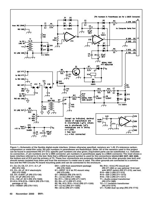
Figure 1—Schematic of the flexible digital-mode interface. Unless otherwise specified, resistors are 1 /4-W, 5%-tolerance carboncomposition<br />
or metal-film units. RS part numbers in parentheses are RadioShack. (Note: All of the resistors used in this project<br />
can be found in assortment RS 271-312; specific part numbers are also given.) Equivalent parts can be substituted; n.c. indicates<br />
no connection. J1 pin numbers are for a DB9 connector; pin numbers in parentheses apply to a DB25 connector. The inset shows a<br />
basic interface referred to in the text. Note that a different ground symbol is used for the connections labeled MIC HOT, MIC GND,<br />
the bottom end of R10 and the primary of T2. These four connections are purposely isolated from the other grounds (see text) and<br />
should remain isolated from them and from the enclosure if a metal one is used. The other grounds are connected to a common<br />
bus and the FAR Circuits PC-board mounting pads and can be connected to the enclosure.<br />
C1, C2, C4, C6, C7, C11—0.1 µF<br />
(RS 272-135)<br />
C3, C5—22 µF, 35 V electrolytic<br />
(RS 272-1026)<br />
C8, C9—0.0047 µF (RS 272-130)<br />
C10—47 pF (RS 272-121)<br />
C12—100 µF, 35 V (RS 272-1028)<br />
D1-D14, D16-D19—1N914 (RS 276-1122,<br />
package of 10)<br />
D15—1N4001 (RS 276-1101)<br />
40 <strong>November</strong> <strong>2000</strong><br />
DS1—LED from assortment package<br />
(RS 276-1622)<br />
K1—DPDT 12-V dc PC-mount relay<br />
(RS 275-249)<br />
Q1—2N2222 (RS 276-1617)<br />
R1—3.3 kΩ (RS 271-1328)<br />
R2, R11—100 kΩ (RS 271-1347)<br />
R3, R4—47 Ω (RS 271-312)<br />
R5, R6, R13, R15—10 kΩ (RS 271-1335)<br />
R7—2.2 kΩ (RS 271-1325)<br />
R8—22 kΩ (RS 271-1339)<br />
R9, R12—10-kΩ PC-mount pot<br />
(RS 271-282) or use optional 10-kΩ pot<br />
with SPDT switch (RS 271-215); see text.<br />
R10—560 Ω (RS 271-312)<br />
R14—220 Ω (RS 271-1313)<br />
R16—100 Ω (RS 271-1311)<br />
T1—Audio-output transformer<br />
(RS 273-1380)<br />
T2—1:1 isolation transformer<br />
(RS 273-1374)<br />
U1—TL082 dual op amp (RS 276-1715)