
Create successful ePaper yourself
Turn your PDF publications into a flip-book with our unique Google optimized e-Paper software.
3D-28 FRONT SUSPENSION<br />
11) Apply grease to spindle bushing inside surface, flange and<br />
shaft (for 4WD) of wheel spindle.<br />
“A”: Grease 99000-25010<br />
CAUTION:<br />
As this hole is a part of the passage of the vacuum<br />
that activates the air locking hub, if it is clogged with<br />
grease, the air locking hub cannot be locked or unlocked.<br />
Therefore, be careful not to apply too much grease<br />
to avoid clogging the vacuum passage.<br />
12) Install wheel spindle to knuckle, coat their mating surface with<br />
sealant.<br />
“B”: Sealant 99000-31110 or 99000-31090<br />
1. Wheel spindle<br />
2. Spindle bushing<br />
13) Install wheel spindle and disc dust cover to steering knuckle.<br />
Tighten wheel spindle bolts to specified torque.<br />
Tightening Torque<br />
(a): 50 N·m (5.0 kg-m, 36.5 lb-ft)<br />
1. Wheel spindle<br />
2. Disc dust cover<br />
14) Blow air into pipes at the top and the front of wheel spindle and<br />
check that it comes out of the hole as shown in figure (for<br />
4WD).<br />
CAUTION:<br />
As this hole is a part of the passage of the vacuum<br />
that activates the air locking hub, if it is clogged with<br />
grease, the air locking hub cannot be locked or unlocked.<br />
Therefore, be careful not to apply too much grease<br />
to avoid clogging the vacuum passage.<br />
15) Connect spindle vacuum hoses to wheel spindle (for 4WD).<br />
16) Connect tie rod and drag rod to steering knuckle, refer to TIE<br />
ROD AND DRAG ROD INSTALLATION of Section 3B.<br />
17) Install wheel hub assembly, refer to steps 5) to 16’) of WHEEL<br />
HUB INSTALLATION in this section.<br />
18) Install wheel and tighten wheel nuts to specified torque, refer<br />
to TIGHTENING TORQUE SPECIFICATIONS in this section.<br />
19) Lower hoist.
PROPELLER SHAFTS 4B-1<br />
SECTION 4B<br />
PROPELLER SHAFTS<br />
NOTE:<br />
All propeller shaft fasteners are an important attaching part in that it could affect the performance of vital<br />
parts and systems, and/or could result in major repair expense. They must be replaced with one of the<br />
same part number or with an equivalent part if replacement becomes necessary. Do not use a replacement<br />
part of lesser quality or substitute design. Torque values must be used as specified during reassembly<br />
to assure proper retention of this part.<br />
Never attempt to heat, quench or straighten any propeller shaft part. Replace it with a new part, or damage<br />
to the part may result.<br />
CONTENTS<br />
4B<br />
GENERAL DESCRIPTION . . . . . . . . . . . . . . . . . . . . . . . . . . . . . . . . . . . . . . . . . . . . . . . . . . . . . . . . . . . . . . . . . . . . . . . . . 4B-1<br />
DIAGNOSIS . . . . . . . . . . . . . . . . . . . . . . . . . . . . . . . . . . . . . . . . . . . . . . . . . . . . . . . . . . . . . . . . . . . . . . . . . . . . . . . . . . . . . . 4B-2<br />
Diagnosis Table . . . . . . . . . . . . . . . . . . . . . . . . . . . . . . . . . . . . . . . . . . . . . . . . . . . . . . . . . . . . . . . . . . . . . . . . . . . . . . . . . 4B-2<br />
Propeller Shaft Joint Check . . . . . . . . . . . . . . . . . . . . . . . . . . . . . . . . . . . . . . . . . . . . . . . . . . . . . . . . . . . . . . . . . . . . . . 4B-2<br />
ON-VEHICLE SERVICE . . . . . . . . . . . . . . . . . . . . . . . . . . . . . . . . . . . . . . . . . . . . . . . . . . . . . . . . . . . . . . . . . . . . . . . . . . . 4B-3<br />
Removal . . . . . . . . . . . . . . . . . . . . . . . . . . . . . . . . . . . . . . . . . . . . . . . . . . . . . . . . . . . . . . . . . . . . . . . . . . . . . . . . . . . . . . . 4B-3<br />
Installation . . . . . . . . . . . . . . . . . . . . . . . . . . . . . . . . . . . . . . . . . . . . . . . . . . . . . . . . . . . . . . . . . . . . . . . . . . . . . . . . . . . . . 4B-3<br />
Universal Joint . . . . . . . . . . . . . . . . . . . . . . . . . . . . . . . . . . . . . . . . . . . . . . . . . . . . . . . . . . . . . . . . . . . . . . . . . . . . . . . . . . 4B-4<br />
TIGHTENING TORQUE SPECIFICATION . . . . . . . . . . . . . . . . . . . . . . . . . . . . . . . . . . . . . . . . . . . . . . . . . . . . . . . . . . . . 4B-6<br />
REQUIRED SERVICE MATERIAL . . . . . . . . . . . . . . . . . . . . . . . . . . . . . . . . . . . . . . . . . . . . . . . . . . . . . . . . . . . . . . . . . . 4B-6<br />
SPECIAL TOOL . . . . . . . . . . . . . . . . . . . . . . . . . . . . . . . . . . . . . . . . . . . . . . . . . . . . . . . . . . . . . . . . . . . . . . . . . . . . . . . . . . 4B-6<br />
GENERAL DESCRIPTION<br />
1. Propeller shaft No. 1<br />
2. Propeller shaft No. 2<br />
3. Propeller shaft No. 3<br />
Tightening Torque<br />
(a): 50 N·m (5.0kg-m, 36.5lb-ft)<br />
(b): 33 N·m (3.3kg-m, 24lb-ft)
4B-4 PROPELLER SHAFTS<br />
Grease splines of propeller shaft No. 2 and No. 3.<br />
“A”: Chassis Grease 99000-25030<br />
Match marks are provided on slip-on spline connections of propeller<br />
shaft No. 2 and No. 3. Inserting splined end into spIined<br />
bore without regard to match marks can be a possible cause of<br />
noise or vibration of propeller shaft. Be sure to index marks.<br />
1. Match mark<br />
UNIVERSAL JOINT<br />
DISASSEMBLY<br />
1) Using special tool, remove 4 circlips.<br />
Special tool<br />
(A): 09900-06108<br />
1. Circlip<br />
2) Apply penetrate lubricant between bearing race outer diameter<br />
and shaft yoke bore.<br />
3) Using a set of special tool, push spider bearing race out 3 – 4<br />
mm (0.12 – 0.16 in.) from shaft yoke side face.<br />
Special tool<br />
(B): 09926-48010<br />
Pushed out value of bearing race from shaft yoke side face<br />
“a”: 3 – 4 mm (0.12 – 0.16 in.)<br />
1. Spider bearing race<br />
2. Shaft yoke side face
PROPELLER SHAFTS 4B-5<br />
4) Tapping shaft yoke with a hammer, remove bearing race from<br />
shaft yoke completely.<br />
5) Take out bearing race on the opposite side of shaft yoke in the<br />
same way as shown above.<br />
1. Bearing race<br />
2. Shaft yoke<br />
6) Push out bearing race on flange yoke in the same way as Step<br />
2).<br />
7) Holding bearing race by a vise, tap flange yoke and take out<br />
race.<br />
8) Take out bearing race on the opposite side of flange yoke in the<br />
same way as Step 5) to Step 6).<br />
1. Flange yoke<br />
2. Bearing race<br />
3. Vise<br />
REASSEMBLY<br />
CAUTION:<br />
Do not reuse spider, bearings and circlips. Otherwise it<br />
may damage propeller shaft or cause abnormal vibration<br />
or noise.<br />
1. Spider<br />
2. Bearing<br />
1) Apply grease to rollers in bearing races.<br />
“A”: Grease 99000-25030<br />
NOTE:<br />
Make sure that rollers in bearing race are all in place.<br />
1. Bearing roller<br />
2. Bearing race<br />
2) With spider inserted into bearing race to prevent rollers in race<br />
from coming out, insert bearing race into shaft yoke until it is<br />
flush with side face of shaft yoke, tapping it by a copper hammer.<br />
1. Copper hammer<br />
2. Bearing race<br />
3. Shaft yoke<br />
4. Spider
4B-6 PROPELLER SHAFTS<br />
3) Insert bearing race into opposite side of shaft yoke until it is flush<br />
with side face of shaft yoke, tapping it by a copper hammer.<br />
4) In the same way as Step 2) to Step 3), insert bearing races into<br />
flange yoke.<br />
5) Using round bar of 22 – 24 mm (0.87 in. – 0.94 in.) in diameter<br />
and hammer, tap bearing races into shaft or flange yoke until circlips<br />
can be installed in its groove on yoke bores.<br />
6) Install 4 circlips in each groove on shaft and flange yoke bores.<br />
NOTE:<br />
After reassembly, ensure that both shaft yoke and flange<br />
yoke move smoothly.<br />
Make sure that each circlip is fitted in groove securely.<br />
TIGHTENING TORQUE SPECIFICATION<br />
Fastener<br />
Tightening torque<br />
N·m kg-m lb-ft<br />
Propeller shaft bolt (propeller shaft No.1 No.2 and No.3 rear<br />
differential side)<br />
50 5.0 36.5<br />
Propeller shaft bolt (propeller shaft No.3 transfer case side) 33 3.3 24<br />
REQUIRED SERVICE MATERIAL<br />
MATERIAL<br />
Lithium grease<br />
RECOMMENDED<br />
SUZUKI PRODUCT<br />
SUPER GREASE C<br />
(99000-25030)<br />
USE<br />
To apply to spider bearing race.<br />
SPECIAL TOOL<br />
09900-06108<br />
Snap ring pliers (Closing type)<br />
09926-48010<br />
Universal joint disassembling<br />
tool set
ENGINE MECHANICAL 6A-49<br />
INSPECTION<br />
Cylinders<br />
Inspect cylinder walls for scratches, roughness, or ridges which<br />
indicate excessive wear. If cylinder bore is very rough or deeply<br />
scratched, or ridged, rebore cylinder and use oversize piston.<br />
Using a cylinder gauge, measure cylinder bore in thrust and axial<br />
directions at two positions as shown in figure.<br />
If any of following conditions is noted, rebore cylinder.<br />
1) Cylinder bore dia. exceeds limit.<br />
2) Difference of measurements at two positions exceeds taper<br />
limit.<br />
3) Difference between thrust and axial measurements exceeds<br />
out-of-round limit.<br />
1. 50 mm (1.96 in.)<br />
2. 95 mm (3.74 in.)<br />
Cylinder bore dia. limit: 74.15 mm (2.9193 in.)<br />
Taper and out-of-round limit: 0.10 mm (0.0039 in.)<br />
NOTE:<br />
If any one of four cylinders has to be rebored, rebore all<br />
four to the same next oversize. This is necessary for the<br />
sake of uniformity and balance.<br />
Pistons<br />
Inspect piston for faults, cracks or other damaged.<br />
Damaged or faulty piston should be replaced.<br />
Piston diameter:<br />
As indicated in figure, piston diameter should be measured at a<br />
position 23 mm (0.91 in.) from piston skirt end in the direction<br />
perpendicular to piston pin.<br />
Piston<br />
diameter<br />
Standard<br />
Oversize:<br />
0.25 mm<br />
(0.0098 in.)<br />
0.50 mm<br />
(0.0196 in.)<br />
73.970 – 73.990 mm<br />
(2.9122 – 2.9130 in.)<br />
74.220 – 74.230 mm<br />
(2.9220 – 2.9224 in.)<br />
74.470 – 74.480 mm<br />
(2.9319 – 2.9323 in.)<br />
1. 23 mm (0.91 in.)
7A-6 MANUAL TRANSMISSION<br />
4) Hoist vehicle and drain transmission oil.<br />
5) Remove exhaust No.1 pipe, refer to Section 6K.<br />
6) Remove propeller shaft No.1 (and No.2, if equipped for 4WD),<br />
refer to Section 4B.<br />
7) Remove gear shift control joint bolt and extension rod bolt.<br />
8) Apply transmission jack and remove rear mounting bracket with<br />
gear shift case mounting bracket and engine rear mounting.<br />
9) Remove rear gear shift control assembly.<br />
1. Gear shift control joint<br />
2. Extension rod<br />
3. Rear mounting bracket<br />
4. Gear shift case mounting bracket<br />
5. Engine rear mounting<br />
6. Rear gear shift control assembly<br />
1. Gear shift knob<br />
2. Gear shift lever<br />
3. Gear shift lever boot<br />
ass’y<br />
4. Gear shift lever boot No.2<br />
5. Gear shift lever boot No.3<br />
6. Gear shift lever boot cover<br />
7. Gear shift lever plate<br />
8. Gear shift control lower<br />
seat bolt<br />
9. Gear control select bolt<br />
10. Gear shift lever case<br />
11. Gear shift rear shaft<br />
12. Extension rod<br />
13. Rear mounting bracket<br />
14. Gear shift case<br />
mounting bracket<br />
15. Engine rear mounting<br />
16. Oil seal<br />
17. Boot<br />
18. Gear shift rear arm<br />
bolt<br />
INSPECTION<br />
Check that gear shift control lever moves smoothly without abnormal<br />
noise.<br />
Check bushes and boot for damage and deterioration.<br />
INSTALLATION<br />
Install in reverse order of removal procedure noting following<br />
points.<br />
“A”: Grease 99000-25010<br />
“B”: Sealant 99000-31110<br />
“C”: Thread lock 99000-32020<br />
Press fit oil seal, referring to figure for installing direction.<br />
Make breather of boot face downward as shown in figure.<br />
Torque bolts to specifications, as given below.<br />
Tightening Torque<br />
(a): 23 N·m (2.3 kg-m, 17.0 lb-ft)<br />
(b): 25 N·m (2.5 kg-m, 18.0 lb-ft)<br />
(c): 18 N·m (1.8 kg-m, 13.0 lb-ft)<br />
(d): 50 N·m (5.0 kg-m, 36.5 lb-ft)<br />
(e): 5.5 N·m (0.55 kg-m, 4.0 lb-ft)<br />
(f): 18 N·m (1.8 kg-m, 13.0 lb-ft) (For 6 mm bolt)<br />
34 N·m (3.4 kg-m, 24.5 lb-ft) (For 8 mm bolt)<br />
NOTE:<br />
Do not reuse for gear shift rear arm bolt whose size is 6 mm.<br />
When installing propeller shaft(s), refer to Section 4B.<br />
When installing exhaust No.1 pipe, refer to Section 6K.<br />
After connect clutch cable, adjust clutch pedal free travel, refer<br />
to Section 7C.
AUTOMATIC TRANSMISSION (4 A/T) 7B-1<br />
SECTION 7B<br />
AUTOMATIC TRANSMISSION (4 A/T)<br />
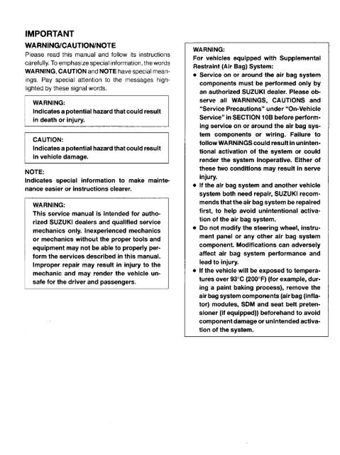
WARNING:<br />
For vehicles equipped with Supplemental Restraint (Air Bag) System<br />
<strong>Service</strong> on and around the air bag system components or wiring must be performed only by an<br />
authorized SUZUKI dealer. Refer to “Air Bag System Components and Wiring Location View” under<br />
“General Description” in air bag system section in order to confirm whether you are performing<br />
service on or near the air bag system components or wiring. Please observe all WARNINGS<br />
and “<strong>Service</strong> Precautions” under “On-Vehicle <strong>Service</strong>” in air bag system section before performing<br />
service on or around the air bag system components or wiring. Failure to follow WARNINGS<br />
could result in unintentional activation of the system or could render the system inoperative. Either<br />
of these two conditions may result in severe injury.<br />
Technical service work must be started at least 90 seconds after the ignition switch is turned to<br />
the “LOCK” position and the negative cable is disconnected from the battery. Otherwise, the system<br />
may be activated by reserve energy in the Sensing and Diagnostic Module (SDM).<br />
NOTE:<br />
The transmission type can only be identified by the vehicle identification number (VIN) because the transmission<br />
external appearances are identical.<br />
However, if the valve body is removed from the transmission case, it can be identified by the fluid drain<br />
holes whether they exist or not.<br />
Type-1: No drain hole exist<br />
Type-2: Drain holes are opened<br />
7B<br />
1. Drain holes<br />
Type-1<br />
On and after JSAFJA33C00100001<br />
On and after JSAFJB33C00100001<br />
On and after JSAFJB33V00100001<br />
On and after JSAFJB33VY0100001<br />
On and after JSAFJB33VY4100001<br />
On and after JS3JB33V 14100001<br />
On and after JS3JB33V Y4100001<br />
On and after JB33V-100001<br />
From JSAFJA43V00100001 to JSAFJA43V00100006<br />
From JSAFJB43V00100001 to JSAFJB43V00118884<br />
From JSAFJB43V00118886 to JSAFJB43V00119017<br />
From JSAFJB43V00109019 to JSAFJB43V00119022<br />
From JSAFJB43V00119024 to JSAFJB43V00119038<br />
From JSAFJB43V24100001 to JSAFJB43V00100117<br />
From JS3JB43V 14100001 to JS3JB43V 14101089<br />
From JS3JB43V 24100001 to JS3JB43V 24100042
7B-2 AUTOMATIC TRANSMISSION (4 A/T)<br />
Type-2<br />
On and after JSAFJA43V00100007<br />
JSAFJB43V00118885<br />
JSAFJB43V00119018<br />
JSAFJB43V00119023<br />
On and after JSAFJB43V00119039<br />
On and after JSAFJB43V20100001<br />
On and after JSAFJB43V24100118<br />
On and after JS3JB43V 14101090<br />
On and after JS3JB43V 24100043<br />
CONTENTS<br />
GENERAL DESCRIPTION . . . . . . . . . . . . . . 7B- 3<br />
ELECTRONIC SHIFT CONTROL<br />
SYSTEM . . . . . . . . . . . . . . . . . . . . . . . . . . 7B- 7<br />
DIAGNOSIS . . . . . . . . . . . . . . . . . . . . . . . . . . . 7B-14<br />
Trouble Diagnosis Table . . . . . . . . . . . . . . 7B-18<br />
Stall Test . . . . . . . . . . . . . . . . . . . . . . . . . . . . 7B-20<br />
Time Lag Test . . . . . . . . . . . . . . . . . . . . . . . 7B-21<br />
Line Pressure Test . . . . . . . . . . . . . . . . . . . 7B-21<br />
Engine Brake Test . . . . . . . . . . . . . . . . . . . 7B-22<br />
“P” Range Test . . . . . . . . . . . . . . . . . . . . . . 7B-23<br />
ELECTRONIC CONTROL SYSTEM<br />
DIAGNOSIS . . . . . . . . . . . . . . . . . . . . . . . . . . 7B-24<br />
Precautions in Diagnosing Troubles . . . . 7B-24<br />
Diagnostic Trouble Code(s) Check . . . . . 7B-25<br />
How to Clear Diagnostic Trouble<br />
Code(s) (DTC) . . . . . . . . . . . . . . . . . . . . . . . . 7B-27<br />
Diagnostic Trouble (DTC) Code Table . . . . . 7B-28<br />
TCM Power and Ground Circuit Check . . . . . 7B-29<br />
DTC 14 Turbine Rev. Sensor Signal . . . . . . . 7B-30<br />
DTC 18 Turbine Rev. Sensor, A/T VSS<br />
or A/T Itself . . . . . . . . . . . . . . . . . . . . . 7B-31<br />
DTC 21 Shift Solenoid No. 1 . . . . . . . . . . . . . . 7B-32<br />
DTC 23 Shift Solenoid No. 2 . . . . . . . . . . . . . . 7B-32<br />
DTC 43 Shift Solenoid No. 3 . . . . . . . . . . . . . . 7B-32<br />
DTC 45 Shift Solenoid No. 4 . . . . . . . . . . . . . . 7B-32<br />
DTC 25 Lock-up Solenoid . . . . . . . . . . . . . . . . 7B-32<br />
DTC 22 Shift Solenoid No. 1 . . . . . . . . . . . . . . 7B-34<br />
DTC 24 Shift Solenoid No. 2 . . . . . . . . . . . . . . 7B-34<br />
DTC 44 Shift Solenoid No. 3 . . . . . . . . . . . . . . 7B-34<br />
DTC 46 Shift Solenoid No. 4 . . . . . . . . . . . . . . 7B-34<br />
DTC 26 Lock-up Solenoid . . . . . . . . . . . . . . . . 7B-34<br />
DTC 31 A/T VSS . . . . . . . . . . . . . . . . . . . . . . . . 7B-35<br />
DTC 32 Throttle Position Signal . . . . . . . . . . . 7B-37<br />
DTC 33 Throttle Position Signal . . . . . . . . . . . 7B-38<br />
DTC 34 Shift Switch . . . . . . . . . . . . . . . . . . . . . 7B-39<br />
DTC 35 Engine Rev. Signal . . . . . . . . . . . . . . 7B-41<br />
DTC 36 A/T Fluid Temperature Sensor . . . . . 7B-42<br />
DTC 52 Power Source Relay in TCM . . . . . . 7B-44<br />
Inspection of TCM and Its Circuits . . . . . . . . . 7B-45<br />
ON-VEHICLE SERVICE . . . . . . . . . . . . . . . . . . . 7B-47<br />
MAINTENANCE SERVICE . . . . . . . . . . . . . . . 7B-47<br />
Fluid Level . . . . . . . . . . . . . . . . . . . . . . . . . . . 7B-47<br />
Fluid Change Intervals . . . . . . . . . . . . . . . . 7B-48<br />
Changing Fluid . . . . . . . . . . . . . . . . . . . . . . . 7B-48<br />
Oil Cooler Hoses . . . . . . . . . . . . . . . . . . . . . 7B-48<br />
SELECTOR LEVER . . . . . . . . . . . . . . . . . . . . . 7B-49<br />
SHIFT SWITCH . . . . . . . . . . . . . . . . . . . . . . . . 7B-50<br />
SELECTOR ROD . . . . . . . . . . . . . . . . . . . . . . . 7B-52<br />
A/T VSS . . . . . . . . . . . . . . . . . . . . . . . . . . . . . . . 7B-53<br />
TURBINE REV. SENSOR . . . . . . . . . . . . . . . . 7B-54<br />
VSS . . . . . . . . . . . . . . . . . . . . . . . . . . . . . . . . . . . 7B-54<br />
THROTTLE POSITION SENSOR . . . . . . . . 7B- 54<br />
ECT SENSOR . . . . . . . . . . . . . . . . . . . . . . . . . 7B- 54<br />
O/D CUT SWITCH . . . . . . . . . . . . . . . . . . . . . 7B- 55<br />
SHIFT SOLENOID VALVES AND LOCK-UP<br />
SOLENOID VALVE . . . . . . . . . . . . . . . . . . . . 7B- 56<br />
A/T FLUID TEMP. SENSOR . . . . . . . . . . . . . 7B- 56<br />
EXTENSION CASE OIL SEAL . . . . . . . . . . . 7B- 57<br />
TCM . . . . . . . . . . . . . . . . . . . . . . . . . . . . . . . . . 7B- 58<br />
Learning Control Memory Initialization . . 7B- 58<br />
INTERLOCK CABLE (if equipped) . . . . . . . 7B- 59<br />
TRANSMISSION UNIT REPAIR<br />
OVERHAUL . . . . . . . . . . . . . . . . . . . . . . . . . . . . 7B- 61<br />
DISMOUNTING . . . . . . . . . . . . . . . . . . . . . . . 7B- 61<br />
REMOUNTING . . . . . . . . . . . . . . . . . . . . . . . . 7B- 62<br />
DISASSEMBLY . . . . . . . . . . . . . . . . . . . . . . . . 7B- 63<br />
DISASSEMBLY OF SUBASSEMBLY . . . . . 7B- 71<br />
Oil Pump . . . . . . . . . . . . . . . . . . . . . . . . . . . 7B- 72<br />
Front Clutch . . . . . . . . . . . . . . . . . . . . . . . . . 7B- 74<br />
Rear Clutch . . . . . . . . . . . . . . . . . . . . . . . . . 7B- 79<br />
Planetary Set . . . . . . . . . . . . . . . . . . . . . . . 7B- 84<br />
Valve Body . . . . . . . . . . . . . . . . . . . . . . . . . 7B- 86<br />
Output Shaft Assembly . . . . . . . . . . . . . . . 7B- 91<br />
UNIT ASSEMBLY . . . . . . . . . . . . . . . . . . . . . . 7B- 92<br />
TIGHTENING TORQUE SPECIFICATIONS . 7B-105<br />
SPECIAL TOOLS . . . . . . . . . . . . . . . . . . . . . . . . 7B-106<br />
REQUIRED SERVICE MATERIALS . . . . . . . . 7B-107
7B-24 AUTOMATIC TRANSMISSION (4 A/T)<br />
ELECTRONIC CONTROL SYSTEM<br />
DIAGNOSIS<br />
TCM has on-board diagnostic system (a system self-diagnosis<br />
function).<br />
Investigate where the trouble is by referring to “DIAGNOSTIC<br />
FLOW TABLE” and ”DIAGNOSTIC TROUBLE CODE TABLE” on<br />
later pages.<br />
PRECAUTIONS IN DIAGNOSING TROUBLES<br />
[PRECAUTIONS IN IDENTIFYING DIAGNOSTIC TROUBLE<br />
CODE]<br />
Before identifying diagnostic trouble code indicated by “O/D<br />
OFF” light, don’t disconnect couplers from TCM, battery cable<br />
from battery, TCM ground wire harness from engine. Such disconnection<br />
will erase memorized trouble in TCM memory.<br />
The DTC stored in the TCM memory is output by flashing of “O/D<br />
OFF” light with the diagnosis switch terminal grounded.<br />
If no DTC is stored in the TCM memory, Code 12 is output repeatedly.<br />
If DTCs are stored in the TCM memory, they are output after<br />
Code 12 output starting from the smallest code number in the increasing<br />
order. After all DTCs are output, Code 12 is output<br />
again and so are DTCs.<br />
When replacing TCM with used one, learning control memory in<br />
TCM should be initialized after the replacement referring to<br />
“LEARNING CONTROL MEMORY INITIALIZATION” in this<br />
section.<br />
1. Data link connector (DLC)<br />
[INTERMITTENT TROUBLES] and [NOTES ON SYSTEM CIR-<br />
CUIT INSPECTION]<br />
Refer to SECTION 0A.
AUTOMATIC TRANSMISSION (4 A/T) 7B-55<br />
O/D cut switch ON<br />
O/D cut switch OFF<br />
1. O/D cut switch<br />
2. Shift lever<br />
O/D CUT SWITCH<br />
INSPECTION<br />
1) Remove console box.<br />
2) Disconnect O/D cut switch coupler.<br />
3) Check continuity between O/D cut switch terminals.<br />
O/D cut switch ON OFF<br />
Continuity Continuity No continuity<br />
SHIFT SOLENOID VALVES AND A/T FLUID<br />
TEMP. SENSOR<br />
REMOVAL<br />
1) Disconnect negative cable from battery.<br />
2) Drain A/T fluid.<br />
3) Remove A/T oil pan.<br />
4) Disconnect A/T fluid temp. sensor coupler.<br />
1. A/T oil pan<br />
5) Remove one of oil strainer bolts and ground wire for shift solenoid<br />
valve No.1.<br />
6) Disconnect shift solenoid and A/T fluid temp. sensor couplers.<br />
7) Remove shift solenoid valves (No.1, No.3 and No.4) and lockup<br />
solenoid valve.<br />
8) Remove valve body ass’y.<br />
9) Remove shift solenoid valve No.2.<br />
1. Valve body ass’y<br />
2. Coupler<br />
3. A/T fluid temp. sensor<br />
4. Oil strainer ass’y<br />
5. Bolt A<br />
6. Bolt B<br />
7. Bolt C<br />
8. Ground wire<br />
9. Oil strainer bolt
7B-56 AUTOMATIC TRANSMISSION (4 A/T)<br />
SHIFT SOLENOID VALVES AND LOCK-UP SOLE-<br />
NOID VALVE<br />
INSPECTION<br />
Resistance Check<br />
Shift solenoid No.1, No.2, No.3, No.4 and lock-up solenoid.<br />
Check resistance between terminal and solenoid body.<br />
Standard resistance: 11.5 – 12.5 <br />
1. Shift solenoid or lock-up solenoid<br />
Operation check<br />
Shift solenoid valves No.1, No.2, No.3, No.4 and lock-up solenoid<br />
When solenoids is connected to the battery as shown in figure,<br />
check that the solenoid actuates with a click sound.<br />
1. Shift solenoid or<br />
lock-up solenoid<br />
2. Battery<br />
A/T FLUID TEMP. SENSOR<br />
INSPECTION<br />
Warm up A/T fluid temp. sensor. Thus make sure its resistance decrease<br />
with the increase of temperature.<br />
1. A/T fluid temperature sensor coupler<br />
Temperature<br />
20C (68F)<br />
40C (104F)<br />
60C (140F)<br />
Resistance<br />
2.5 k<br />
1.2 k<br />
0.6 k<br />
INSTALLATION<br />
Reverse removal procedure for installation noting following points.<br />
Tighten solenoid valve bolts and valve body ass’y bolts to specification<br />
referring to 7B-101.<br />
Tightening Torque for solenoid valve bolts:<br />
8 N·m (0.8 kg-m, 6.0 lb-ft)<br />
Tightening Torque for Valve Body Ass’y Bolts A, B and C:<br />
10 N·m (1.0 kg-m, 7.5 lb-ft)<br />
Make sure that slot of manual valve is fitted to pin of manual<br />
valve lever.
AUTOMATIC TRANSMISSION (4 A/T) 7B-57<br />
Clean mating surface of A/T oil pan and A/T case and install new<br />
gasket to A/T oil pan.<br />
Tighten bolts to specification.<br />
Tightening Torque<br />
(a): 7.5 N·m (0.75 kg-m, 5.5 lb-ft)<br />
1. Magnet<br />
2. Gasket<br />
3. Oil pan<br />
Refill A/T fluid referring to 7B-48 and verify that there is no A/T<br />
fluid leakage.<br />
1. Oil seal<br />
2. Extension case<br />
EXTENSION CASE OIL SEAL<br />
REPLACEMENT<br />
1) Lift up vehicle and drain transmission oil.<br />
2) Remove propeller shaft No.1 and No.2.<br />
Refer to Section 4B for procedure.<br />
3) Remove extension case oil seal by using screwdriver or like.<br />
4) Install new differential side oil seal by using special tool.<br />
NOTE:<br />
For oil seal installation, press-fit oil seal so that transmission<br />
case end face is flush with oil seal end face.<br />
Special Tool<br />
(A): 09913-75520<br />
5) Install propeller shafts referring to Section 4B.<br />
6) Refill A/T fluid referring to p. 7B-69.
7B-58 AUTOMATIC TRANSMISSION (4 A/T)<br />
TRANSMISSION CONTROL MODULE (TCM)<br />
CAUTION:<br />
TCM and ECM consist of highly precise parts, so when<br />
handling it (or them), be careful not to expose to excessive<br />
shock.<br />
REMOVAL<br />
Remove ECM and separate TCM from ECM bracket.<br />
Refer to SECTION 6E for ECM removal.<br />
INSTALLATION<br />
Reverse removal procedure noting the following.<br />
Connect ECM and TCM couplers securely.<br />
If the vehicle is equipped with air bag system, be sure to enable<br />
air bag system after TCM and ECM are back in place. Refer to<br />
“Enabling Air Bag System” in Section 10B.<br />
LEARNING CONTROL MEMORY INITIALIZATION<br />
Initialization of learning control memory in TCM should be made<br />
upon replacement of parts as explained below.<br />
Automatic transmission assembly replacement with new or<br />
used one<br />
Any A/T brake component parts replacement such as discs,<br />
plates and flange with new or used one(s)<br />
Any A/T clutch component parts replacement such as discs,<br />
plates and flange with new or used one(s)<br />
Replacement of TCM with used one<br />
1) Turn ignition switch to “ON” position. (Do not start engine.)<br />
2) Bring diag. switch terminal of monitor coupler in contact with<br />
ground terminal using service wire.<br />
3) Repeat shifting selector lever from “D” to “2” position and vice<br />
versa for 3 times within 10 seconds to complete memory initialization.<br />
4) Confirm initialization by DTC set in system referring to “DTC<br />
CHECK” in this section.<br />
DTC No.12: completion of initialization is confirmed<br />
DTC No.52: initialization is failed<br />
5) If you failed initialization, repeat steps 1) to 3).<br />
NOTE:<br />
“O/D OFF” lamp continues to turn on while initialization.<br />
DTCs which might have been set in system other than No.12<br />
and 52 are also erased by initialization.<br />
1. Monitor coupler<br />
2. Diag. switch terminal<br />
3. Ground terminal
AUTOMATIC TRANSMISSION (4 A/T) 7B-61<br />
TRANSMISSION UNIT REPAIR OVERHAUL<br />
NOTE:<br />
When transmission is replaced, or when any A/T clutch or brake component parts such as discs, plates<br />
and flange are replaced with new or used one(s), learning control memory of TCM should be initialized after<br />
those replacement referring to “LEARNING CONTROL MEMORY INITIALIZATION” in this section.<br />
DISMOUNTING<br />
NOTE:<br />
If automatic transmission is overhauled later on, draining A/T fluid at this point will facilitate work.<br />
1) Remove following parts.<br />
Propeller shafts No.1 and No.2 (refer to SECTION 4B)<br />
Exhaust pipe (refer to SECTION 6K)<br />
Negative cable from battery<br />
2) Disconnect couplers. (2 couplers from wire harness and 1<br />
from shift switch)<br />
3) Remove selector rod from shift control shaft lever by removing<br />
pin.<br />
4) Remove oil cooler hoses from pipes.<br />
1. Selector rod<br />
2. Shift control<br />
shaft lever<br />
3. Pin<br />
NOTE:<br />
To avoid leakage of transmission fluid, plug open ends of<br />
oil cooler pipes and hoses right after they are disconnected.<br />
5) Remove torque converter housing lower plate.<br />
6) Remove drive plate bolts.<br />
To lock drive plate, engage a flat screwdriver with drive plate<br />
gear.<br />
7) Remove starting motor.<br />
1. Flat screwdriver<br />
2. Wrench<br />
8) With transmission held up on jack, remove engine to transmission<br />
bolts and nuts.<br />
9) Remove transmission rear mounting bracket.<br />
10) Move transmission to the rear a little and lower it including<br />
torque converter.<br />
1. Rear mounting bracket<br />
WARNING:<br />
Be sure to keep transmission horizontal throughout<br />
the work. Should it be tilted, torque converter may<br />
fall off and cause personal injury and A/T fluid may<br />
flow out.
7B-64 AUTOMATIC TRANSMISSION (4 A/T)<br />
4) Remove one of oil strainer bolts and ground wire of shift solenoid<br />
valve No.1.<br />
Disconnect couplers from solenoid valves, and A/T fluid temperature<br />
sensor.<br />
Remove A/T fluid temperature sensor and oil strainer assembly.<br />
5) Remove valve body assembly.<br />
CAUTION:<br />
Be careful not to let manual valve fall off when removing<br />
valve body assembly.<br />
NOTE:<br />
There are three kinds of bolts fixing valve body ass’y.<br />
1. Valve body ass’y<br />
2. Coupler<br />
3. A/T fluid temp. sensor<br />
4. Oil strainer ass’y<br />
5. Bolt A<br />
6. Bolt B<br />
7. Bolt C<br />
8. Ground wire<br />
9. Oil strainer bolt<br />
6) Remove solenoid harness assembly.<br />
7) Remove accumulator pistons and springs.<br />
To remove C1, C2 and B1 accumulator pistons and springs,<br />
position a rag on pistons to catch each piston.<br />
To remove pistons, force low-pressure compressed air (1 kg/<br />
cm 2 , 15 psi, 100 kPa, max) into hole as shown in figure, and pop<br />
each piston into the rag.<br />
To remove B0 accumulator piston and spring, remove snap ring<br />
and accumulator spacer, then remove spring and piston.<br />
NOTE:<br />
Do not push accumulator pistons with fingers or anything<br />
before removing them. Pushing them may cause compressed<br />
fluid in accumulator to spew out of hole and get to<br />
your face and clothes.<br />
1. C1 accumulator piston<br />
2. C2 accumulator piston<br />
3. B1 accumulator piston<br />
4. Hole
AUTOMATIC TRANSMISSION (4 A/T) 7B-79<br />
REAR CLUTCH (C2 CLUTCH)<br />
1. Input shaft oil seal ring<br />
2. Input shaft subassembly<br />
3. D-ring<br />
4. Rear clutch piston<br />
5. Rear clutch return spring seat<br />
6. Rear clutch balancer<br />
7. Shaft snap ring<br />
8. Clutch plate<br />
9. Clutch disc<br />
10. Clutch flange<br />
11. Snap ring<br />
12. Clutch flange (Type-1) or Clutch<br />
plate (Type-2) See NOTE.<br />
NOTE:<br />
Identify transmission type by VIN listed on<br />
the first page of this section.<br />
DISASSEMBLY<br />
1) Remove snap ring.<br />
2) Remove flange, discs and plates.<br />
1. Flange<br />
3) Remove shaft snap ring.<br />
Compress piston return springs and remove shaft snap ring.<br />
Place special tool (clutch spring compressor) on spring seat<br />
and compress spring with a press, and then remove shaft snap<br />
ring, using a screwdriver.<br />
1. Spring seat snap ring<br />
2. Press<br />
3. Screwdriver<br />
CAUTION:<br />
Do not push down return spring more than necessary.<br />
Special Tool<br />
(A): 09926-96020
AUTOMATIC TRANSMISSION (4 A/T) 7B-81<br />
ASSEMBLY<br />
1) Install new D-ring and oil seals to input shaft subass’y.<br />
Apply grease to D-ring and fit it to input shaft subass’y.<br />
Grease 99000-25030<br />
2) Install piston into input shaft subass’y.<br />
Apply grease to the lip of the piston.<br />
1. Input shaft subass’y<br />
2. Oil seal<br />
Grease 99000-25030<br />
Use care that the lip does not get twisted or caught.<br />
3) Install rear clutch return spring seat and rear clutch balancer.<br />
3. Snap ring<br />
4. Rear clutch balancer<br />
5. Rear clutch return spring seat<br />
6. Rear clutch piston<br />
7. Input shaft subass’y<br />
1. Snap ring<br />
2. Press<br />
3. Screwdriver<br />
4) Install shaft snap ring.<br />
Compress return springs and install shaft snap rings in groove<br />
by using a screwdriver.<br />
Place special tool (clutch spring compressor) on spring seat<br />
and compress springs with a press.<br />
CAUTION:<br />
Do not compress return spring more than necessary.<br />
Special Tool<br />
(A): 09926-96020<br />
5) Install discs, plates and flanges in following order.<br />
Flange (Type-1) or Plate (Type-2) Disc Plate <br />
Disc Plate Disc Plate Disc Plate <br />
Disc Plate Disc Flange<br />
1. Flange<br />
NOTE:<br />
Before assembly, new discs should be soaked in automatic<br />
transmission fluid for at least 2 hours.<br />
Identify transmission type by VIN listed on the first page<br />
of this section.
7B-92 AUTOMATIC TRANSMISSION (4 A/T)<br />
UNIT ASSEMBLY<br />
CAUTION:<br />
Automatic transmission consists of highly precise parts. As even a flaw in a small part may cause<br />
oil leakage or decrease in function, check each part carefully before installation.<br />
Clean all parts with compressed air. Never use wiping cloths or rags.<br />
Before assembling new clutch discs and brake discs, soak them in automatic transmission fluid<br />
for at least 2 hours.<br />
Be sure to use new gaskets and O-rings.<br />
Lubricate O-rings with automatic transmission fluid.<br />
Apply automatic transmission fluid on sliding or rotating surfaces of the parts before assembly.<br />
Use yellow petrolatum grease or Suzuki Super Grease C to retain parts in place.<br />
Be sure to install thrust bearings and races in correct direction and position.<br />
Make sure that snap ring ends are not aligned with one of cutouts and are installed in groove correctly.<br />
Do not use adhesive cements on gaskets and similar parts.<br />
Be sure to torque each bolt and nut to specification.<br />
1) Install new O-rings (inside and outside) to B2 brake piston, and<br />
apply grease to them.<br />
Grease : 99000-25030<br />
2) [In the case of transmission type-1]<br />
Install B2 brake piston to transmission case.<br />
[In the case of transmission type-2]<br />
Install B2 brake piston with two fingers, which have mounded<br />
part between them, aligned with transmission case hole as<br />
shown in figure.<br />
NOTE:<br />
Identify transmission type by VIN listed on the first page of<br />
this section.<br />
3) Install B1 brake piston and B1 & B2 return spring assembly to<br />
transmission case.<br />
4) Install snap ring by compressing return spring ass’y thru B2<br />
brake piston seat with hydraulic press and special tool.<br />
NOTE:<br />
Don’t compress B1 & B2 return spring ass’y more than necessary<br />
or it may get damaged.<br />
Special Tool<br />
(A): 09926-96010<br />
1. Snap ring<br />
2. B1 & B2 return spring<br />
ass’y<br />
3. B1 brake piston<br />
4. B2 brake piston<br />
5. O-ring<br />
6. Hydraulic press<br />
7. Mounded part of B2<br />
brake piston<br />
8. Hole of transmission<br />
case
AUTOMATIC TRANSMISSION (4 A/T) 7B-93<br />
5) Install B1 brake discs, plates and flange to B2 brake piston in<br />
following order.<br />
Plate Disc Plate Disc Plate Disc <br />
Plate Disc Plate Disc Flange<br />
6) [In the case of transmission type-1]<br />
Install snap ring to B2 brake piston.<br />
[In the case of transmission type-2]<br />
Install snap ring to B2 brake piston with antirotation protrusion<br />
aligned with gap between two fingers having mounded part.<br />
1. Snap ring<br />
2. B2 brake piston<br />
3. Antirotation protrusion<br />
7) Measure B1 brake stroke and clearance in following manner.<br />
B1 Brake Stroke:<br />
Set the dial gauge to 1st & 2nd brake (B1 brake) piston through<br />
B1 brake spring seat hole as shown. Blow compressed air into<br />
hole shown in figure. Then measure the difference as the compressed<br />
air is blown in.<br />
Standard Value for B1 Brake Stroke : 1.75 – 2.00 mm<br />
(0.0689 – 0.0787 in.)<br />
B1 Brake Clearance:<br />
Blow compressed air into the hole shown in figure.<br />
Measure the difference.<br />
Standard Value for B1 Brake Clearance: 1.30 – 2.00 mm<br />
(0.0512 – 0.0787 in.)<br />
If the measured value(s) is (are) out of specification, select the<br />
flange from table below and repeat this step until the measured<br />
values are within specification.<br />
Available Flange Size<br />
(thickness)<br />
2.875 mm (0.113 in.)<br />
3.050 mm (0.120 in.)<br />
3.225 mm (0.127 in.)<br />
3.400 mm (0.134 in.)<br />
3.575 mm (0.141 in.)<br />
1. Dial gauge<br />
2. B1 brake spring seat<br />
3. Tip of dial gauge<br />
4. B1 brake piston<br />
5. Brake flange<br />
6. Air gun<br />
7. Transmission case
7B-94 AUTOMATIC TRANSMISSION (4 A/T)<br />
1. Cushion plate<br />
2. Front<br />
3. Rear<br />
8) Install B2 brake discs, plates and flange in following order.<br />
Plate Cushion plate Plate Disc Plate<br />
(thick) Disc Plate (thick) Disc Flange<br />
NOTE:<br />
Cushion plate has installing direction as shown in figure.<br />
9) Hold above parts with snap ring.<br />
10) Measure B2 brake stroke and clearance in following manner.<br />
B2 Brake Stroke:<br />
Set the dial gauge to reverse brake (B2 brake) piston through<br />
B1 brake spring seat hole as shown. Blow compressed air into<br />
hole shown in figure. Then measure the difference as the compressed<br />
air is blown in.<br />
Standard Value for B2 Brake Stroke : 2.22 – 2.47 mm<br />
(0.0874 – 0.0972 in.)<br />
B2 Brake Clearance:<br />
Blow compressed air into the hole shown in figure.<br />
Measure the difference.<br />
Standard Value for B2 Brake Clearance: 0.60 – 1.70 mm<br />
(0.0236 – 0.0669 in.)<br />
If the measured value(s) is (are) out of specification, select the<br />
flange from table below and repeat this step until the measured<br />
values are within specification.<br />
Available Flange Size<br />
(thickness)<br />
2.36 mm (0.093 in.)<br />
2.54 mm (0.100 in.)<br />
2.72 mm (0.107 in.)<br />
2.90 mm (0.114 in.)<br />
1. Dial gauge<br />
2. B1 brake spring seat<br />
3. Tip of dial gauge<br />
4. B1 brake piston<br />
5. Brake flange<br />
6. Air gun<br />
7. Transmission case
AUTOMATIC TRANSMISSION (4 A/T) 7B-95<br />
11) Install thrust needle roller bearing and rear sun gear. Turn rear<br />
sun gear right and left to match the brake discs and the spline<br />
of rear sun gear.<br />
12) Install thrust needle roller bearing and planetary set. Turn<br />
planetary set right and left to match the gears of the rear sun<br />
gear and the gears of the planetary set.<br />
1. Planetary set<br />
2. Thrust needle roller bearing<br />
3. Rear sun gear<br />
13) Install new inner and outer O-rings to B0 brake piston and apply<br />
grease to them.<br />
“A”: Grease 99000-25030<br />
Install brake piston to B0 brake drum.<br />
14) Install B0 brake piston & drum ass’y to transmission case, in<br />
such way that the edge A comes at the position as shown in<br />
figure. Make sure that the O-rings are not twisted or caught.<br />
15) Place B0 brake piston return spring subass’y on piston. Make<br />
sure that each spring fits the holes on the piston.<br />
16) Push down return spring subass’y and install snap ring.<br />
CAUTION:<br />
Check that the opening of snap ring does not face the<br />
cored-hole of the transmission case.<br />
1. Snap ring<br />
2. B0 brake piston return spring subass’y<br />
3. B0 brake piston<br />
4. O-ring (outer)<br />
5. Cored-hole
7B-96 AUTOMATIC TRANSMISSION (4 A/T)<br />
17) Install B0 brake discs, plates and flange in following order.<br />
Plate Disc Plate Disc Flange<br />
NOTE:<br />
The flat surface of B0 flange must face to B0 disc.<br />
Clearance<br />
18) Inspect B0 brake piston stroke and clearance by blowing compressed<br />
air into hole shown in figure.<br />
Make sure that the obtained piston stroke and clearance satisfy<br />
the standard value.<br />
To Measure Clearance:<br />
Set dial gauge to the top of B0 brake flange and blow compressed<br />
air into the hole shown in figure.<br />
To Measure Piston Stroke:<br />
Piston Stroke<br />
Set dial gauge to the step of B0 brake piston as shown in figure.<br />
Blow compressed air into the hole shown in figure and<br />
measure the value for piston stroke.<br />
Standard Values for<br />
Clearance : 0.50 – 1.05 mm (0.0197 – 0.0<strong>413</strong> in.)<br />
Piston stroke : 0.70 – 1.05 mm (0.0275 – 0.0<strong>413</strong> in.)<br />
If the measured value(s) is (are) out of specification, select the<br />
flange from table below and repeat this step until the measured<br />
values are within specification.<br />
Available Flange Size<br />
(thickness)<br />
2.35 mm (0.093 in.)<br />
2.60 mm (0.102 in.)<br />
2.85 mm (0.112 in.)<br />
3.10 mm (0.122 in.)<br />
1. Dial gauge<br />
2. Tip of dial gauge<br />
3. Air gun<br />
4. Blow compressed air into this hole<br />
19) Install front sun gear to planetary set.<br />
1. Needle roller<br />
bearing<br />
2. Front sun gear
AUTOMATIC TRANSMISSION (4 A/T) 7B-97<br />
20) Install thrust needle roller bearing to intermediate shaft.<br />
1. Thrust needle roller bearing<br />
2. Intermediate shaft<br />
21) Install intermediate shaft to transmission case.<br />
1. Intermediate shaft<br />
22) Install rear disc clutch assembly by turning it right and left to<br />
match the clutch disc of rear disc clutch ass’y and the spline<br />
of intermediate shaft.<br />
1. Rear disc clutch ass’y<br />
23) Install thrust bearing race and thrust needle roller bearing.<br />
“A”: Grease 99000-25030<br />
1. Thrust bearing race<br />
2. Thrust needle roller bearing<br />
24) Install front disc clutch assembly by turning it right and left to<br />
match the clutch disc of front disc clutch ass’y and the spline<br />
of follow shaft.<br />
1. Front disc clutch assembly<br />
2. Transmission case
7B-98 AUTOMATIC TRANSMISSION (4 A/T)<br />
25) Install gasket to transmission case and install oil pump assembly<br />
to transmission case.<br />
Tightening Torque:<br />
(a): 12 N·m (1.2 kg-m, 8.5 lb-ft)<br />
1. Oil pump<br />
26) Measure input shaft end play.<br />
Set dial gauge as shown in figure and measure the play of the<br />
input shaft.<br />
Standard Value of Input Shaft End Play: 0.3 – 0.9 mm<br />
(0.012 – 0.036 in.)<br />
If the obtained value is out of standard value, select thrust<br />
bearing race (installed in step 22) of different thickness shown<br />
in table below and adjust the play.<br />
Available Thrust Bearing<br />
Race Size (thickness)<br />
1.3 mm (0.051 in.)<br />
1.7 mm (0.067 in.)<br />
2.1 mm (0.083 in.)<br />
1. Dial gauge<br />
2. Input shaft end<br />
3. Oil pump<br />
27) Apply grease to oil pump D-ring.<br />
Install new gasket to transmission case and install torque converter<br />
housing.<br />
Tightening Torque:<br />
(a): 19 N·m (1.9 kg-m, 14.0 lb-ft)<br />
Grease: 99000-25030<br />
1. Torque converter housing<br />
NOTE:<br />
Use new bolts.<br />
28) Apply grease to lip of new oil seal and drive in oil seal till it contacts<br />
with transmission case.<br />
29) After installing new sleeve cover and washers to manual shift<br />
lever, install manual shift shaft and manual shift lever to transmission<br />
case.<br />
1. Oil seal<br />
2. Sleeve cover<br />
3. <strong>Manual</strong> shift lever<br />
4. <strong>Manual</strong> shift shaft<br />
5. Washer
AUTOMATIC TRANSMISSION (4 A/T) 7B-99<br />
30) Align hole in manual shift shaft with that in manual shift lever<br />
and drive in new manual shift lever pin through sleeve cover.<br />
1. Pin punch<br />
31) Turn sleeve cover by 90 and caulk securely with pin punch.<br />
Then check that manual shift shaft turns smoothly.<br />
1. Detent spring<br />
2. Parking rod<br />
32) Install detent spring and parking rod as shown in figure.<br />
Tightening Torque<br />
(a): 15N·m (1.5 kg-m, 11.0 Ib-ft)<br />
33) Install parking pawl, spring and parking pawl shaft as shown<br />
in figure.<br />
1. Parking pawl shaft<br />
2. Spring<br />
3. Parking pawl
7B-100 AUTOMATIC TRANSMISSION (4 A/T)<br />
34) Install O-rings to each accumulator piston and apply grease or<br />
ATF to them.<br />
“A”: Grease 99000-25030<br />
35) Install B0 accumulator piston, compression spring gray paint<br />
and accumulator spacer.<br />
Hold them with snap ring.<br />
NOTE:<br />
Make sure that the snap ring is fitted to the groove of<br />
B1-B0 accumulator cylinder.<br />
Make sure that the O-ring is not twisted or caught when<br />
installing.<br />
36) Install B1 accumulator spring (with light blue paint) and accumulator<br />
piston.<br />
NOTE:<br />
Make sure that the O-ring is not twisted or caught when<br />
installing.<br />
1. C2 accumulator piston (large)<br />
2. O-ring<br />
3. C2 accumulator spring (with pink paint)<br />
4. B1 accumulator piston (with 1 groove)<br />
5. B1 accumulator spring (with light blue paint)<br />
6. Snap ring<br />
7. Accumulator spacer<br />
8. B0 accumulator spring (with white paint)<br />
9. B0 accumulator piston<br />
10. C1 accumulator piston (with 2 grooves)<br />
11. C1 accumulator spring<br />
12. C2 accumulator spring (with orange paint)<br />
13. C2 accumulator piston (small)<br />
37) Install wire-to-solenoid assembly.<br />
Fix it with sleeve lock plate and a bolt.<br />
1. Wire-to-solenoid ass’y<br />
2. Sleeve lock plate<br />
NOTE:<br />
Apply grease to O-ring of wire-to-solenoid ass’y.<br />
Match the arrow mark on wire-to-solenoid ass’y with the<br />
sleeve lock plate.<br />
Tightening Torque:<br />
(a): 8.0 N·m (0.8 kg-m, 6.0 Ib-ft)<br />
Grease 99000-25030
AUTOMATIC TRANSMISSION (4 A/T) 7B-101<br />
38) Install valve body to transmission case.<br />
First match the pin of the manual valve lever to the slot of the<br />
manual valve.<br />
NOTE:<br />
Connect shift solenoid No.2 coupler (green) before tightening<br />
bolts.<br />
Tightening Torque:<br />
(a): 10 N·m (1.0 kg-m, 7.5 lb-ft)<br />
Bolt Length “a” Pieces<br />
A 25 mm (0.98 in.) 2<br />
B 25 mm (0.98 in.) 7<br />
C 20 mm (0.79 in.) 3<br />
1. Valve body ass’y<br />
2–1. Shift solenoid No.1 coupler<br />
2–2. Shift solenoid No.2 coupler<br />
2–3. Shift solenoid No.3 coupler<br />
2–4. Shift solenoid No.4 coupler<br />
2–5. Lock-up solenoid coupler<br />
3. A/T fluid temp. sensor<br />
4. Oil strainer ass’y<br />
5. Bolt A<br />
6. Bolt B<br />
7. Bolt C<br />
8. Ground wire<br />
9. Oil strainer bolt<br />
39) Connect couplers of wire-to-solenoid to solenoid valves.<br />
Solenoid Valve<br />
Color<br />
1 Natural<br />
2 Green<br />
3 Natural<br />
4 Black<br />
Lock-up<br />
Black<br />
40) Install O-ring to oil strainer ass’y.<br />
41) Install oil strainer ass’y with ground wire for shift solenoid valve<br />
No.1 to the top of valve body ass’y.<br />
Connect A/T fluid temperature sensor coupler.<br />
Fix A/T fluid temperature sensor and oil strainer ass’y with<br />
bolts.<br />
Tightening Torque:<br />
(b): 8 N·m (0.8 kg-m, 6 lb-ft)
7B-102 AUTOMATIC TRANSMISSION (4 A/T)<br />
42) Install magnet in oil pan.<br />
NOTE:<br />
If metal particles are attached to the magnet, clean them<br />
before installing.<br />
43) Install gasket to transmission case and install oil pan.<br />
Tightening Torque:<br />
(a): 7.5 N·m (0.75 kg-m, 5.5 lb-ft)<br />
1. Magnet<br />
2. Gasket<br />
3. Oil pan<br />
1. Oil cooler pipe<br />
2. Gasket<br />
3. Union bolt<br />
4. A/T fluid filler tube<br />
44) Install oil cooler pipe with new gaskets.<br />
Tightening Torque:<br />
(a):36 N·m (3.6 kg-m, 26.0 lb-ft)<br />
(b):19 N·m (1.9 kg-m, 13.5 lb-ft)<br />
Oil cooler pipe bracket bolt: 6 N·m (0.6 kg-m, 4.5 lb-ft)<br />
45) Install A/T fluid filler tube and level gauge.<br />
46) Apply grease to thrust bearing and install it to transmission<br />
case.<br />
47) Install output shaft to transmission case.<br />
1. Thrust bearing<br />
2. Output shaft ass’y<br />
48) Install extension case.<br />
Tightening Torque<br />
(a): 17 N·m (1.7 kg-m, 12.5 Ib-ft)<br />
NOTE:<br />
Use new bolts.<br />
1. Extension case
AUTOMATIC TRANSMISSION (4 A/T) 7B-103<br />
49) Install A/T VSS and turbine revolution sensor.<br />
Apply grease to O-ring of each sensor.<br />
Tightening Torque:<br />
(a): 8 N·m (0.8 kg-m, 6.0 lb-ft)<br />
50) Install shift switch.<br />
Install it temporarily so that the adjustment can be done after<br />
installing A/T ass’y back to the vehicle.<br />
Tightening Torque:<br />
(b): 18 N·m (1.8 kg-m, 13.0 lb-ft)<br />
1. A/T VSS<br />
2. Turbine rev. sensor<br />
3. Shift switch
7B-104 AUTOMATIC TRANSMISSION (4 A/T)<br />
51) Install torque converter to input shaft.<br />
Install torque converter, using care not to damage oil seal<br />
of oil pump.<br />
After installing torque converter, check to make sure that<br />
distance “e” is within specification.<br />
Distance “e”: More than 18.0 mm (0.708 in.)<br />
Check torque converter for smooth rotation.<br />
Apply grease around cup at the center of torque converter.<br />
SUZUKI SUPER GREASE A, 99000-25010<br />
1. Torque converter<br />
2. Torque converter housing<br />
CAUTION:<br />
Before installing converter, make sure that its<br />
pump hub portion is free from nicks, burrs or<br />
damage which may cause oil seal to leak.<br />
Be very careful not to drop converter on oil<br />
pump gear. Damage in gear, should it occur,<br />
may cause a critical trouble.
Prepared by<br />
<br />
Overseas <strong>Service</strong> Department<br />
1st Ed. June, 1998<br />
2nd Ed. Oct., 1998<br />
3rd Ed. Jan., 2002<br />
Printed in Japan<br />
Printing: Jan., 2002 897