GENUINE CAR-NAVIGATION UNIT - Manuale mazda
GENUINE CAR-NAVIGATION UNIT - Manuale mazda
GENUINE CAR-NAVIGATION UNIT - Manuale mazda

You also want an ePaper? Increase the reach of your titles
YUMPU automatically turns print PDFs into web optimized ePapers that Google loves.
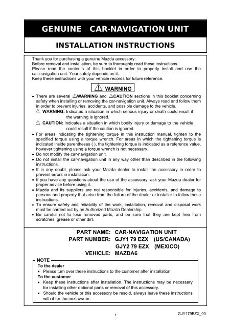
<strong>GENUINE</strong> <strong>CAR</strong>-<strong>NAVIGATION</strong> <strong>UNIT</strong><br />
INSTALLATION INSTRUCTIONS<br />
Thank you for purchasing a genuine Mazda accessory.<br />
Before removal and installation, be sure to thoroughly read these instructions.<br />
Please read the contents of this booklet in order to properly install and use the<br />
car-navigation unit. Your safety depends on it.<br />
Keep these instructions with your vehicle records for future reference.<br />
• There are several WARNING and CAUTION sections in this booklet concerning<br />
safety when installing or removing the car-navigation unit. Always read and follow them<br />
in order to prevent injuries, accidents, and possible damage to the vehicle.<br />
WARNING: Indicates a situation in which serious injury or death could result if<br />
the warning is ignored.<br />
CAUTION: Indicates a situation in which bodily injury or damage to the vehicle<br />
could result if the caution is ignored.<br />
• For areas indicating the tightening torque in this instruction manual, tighten to the<br />
specified torque using a torque wrench. For areas in which the tightening torque is<br />
indicated inside parentheses ( ), the tightening torque is indicated as a reference value,<br />
however tightening using a torque wrench is not necessary.<br />
• Do not modify the car-navigation unit.<br />
• Do not install the car-navigation unit in any way other than described in the following<br />
instructions.<br />
• If in any doubt, please ask your Mazda dealer to install the accessory in order to<br />
prevent errors in installation.<br />
• If you have any questions about the use of the accessory, ask your Mazda dealer for<br />
proper advice before using it.<br />
• Mazda and its suppliers are not responsible for injuries, accidents, and damage to<br />
persons and property that arise from the failure of the dealer or installer to follow these<br />
instructions.<br />
• To ensure safety and reliability of the work, installation, removal and disposal work<br />
must be carried out by an Authorized Mazda Dealership.<br />
• Be careful not to lose removed parts, and be sure that they are kept free from<br />
scratches, grease or other dirt.<br />
PART NAME:<br />
PART NUMBER:<br />
VEHICLE:<br />
WARNING<br />
<strong>CAR</strong>-<strong>NAVIGATION</strong> <strong>UNIT</strong><br />
GJY1 79 EZX (US/CANADA)<br />
GJY2 79 EZX (MEXICO)<br />
MAZDA6<br />
NOTE<br />
To the dealer<br />
• Please turn over these instructions to the customer after installation.<br />
To the customer<br />
• Keep these instructions after installation. The instructions may be necessary<br />
for installing other optional parts or removal of this accessory.<br />
• Should the vehicle or this accessory be resold, always leave these instructions<br />
with it for the next owner.<br />
1<br />
GJY179EZX_00
1. PARTS<br />
▼ PARTS LIST<br />
NOTE:<br />
• Before installation, verify that the kit includes all the following parts and that they are free of dirt, scratches,<br />
or damage.<br />
• GJY1 79 EZX (US/CANADA), GJY2 79 EZX (MEXICO)<br />
Part Part name Qty. Part Part name Qty. Part Part name Qty.<br />
Car-navigation<br />
unit<br />
1 Lid-NAVI 1<br />
Installation<br />
instruction<br />
1<br />
Owner’s<br />
manual<br />
1<br />
2. BEFORE INSTALLATION<br />
▼ REQUIRED TOOLS<br />
☆Phillips screwdriver ☆Torque wrench ☆Tape-wrapped flathead screwdriver<br />
☆Socket wrench (10mm) or Spanner wrench (10mm) ☆Clean rag (soft cloth)<br />
WARNING<br />
• To prevent short related accidents while performing procedures, disconnect the negative battery cable<br />
before beginning any work.<br />
• When disconnecting the connector, hold the connector itself to remove while pressing the connector lock.<br />
• Do not apply excessive force to the wiring harness as it could cause an open circuit.<br />
• When locking connectors, listen for a click that will indicate they are securely locked.<br />
• Be careful not to pinch the wiring harness. Otherwise, the harness may be broken.<br />
CAUTION<br />
• When removing and installing vehicle parts, make sure they are clean with no scratches. Also, be sure to<br />
cover the vehicle body with protectors or mats when removing/installing parts to prevent scratches and dirt.<br />
NOTE:<br />
• Refer to the applicable Workshop Manual for removal and installation of vehicle parts. Not following the<br />
procedures for removal/installation in the Workshop Manual could result in an accident or vehicle<br />
malfunction.<br />
• When the negative battery cable is removed, the clock, radio, trip meters and other memories will be<br />
erased. Before performing work, record the content of the memory.<br />
2
3. VEHICLE PARTS REMOVAL<br />
NOTE:<br />
• The following vehicle parts removal procedure is for left-hand drive vehicles. Perform the same procedure<br />
for right-hand drive vehicles.<br />
Negative battery cable disconnection<br />
1. Set the selector lever to P range.<br />
(AT vehicles only)<br />
Negative<br />
battery cable<br />
WARNING<br />
• When removing/installing the parts, park the vehicle on<br />
level ground and apply the side brake securely. Be sure to<br />
turn the ignition switch off, otherwise the vehicle can move,<br />
causing personal injury or vehicle damage.<br />
2. Disconnect the negative battery cable and wrap tape around it<br />
to insulate.<br />
WARNING<br />
• When the negative battery cable is connected during<br />
operation, it may cause electric shock or other personal<br />
injuries. Disconnect the negative battery cable before<br />
removal/installation.<br />
4. INSTALLATION<br />
Lid-Pocket<br />
<strong>CAR</strong>-<strong>NAVIGATION</strong> <strong>UNIT</strong> INSTALLATION<br />
Pocket Assy Removal<br />
1. Open the lid-pocket, remove the pins (1 each, left and right)<br />
from the underside of the lid-pocket, and remove the lid.<br />
• Dispose of the removed lid-pocket.<br />
Pin<br />
3
A<br />
2. Insert two pieces of wire or two bands (use hard acrylic bands)<br />
into the locations shown in the figure and secure both ends.<br />
(Figure shows bands being used)<br />
3. Pull the wires or bands in the direction shown in the figure and<br />
pull out the pocket assy.<br />
Wire or band<br />
A<br />
Lower panel<br />
Pocket<br />
assy<br />
Wire or band<br />
Vehicle<br />
front<br />
SEC. A-A<br />
Lower panel<br />
Harness<br />
clips<br />
4. Remove the wiring harness clips (2) on the back of the pocket<br />
assy.<br />
• Be careful not to apply excessive force to the wiring<br />
harness when removing the connectors.<br />
5. Disconnect the connectors (3).<br />
Connectors<br />
• Reuse harness clips(2).<br />
• Dispose of the removed pocket assy.<br />
+B/ACC<br />
connector<br />
USB<br />
connector<br />
Car-navigation unit<br />
Car-navigation unit Installation<br />
1. Connect the USB, GPS antenna, and +B/ACC connectors to the<br />
car-navigation unit.<br />
GPS antenna<br />
connector<br />
4
Harness clip installation hole<br />
2. Install the wiring harness clips(2).<br />
For<br />
+B/ACC<br />
Harness<br />
clip<br />
For GPS<br />
antenna<br />
harness<br />
clip<br />
+B/ACC harness clip<br />
Car-navigation unit<br />
GPS antenna<br />
harness clip<br />
Car-navigation unit<br />
3. Press the clips (4 locations) shown in the figure and install the<br />
car-navigation unit to the lower panel.<br />
Clips<br />
Clips Clips<br />
CAUTION<br />
• Be careful not to press the car-navigation unit when<br />
installing it.<br />
Clips<br />
Lower panel<br />
4. Install the lid-NAVI included in the kit.<br />
Pin<br />
Pin<br />
Lid-NAVI<br />
5
Hook A<br />
(1)<br />
Hook A<br />
Stay damper<br />
Hook A<br />
(1)<br />
(2)<br />
GPS CONNECTOR INSTALLATION(US/CANADA only)<br />
Glove compartment removal<br />
1. Push the glove compartment in the direction of the arrow (1)<br />
and hooks A.<br />
2. Pull the stay damper in the direction of the arrow (2) shown in<br />
the figure and remove the hook B.<br />
CAUTION<br />
• If the glove compartment is closed without being joined to<br />
the stay damper, the stay damper may be damaged. Verify<br />
that the stay damper is joined to the glove compartment<br />
before closeing the glove compartment.<br />
Glove compartment<br />
Stay damper<br />
Hook B<br />
(3)<br />
3. Pull down the glove compartment in the direction of the arrow<br />
(3).<br />
4. Pull the glove compartment in the direction of the arrow (4) and<br />
remove it while detaching hooks C.<br />
(4)<br />
Hook C<br />
GPS connector installation<br />
1. Disconnect the connector from the unit and connect it to the<br />
connector shown in the figure.<br />
2. Install the glove compartment in the reverse order of removal.<br />
GPS connector<br />
6
5. OPERATION CHECK<br />
1. Connect the negative battery cable and perform an operation check by referring to the owner’s manual<br />
applicable to the vehicle.<br />
2. If there is any malfunction, disconnect the negative battery cable and verify that each connector is properly<br />
connected and the wiring harnesses are not damaged or pinched, then perform the operation check again. If it<br />
does not operate normally, contact the dealer where the unit was purchased.<br />
■ After installing the car-navigation unit, verify the connections of the GPS antenna, +B/ACC, and USB<br />
connectors using the following procedure:<br />
Audio off screen<br />
Connection verification of GPS antenna connector<br />
1. Turn the ignition switch to the ON position.<br />
2. After the opening screen ends, the Audio off screen is<br />
displayed.<br />
3. Press the POWER/VOLUME dial to switch to the on screen.<br />
POWER/VOLUME dial<br />
Audio on screen<br />
SEEK UP button<br />
4. Press the POWER/VOLUME dial and SEEK UP button at the<br />
same time on the Audio on screen (press POWER/VOLUME<br />
dial a little earlier).<br />
POWER/VOLUME dial<br />
5. After switching to the AUDIO system screen, touch the<br />
buttons in the order of “1”, “5” and “ENTER” on the screen.<br />
7
6. After switching to the Vehicle and Navi Signal Check screen,<br />
touch “ “on the screen to switch the display screen to<br />
“NAVI GPS ANT”. Verify that “NAVI GPS ANT: OK” is<br />
displayed. If not OK, verify the connection condition again.<br />
7. Press the POWER/VOLUME dial to switch to the AUDIO<br />
screen.<br />
8. Switch the ignition off<br />
Audio off screen<br />
Connection verification of +B/ACC connector and USB connector<br />
1. Turn the ignition switch to the ON position.<br />
2. When the Audio off screen is displayed after the opening<br />
screen ends, press the NAV button.<br />
NAV button<br />
3. When the screen in the figure on the left is displayed, the<br />
connection verification is completed. If it is not displayed,<br />
verify the connection condition again.<br />
• The procedure from this screen is performed by a user.<br />
This procedure ends on this screen.<br />
• If the continue button is pressed, perform the “Reset<br />
procedure (Pg.9)”.<br />
Negative battery cable<br />
4. Switch the ignition off.<br />
5. Connect the negative battery cable.<br />
Tightening torque: 4.0-6.0 N・m<br />
• Refer to “Required servicing after disconnecting/connecting<br />
negative battery cable” in the vehicle workshop manual or<br />
the owner’s manual to restore the vehicle functions.<br />
8
Reset procedure<br />
• This procedure is in Step 3 of, “Connection verification of<br />
+B/ACC connector and USB connector (Pg. 8)”, and is<br />
implemented only if the “Continue” button is pressed by<br />
mistake and the screen advances too far.<br />
1. Touch "No”.<br />
2. Touch “Join Map Share”.<br />
3. Touch “Continue”.<br />
4. Touch “Yes”.<br />
5. Touch “I agree”.<br />
9
6. Touch the screen.<br />
7. Touch “Setting”.<br />
8. Touch the location shown in the figure.<br />
9. Touch “Reset factory setting”.<br />
10. Touch “Yes”.<br />
10
11. Touch “Yes”.<br />
12. Setting is finished when “Welcome” screen appears.<br />
13. Switch the ignition off.<br />
11
Date , ,<br />
VIN<br />
Person in<br />
charge<br />
Checked<br />
Approved<br />
INSTALLATION<br />
INSPECTION<br />
SHEET<br />
MAZDA6<br />
Car-navigation unit<br />
GJY1 79 EZX (US/CANADA)<br />
GJY2 79 EZX (MEXICO)<br />
Perform the following inspections<br />
1. Inspection items after installation<br />
Check<br />
• Verify the fitting between the vehicle part and the installed part, and inspect for damage or<br />
dirt.<br />
• When connecting connectors, verify the connection again to prevent poor connection or<br />
mis-connection. (Insert two times.)<br />
Check<br />
2. Vehicle parts reinstallation<br />
Inspected part<br />
Negative battery terminal<br />
Function restore procedure after<br />
removal/installation of battery<br />
Inspection<br />
item<br />
Torque<br />
change<br />
Operation<br />
Inspection<br />
Is the nut for the negative battery terminal tightened to<br />
the specified torque<br />
Have the vehicle’s functions been restored by referring<br />
to “Required servicing after disconnecting/connecting<br />
negative battery cable”, in the vehicle workshop manual<br />
or the owner's manual<br />
Check<br />
3. Installation of accessory, operation check<br />
Inspection<br />
Inspected part<br />
item<br />
Inspection<br />
Check<br />
Car-navigation unit Check Was “5. Operation check” performed<br />
The term of validity for this sheet : 3 year