Coilover Kit MAZDASPEED.pdf - RX8Club.com
Coilover Kit MAZDASPEED.pdf - RX8Club.com
Coilover Kit MAZDASPEED.pdf - RX8Club.com

You also want an ePaper? Increase the reach of your titles
YUMPU automatically turns print PDFs into web optimized ePapers that Google loves.
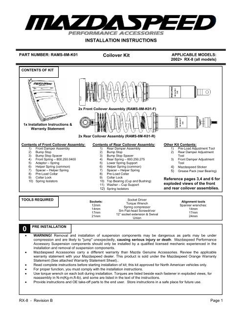
INSTALLATION INSTRUCTIONS<br />
PART NUMBER: RAMS-8M-K01 <strong>Coilover</strong> <strong>Kit</strong> APPLICABLE MODELS:<br />
2002> RX-8 (all models)<br />
CONTENTS OF KIT<br />
2x Front <strong>Coilover</strong> Assembly (RAMS-8M-K01-F)<br />
1x Installation Instructions &<br />
Warranty Statement<br />
2x Rear <strong>Coilover</strong> Assembly (RAMS-8M-K01-R)<br />
Contents of Front <strong>Coilover</strong> Assembly:<br />
1) Front Damper Assembly<br />
2) Bump Stop<br />
3) Bump Stop Spacer<br />
4) Front Spring – 800.250.0400<br />
5) Adaptor – Spring<br />
6) Helper Spring (<strong>com</strong>mon)<br />
7) Spacer – Helper Spring<br />
8) Pre-Load Collar<br />
9) Collar Lock<br />
10) Spring Isolators<br />
Contents of Rear <strong>Coilover</strong> Assembly:<br />
1) Rear Damper Assembly<br />
2) Bump Stop<br />
3) Bump Stop Spacer<br />
4) Rear Spring – 800.250.275<br />
5) Lower Spring Support<br />
6) Helper Spring (<strong>com</strong>mon)<br />
7) Spacer – Helper Spring<br />
8) Pre-Load Collar<br />
9) Collar Lock<br />
10) Top Bearing (Cup and Bushing)<br />
11) Washer – Cup Support<br />
12) Spring Isolators<br />
Other <strong>Kit</strong> Contents:<br />
1) Pre-Load Adjustment Tool<br />
2) Rear Damper Adjustment<br />
Tool<br />
3) Front Damper Adjustment<br />
Tool<br />
4) Mazdaspeed Sticker<br />
5) Grease Pack (rear Bearing)<br />
Reference pages 3,4 and 6 for<br />
exploded views of the front<br />
and rear coilover assemblies.<br />
TOOLS REQUIRED<br />
Sockets:<br />
12mm<br />
14mm<br />
17mm<br />
21mm<br />
Socket Driver<br />
Torque Wrench<br />
Spring <strong>com</strong>pressor<br />
Sm Flat-head Screwdriver<br />
12“ socket extension & Swival<br />
Union<br />
Alignment tools<br />
Spanner wrenches:<br />
14mm<br />
17mm<br />
24mm<br />
0<br />
PRE INSTALLATION<br />
• WARNING! Removal and installation of suspension <strong>com</strong>ponents may be dangerous as parts may be under<br />
<strong>com</strong>pression and are likely to "jump" unexpectedly, causing serious injury or death. Mazdaspeed Performance<br />
Accessory Suspension <strong>com</strong>ponents should only be installed by a qualified licensed mechanic experienced in the<br />
installation and removal of suspension <strong>com</strong>ponents.<br />
• Mazdaspeed Accessories carry a different warranty than Mazda Genuine Accessories. Review the applicable<br />
warranty statement with your Mazdaspeed dealer. This product is sold under the Mazdaspeed Orange Warranty<br />
Statement (See attached Warranty Statement Sheet)..<br />
• Read <strong>com</strong>plete instructions before starting installation of kit; this kit approved for North American vehicles only.<br />
• For proper function, you must <strong>com</strong>ply with the installation instructions.<br />
• Use torque wrench on each bolt during installation. Torques are listed beside each fastener in exploded views, for<br />
reassembly in N-m(Kg-m,ft-lb), and some are listed in the text of the instructions.<br />
• Provide instructions and OE take-off parts to the end user. Store instructions in a safe place for future use.<br />
RX-8 - Revision B Page 1
1a<br />
CAUTION:<br />
Mazdaspeed RX8 <strong>Coilover</strong> <strong>Kit</strong> Installation Instructions<br />
FRONT DAMPER/SPRING ASSMEBLY REMOVAL<br />
• Performing the following procedures without first removing the ABS wheel-speed sensor may possibly<br />
cause an open circuit in the harness if it is pulled by mistake. Before performing the following procedures,<br />
remove the ABS wheel-speed sensor (axle side) and fix it to an appropriate place where the sensor will not<br />
be pulled by mistake while installing suspension on the vehicle. Also remove the brake hose bracket (1)<br />
attachment to the upper control arm.<br />
1. With the front of the car off the ground and the suspension in full-droop, loosen lower attachment nut E and<br />
remove the upper control arm pivot bolts B and C (It may be necessary to remove the bolt from the brake<br />
line bracket located behind the control arm bolt at position B in order to <strong>com</strong>pletely remove the bolt).<br />
2. Remove the stabilizer bar from the lower control arm.<br />
3. Remove the 3 nuts that attach the upper mount to the shock tower (located under the hood).<br />
4. Remove bolt D, push down on the damper assembly so the upper mount studs clear their attachment<br />
holes, and carefully pull outboard on damper and upper control arm until the damper/spring assembly<br />
slides up and out. Do not put any tension on the brake hose which is still connected to the chassis and<br />
caliper.<br />
Figure A: Front Suspension Assembly<br />
RX-8 - Revision B Page 2
1b<br />
Mazdaspeed RX8 <strong>Coilover</strong> <strong>Kit</strong> Installation Instructions<br />
FRONT DAMPER/SPRING ASSMEBLY TEAR-DOWN & BUILD-UP<br />
WARNING: If removed incorrectly the shock and spring could fly off under pressure, causing injury or death.<br />
Remove the piston rod nut carefully after spring is <strong>com</strong>pressed and as follows. Secure the shock absorber in<br />
the spring <strong>com</strong>pressor before removing the piston rod nut. Read spring <strong>com</strong>pressor instructions before<br />
attempting to disassemble.<br />
Figure B: Spring Compressor<br />
WARNING: Do NOT use an impact wrench on the top nut!<br />
5. Install the spring/damper assembly into the spring<br />
<strong>com</strong>pressor (re<strong>com</strong>mended to use a piece of cloth in order<br />
to prevent the coil spring from being scratched).<br />
6. Compress the coil spring using the spring <strong>com</strong>pressor per<br />
its instructions and remove the piston rod nut.<br />
7. Carefully remove upper mount and the shock absorber<br />
from the spring. Make sure not to loose pieces of the<br />
assembly.<br />
8. Carefully de-<strong>com</strong>press the spring per the spring<br />
<strong>com</strong>pressor instructions.<br />
9. Use the upper mount, rubber damper isolators, upper<br />
washer and upper nut from the disassembled OE<br />
spring/damper assembly on the new coilover assembly per<br />
below.<br />
Figure C: Completed Front RX8 <strong>Coilover</strong> Assembly<br />
(1) Upper Nut (off OE unit)<br />
(2) Upper Washer (off OE unit)<br />
(3) Upper Damper Isolator (off OE unit)<br />
(4) Upper Mount (off OE unit)<br />
(5) Spacer – Isolator (off OE unit)<br />
(6) Lower Isolator (off OE unit)<br />
Only New <strong>Coilover</strong> Parts Below<br />
(7) Lower Washer (Supplied in <strong>Kit</strong>)<br />
(8) Adaptor – Front Spring<br />
(9) Spring Isolator (same as lower)<br />
RX-8 - Revision B Page 3
Mazdaspeed RX8 <strong>Coilover</strong> <strong>Kit</strong> Installation Instructions<br />
(10) Helper Spring<br />
(11) Spacer – Spring (same as rear)<br />
(12) Front Spring – 800.250.0400<br />
(13) Spacer – Bump Stop<br />
(14) Bump Stop<br />
(15) Spring Isolator (same as upper)<br />
(16) Pre-Load Collar<br />
(17) Collar Lock<br />
(18) Front Damper<br />
1c<br />
FRONT DAMPER/SPRING INSTALLATION<br />
WARNING: Do not use an impact wrench on the top nut<br />
10. Re-assemble in reverse order, but only snug (do not apply torque) either of bolts B or nut E (Figure A) until<br />
the vehicle is on the ground. Failing to do so could result in pre-mature failure of the rubber bushings, and<br />
will force the vehicle to sit higher. All torques, with the exceptions to the ones below, are shown in Figure<br />
A.<br />
Torque for Stabilizer bar nut is 43.1-60.8 N-m<br />
Torque for front-upper mount-to-tower nuts is 29.4-39.8 N-m<br />
RX-8 - Revision B Page 4
Mazdaspeed RX8 <strong>Coilover</strong> <strong>Kit</strong> Installation Instructions<br />
2a<br />
REAR DAMPER/SPRING REMOVAL<br />
Figure<br />
D: Rear Suspension Assembly<br />
*Tip: It is easiest to do both sides together.<br />
1. Remove the trunk liners from the inside of<br />
the trunk, carefully, using a small flat-head<br />
screw driver or clip-removal tool.<br />
2. Remove both lateral support brackets (6),<br />
each held on by 2 nuts and 2 bolts, then<br />
remove the two lower nuts (8) on each side.<br />
3. Mark the position of the cam bolt (3) for<br />
closer settings for the alignment.<br />
4. With the rear of the vehicle raised and the<br />
suspension in full-droop, remove bolts ,<br />
3, 4, and detach both sway bar brackets.<br />
5. With bolt 3 removed, rotate the rear link<br />
out of the way, pull down on the hub and<br />
carefully separate the damper from the<br />
lower mount.<br />
6. Whiles pulling down and out on the hub,<br />
extract the damper assembly by feeding it<br />
down through the lower-rear of the system.<br />
RX-8 - Revision B Page 5
2b<br />
Mazdaspeed RX8 <strong>Coilover</strong> <strong>Kit</strong> Installation Instructions<br />
REAR STRUT TEAR-DOWN & BUILD-UP<br />
WARNING: If removed incorrectly the shock and spring could fly off under pressure, causing injury or death.<br />
Remove the piston rod nut carefully after spring is <strong>com</strong>pressed and as follows. Secure the shock absorber in<br />
the spring <strong>com</strong>pressor before removing the piston rod nut. Read spring <strong>com</strong>pressor instructions before<br />
attempting to disassemble.<br />
6. Install the damper/spring assembly into the spring <strong>com</strong>pressor (re<strong>com</strong>mended to use a piece of cloth in<br />
order to prevent the coil spring from being scratched)-(See Figure B).<br />
7. Compress the coil spring using the spring <strong>com</strong>pressor per its instructions and remove the piston rod nut.<br />
8. Carefully remove upper mount and the shock absorber from the spring. Make sure not to loose pieces of the<br />
assembly.<br />
9. Carefully de-<strong>com</strong>press the spring per the spring <strong>com</strong>pressor instructions.<br />
10. Use the upper mount, upper nut, upper insulator and upper washer from the disassembled OE<br />
spring/damper assembly in the new coilover assembly per below.<br />
Figure E: Rear RX8 <strong>Coilover</strong> Assembly<br />
(1) Upper Nut (off OE unit)<br />
(2) Upper Washer (off OE unit)<br />
(3) Upper Damper Isolator (off OE unit)<br />
(4) Upper Mount (off OE unit)<br />
(5) Spherical Bearing (durable nylon)<br />
(6) Bearing Cup<br />
(7) Washer - Cup Support<br />
(8) Rear Damper Assembly<br />
(9) Collar Lock<br />
(10) Pre-Load Collar (shown below collar lock)<br />
(11) Spring Isolator (seated below pre-load collar)<br />
(12) Rear Spring – 800.250.0275<br />
(13) Spacer – Spring<br />
(14) Helper Spring<br />
(15) Lower Spring Support (shown un-mounted)<br />
Bump Stop & Bump Stop Spacer pre-installed on damper<br />
2c<br />
REAR DAMPER/SPRING INSTALLATION<br />
WARNING: Do NOT use an impact wrench on the top nut<br />
11. Re-assemble in reverse order; making sure the damper adjustment window is facing inboard for accessibility. Snug, but<br />
do not torque bolts 3 or 5 (Figure D) until the vehicle is on the ground. Failing to do so could result in pre-mature failure<br />
of the rubber bushings, and will force the vehicle to sit higher. All torques are shown in Figure D.<br />
RX-8 - Revision B Page 6
Mazdaspeed RX8 <strong>Coilover</strong> <strong>Kit</strong> Installation Instructions<br />
3 RIDE HEIGHT AND DAMPER ADJUSTMENT<br />
1. When adjusting the vehicle height, make sure that the threads are clean and free of debris. After initial<br />
cleaning, move the perch 10 mm downwards, and then clean the area that you desire to adjust the perch<br />
(up or down).<br />
2. In the area where the piston rod and the sealing package meet may have oil and grease collected. This can<br />
happen during assembly of the damper or due to accumulation of streak oil. There is no reason for concern<br />
over this oil/grease collection.<br />
Ride Height Adjustments<br />
Permitted Ride Height Adjustment Range<br />
Technical Data<br />
Part #<br />
Model<br />
Approximate adjustment range of<br />
<strong>Coilover</strong> “Height” in mm<br />
Approximate wheel hub center to fender<br />
edge “Height” in mm<br />
Front: Rear: Front: Rear:<br />
min: max: min: max: min: max: min: max:<br />
RAMS-8M-K01 RX-8 228mm 250mm 225mm 250mm 325mm 345mm 325mm 345mm<br />
Re<strong>com</strong>mended lowering 230mm 225mm 342mm 345mm<br />
Damper adjustments:<br />
FRONT<br />
REAR<br />
Front:<br />
Adjustment located at top of<br />
shock rod – accessible<br />
under hood after crossbrace<br />
is removed or access<br />
hole is made.<br />
Rear:<br />
Located at the bottom of<br />
the shock rod – access<br />
window pointing inboard<br />
to vehicle when<br />
installed.<br />
Re<strong>com</strong>mended initial<br />
setting:<br />
Start at full<br />
counterclockwise,<br />
then adjust three turns<br />
clockwise.<br />
Re<strong>com</strong>mended<br />
initial setting:<br />
Start at full<br />
counterclockwise, then<br />
adjust seven clicks<br />
clockwise.<br />
Avoid setting the dampers to full hard (full clockwise) initially.<br />
Clockwise = Harder Counterclockwise = Softer<br />
*Clockwise is towards the back of the car on the passenger-rear and towards the front of the car on the driver-rear.<br />
RX-8 - Revision B Page 7
Mazdaspeed RX8 <strong>Coilover</strong> <strong>Kit</strong> Installation Instructions<br />
FRONT<br />
Item<br />
3 FINAL INSTALLATION NOTES<br />
Total toe-in<br />
SUSPENSION ALIGNMENT SPECIFICATIONS<br />
Tire [Tolerance ±4 mm {0.15 in}]<br />
Rim inner<br />
Steering angle [Tolerance ±3°]<br />
(mm<br />
{in})<br />
(mm<br />
{in})<br />
degree<br />
Specification<br />
2 {0.08}<br />
1.4±1.1<br />
{0.06±0.04}<br />
0°11'±11′<br />
Inner 38°42′<br />
Outer 32°54′<br />
Steering axis inclination (Reference value) 10°43′<br />
Camber<br />
[Tolerance<br />
±0.5°]<br />
Caster<br />
• It is <strong>com</strong>mon for some vehicle suspensions to settle a few millimeters over the first 3000 miles of driving.<br />
• A vehicle alignment should be performed after assembly. Specifications should be set to re<strong>com</strong>mended<br />
specifications (below).<br />
• All <strong>com</strong>ponents that are controlled by vehicle ride height (headlights, etc.) must be adjusted as specified by the vehicle<br />
manufacturer instructions and procedures.<br />
• Only adjust ride height with the vehicle lifted off the ground so no pre-load is on the main spring.<br />
• It is strongly re<strong>com</strong>mended that the damper adjustment window on the rear damper be covered with a piece of<br />
weather-resistant tape to protect the mechanism from debris.<br />
[Tolerance<br />
±0.5°]<br />
Vehicle height: From the end of the front fender to the center of the wheel (mm) -<br />
re<strong>com</strong>mend measuring from the bottom of the rim to a marked point on the fender,<br />
then subtracting ½ of the rim diameter.<br />
Vehicle height: From the end of the front fender to the center of the wheel (mm) -<br />
re<strong>com</strong>mend measuring from the bottom of the rim to a marked point on the fender,<br />
then subtracting ½ of the rim diameter.<br />
356⎯365 -0°51′<br />
346⎯355 -1°21′<br />
336⎯345 -1°48′<br />
326⎯335 -2°00′<br />
315⎯325 -2°20′<br />
356⎯365 6°27′<br />
346⎯355 6°36′<br />
336⎯345 6°44′<br />
326⎯335 6°52′<br />
315⎯325 6°57′<br />
REAR<br />
Item<br />
Total toe-in<br />
Camber<br />
[Tolerance<br />
±0.5°]<br />
Tire [Tolerance ±4 mm {0.15 in}]<br />
Rim inner<br />
Vehicle height: From the end of the front fender to the center of the wheel (mm) -<br />
re<strong>com</strong>mend measuring from the bottom of the rim to a marked point on the fender,<br />
then subtracting ½ of the rim diameter.<br />
Specification<br />
RX-8 - Revision B Page 8<br />
(mm<br />
{in})<br />
(mm<br />
{in})<br />
3 {0.12}<br />
2.2±1.1<br />
{0.083±0.04}<br />
degree 0°17′±22′<br />
356⎯365 -1°38′<br />
346⎯355 -1°56′<br />
336⎯345 -2°14′<br />
326⎯335 -2°30′<br />
315⎯325 -2°40′
Mazdaspeed RX8 <strong>Coilover</strong> <strong>Kit</strong> Installation Instructions<br />
RX-8 - Revision B Page 9