Clay Vessel Manual - Velcon Filters
Clay Vessel Manual - Velcon Filters
Clay Vessel Manual - Velcon Filters

You also want an ePaper? Increase the reach of your titles
YUMPU automatically turns print PDFs into web optimized ePapers that Google loves.
CLAY VESSEL MANUAL<br />
(VC Series <strong>Vessel</strong>s)<br />
<strong>Velcon</strong> <strong>Filters</strong>, Inc.• 4525 Centennial Blvd. • Colorado Springs, CO 80919<br />
Phone: 719-531-5855 • Facsimile: 719-531-5690 • E-mail: vfsales@velcon.com<br />
www.velcon.com
TABLE OF CONTENTS<br />
GENERAL DESCRIPTION ..................................................................... 3<br />
INSTALLATION OF VESSEL.................................................................. 4<br />
ELEMENT INSTALLATION..................................................................... 5<br />
START-UP PROCEDURE ...................................................................... 6<br />
OPERATING INFORMATION................................................................. 7<br />
INSTALLATION INSTRUCTION 09-843…………………………………..10<br />
CLAY CANISTER ELEMENT DATA SHEET……………………………..11<br />
DISCLAIMER: This generic vessel manual is provided on the web for your<br />
information, with the understanding that each vessel manual sent out from<br />
<strong>Velcon</strong> is customized for the particular vessel, and contains accessory<br />
information not included in this document. This document makes reference<br />
to other pieces of literature, such as schematics and drawings that are added<br />
to the manual as needed depending on the vessel parameters.<br />
1507B-R1 08/02 PAGE 2<br />
PN 09-932
GENERAL DESCRIPTION<br />
The <strong>Velcon</strong> <strong>Clay</strong> <strong>Vessel</strong> that you have received consists of the vessel, clay elements<br />
and accessory equipment to meet your specific requirements. Descriptive literature<br />
covering the accessories can be found at the end of this manual.<br />
The <strong>Velcon</strong> <strong>Clay</strong> <strong>Vessel</strong> is specifically designed to remove surfactant material from<br />
the product being treated. The product enters from the inlet nozzle, rising vertically<br />
behind a baffle until it reaches the region above the top of the highest elements. The<br />
elements are arranged in vertical stacks rising up from a flat division plate. The fluid<br />
enters the outside of each element and flows through the packed clay media toward<br />
the center of the elements. The flow then goes downward to the outlet nozzle.<br />
The system must be correctly installed and operated to function properly. Please<br />
read the instructions in the manual and follow them carefully.<br />
<strong>Clay</strong> Canister Elements<br />
Attapulgus clay canisters are used for the removal of surfactants from jet fuel and<br />
other petroleum products.<br />
1507B-R1 08/02 PAGE 3<br />
PN 09-932
INSTALLATION OF VESSEL<br />
1. Identify the <strong>Clay</strong> <strong>Vessel</strong> inlet and outlet by the markings provided on the vessel<br />
piping. The <strong>Clay</strong> <strong>Vessel</strong> must be installed in the correct direction of flow to<br />
perform and to avoid damage to the system.<br />
2. INLET AND OUTLET PIPING should be carefully aligned to avoid stressing the<br />
<strong>Vessel</strong> connections during installation. Installation of shut-off valves on either side<br />
of the <strong>Clay</strong> <strong>Vessel</strong> is recommended so that it can be independently drained for<br />
cartridge change or inspection.<br />
CAUTION: STEPS 3 AND 4 SHOULD BE PERFORMED BEFORE<br />
REMOVING HINGE OR PIVOT MOUNTED COVER TO INSURE<br />
STABILITY OF THE CLAY HOUSING.<br />
3. Bolt the <strong>Clay</strong> <strong>Vessel</strong> to a stable base.<br />
4. Carefully install correct gaskets on the inlet and outlet connections and connect to<br />
the inlet and outlet piping.<br />
5. Connect any accessories that are not already installed. See Accessories Parts<br />
List and literature as required.<br />
6. Element and Mounting Hardware are packed separately. Open cover and install<br />
elements as directed in the installation instructions below<br />
7. Be sure the cover gasket is in place and properly aligned. Replace cover and<br />
secure tightly.<br />
8. NOTE: CLAY VESSELS MUST BE PROVIDED WITH PRESSURE RELIEF<br />
VALVES TO INSURE THAT PRESSURE THAT DEVELOPS FROM THERMAL<br />
EXPANSION OF THE FUEL, DUE TO TEMPERATURE INCREASES, WILL NOT<br />
DAMAGE THE VESSEL WHEN THE SYSTEM IS NOT OPERATING.<br />
1507B-R1 08/02 PAGE 4<br />
PN 09-932
ELEMENT INSTALLATION<br />
Your <strong>Clay</strong> <strong>Vessel</strong> was ordered with rigid canister elements. The installation<br />
instructions are outlined below. (See Internal Assembly Drawing):<br />
1. Place gaskets and mounting adapters over holes in bulkhead.<br />
2. Place tie rods through mounting adapters and screw into the crossbars across the<br />
bottom of the bulkhead.<br />
3. Secure mounting adapters in place using lock washers and hex nuts.<br />
4. Install first tier of elements, handle up. Do not drop elements. Lower carefully into<br />
place.<br />
5. Place center plates over elements.<br />
6. Repeat steps 4 and 5 for additional tiers of elements.<br />
7. Install final tier of elements.<br />
8. Place end-sealing caps over final tier of elements.<br />
9. Secure in place using gaskets, flat washers, lock washers and hex nuts. Tighten<br />
hex nut until gasket curls up slightly.<br />
10. Place lid gasket into groove provided, close vessel lid and bolt in place.<br />
1507B-R1 08/02 PAGE 5<br />
PN 09-932
START-UP PROCEDURE<br />
Prior to start-up, the valve handles should be placed in the following positions:<br />
1. <strong>Manual</strong> drain valves closed.<br />
2. <strong>Manual</strong> air eliminator valve open.<br />
3. The valves in the inlet and outlet piping should be closed.<br />
4. The pressure gauge valve to OFF position. For <strong>Clay</strong> <strong>Vessel</strong>s equipped with<br />
selector valves, this is done by turning the handle outward so that the<br />
arrow points toward the vessel.<br />
For information on operation of accessories, turn to Accessory Instruction<br />
in the back of the manual.<br />
After the valves have been positioned as outlined, the unit is ready to be<br />
filled.<br />
The following operating instructions can be used for initial start-up and<br />
for subsequent start-ups after installation of replacement elements or<br />
servicing of the unit.<br />
1. Start the system pump.<br />
2. Open the inlet valve slightly, allowing the clay housing to SLOWLY fill<br />
with fluid.<br />
3. If the unit is equipped with a manual air eliminator valve, leave the<br />
valve cracked open until the fluid flows from the opening; then close<br />
quickly. If equipped with an automatic air eliminator, the unit is filled<br />
when the eliminator stops flowing air.<br />
4. When the <strong>Clay</strong> <strong>Vessel</strong> is filled with fluid, SLOWLY open the valve on the<br />
outlet line. Then open the inlet valve fully.<br />
5. When the unit is in operation, take a differential pressure reading and<br />
record the reading. The differential pressure should be between 1 and 3<br />
psid depending on the purchase specification. If there is no differential<br />
pressure, the system should be shut down and the <strong>Clay</strong> <strong>Vessel</strong> inspected<br />
for broken seals or possibly elements left out. See Differential Pressure<br />
Reading, Page 7.<br />
1507B-R1 08/02 PAGE 6<br />
PN 09-932
OPERATING INFORMATION<br />
Below are the <strong>Velcon</strong> recommendations for operating procedures. Your Company<br />
Maintenance and/or Quality Control procedures may provide alternate<br />
instructions on these matters.<br />
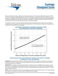
1. DIFFERENTIAL PRESSURE READINGS. Differential pressure is the difference<br />
between the pressure upstream and downstream of the <strong>Clay</strong> <strong>Vessel</strong>. Differential<br />
pressure increases when contaminant is filtered by the elements and causes flow<br />
restriction.<br />
(NOTE: A high differential pressure is a sign of the clay vessel becoming an<br />
expansive pre-filter vessel, and the clay cartridges are probably not removing much<br />
surfactant.)<br />
Readings should be taken when the system is flowing at maximum capacity. If<br />
the <strong>Clay</strong> <strong>Vessel</strong> is equipped with a direct reading differential pressure gauge, the<br />
reading shown on the gauge is the differential pressure across the <strong>Clay</strong> <strong>Vessel</strong>.<br />
If the <strong>Vessel</strong> is equipped with a pressure gauge and a selector valve, use the<br />
following procedure for determining differential pressure:<br />
A. Turn the handle to the outlet side so that the arrow points toward the inlet.<br />
Record gauge reading as "Inlet Pressure."<br />
B. Turn the handle toward the inlet side so that arrow points toward the outlet.<br />
Record gauge reading as "Outlet Pressure."<br />
C. Subtract outlet pressure from inlet pressure to determine differential pressure.<br />
D. Turn handle outward so that arrow points toward vessel, which is the "OFF"<br />
position. TO AVOID DAMAGE TO THE PRESSURE GAUGE, LEAVE THE<br />
HANDLE IN THE "OFF" POSITION WHEN READINGS ARE NOT BEING<br />
TAKEN.<br />
Differential pressure readings should be taken at least once during each operating<br />
week and more frequently in high throughput installations or when the differential<br />
pressure is increasing rapidly. Records of the differential pressure and throughput<br />
should be maintained to determine when cartridges should be changed.<br />
A sudden drop in pressure differential is an indication of a possible problem. Check<br />
first to be sure that readings were taken at equivalent flow rates. If so, shut the<br />
system down and open the <strong>Clay</strong> <strong>Vessel</strong> and inspect for damaged elements or seals.<br />
1507B-R1 08/02 PAGE 7<br />
PN 09-932
2. ELEMENT CHANGE REQUIREMENTS. <strong>Clay</strong> Elements should be changed<br />
whenever one of the following events occur:<br />
A. Differential pressure exceeds 15 psid.<br />
B. Effluent quality checks indicate the clay is spent and is no longer<br />
removing surfactant materials. (e.g. Unsatisfactory filter membrane color,<br />
MSEP, or IFT Readings)<br />
C. After one year of operation.<br />
3. ELEMENT CHANGE OR INSPECTION PROCEDURE.<br />
A. Shut off the pump.<br />
B. Close the inlet and outlet pipe valves.<br />
C. Open drain valves and remove product from the <strong>Clay</strong> <strong>Vessel</strong>.<br />
D. Open the manual air eliminator valve. This will permit the unit to drain<br />
faster.<br />
E. Open cover and inspect cover gasket. Replace gasket if it is damaged.<br />
F. Remove spent elements.<br />
G. Wipe off or wash down any foreign matter from the vessel interior.<br />
H. Install elements in accordance with instructions on Page 5.<br />
Check cover gasket for alignment, replace cover and secure tightly. The<br />
<strong>Clay</strong> <strong>Vessel</strong> is now ready for the start-up procedure.<br />
1507B-R1 08/02 PAGE 8<br />
PN 09-932
USE ONLY VELCON FILTERS INC. ELEMENTS IN THIS CLAY VESSEL. VELCON<br />
CANNOT WARRANT PERFORMANCE IF ANY OTHER MANUFACTURER’S<br />
ELEMENTS ARE USED.<br />
To reorder elements and replacement parts or to obtain further information contact<br />
your <strong>Velcon</strong> <strong>Filters</strong>, Inc. representative<br />
Or<br />
VELCON FILTERS, INC.<br />
4525 Centennial Blvd.<br />
Colorado Springs, CO 80919-3350<br />
Phone: 719-531-5855<br />
Fax: 719-531-5690<br />
E-mail: vfsales@velcon.com<br />
Web site: www.velcon.com<br />
1507B-R1 08/02 PAGE 9<br />
PN 09-932
4525 Centennial Blvd., Colorado Springs, CO 80919<br />
Phone: (719) 531-5855 FAX: (719) 531-5690<br />
e-mail: vfsales@velcon.com<br />
INSTALLATION<br />
Instructions<br />
CO-718CE – CLAY CANISTER ELEMENTS<br />
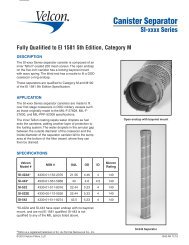
The CO-718CE is a canister type element which is equipped with a gasket at each end. To insure proper sealing at<br />
each end it is necessary to use a sealing plate between stacked elements. Installation procedures are as follows:<br />
1. Stop product flow, close inlet and outlet valves, open the air eliminator, and drain vessel completely down.<br />
2. Remove head bolts from head cover.<br />
3. Raise cover by raising hydraulic jack cover and swing back to one side of the vessel.<br />
4. Remove tie rod nuts, washers and top sealing caps.<br />
5. Remove old elements.<br />
6. Remove center plates and store with the sealing caps, the tie rod nuts, and washers.<br />
7. Remove next layer(s) of old elements.<br />
8. Clean vessel interior after all elements are removed.<br />
9. Remove new CO-718CE from plastic bag.<br />
NOTE: CO-718CE ELEMENTS CAN BE DAMAGED BY WATER. NEW ELEMENTS SHOULD BE<br />
PROTECTED FROM ANY WASHING DOWN OPERATION OR RAIN.<br />
10. Lower CO-718CE elements over the center rods to bottom of vessel. Bail handles for assisting in installing<br />
and removing the canisters should be on the upper end of the canisters. DO NOT DROP ELEMENTS.<br />
LOWER CAREFULLY.<br />
11. Place center plates over first tier of elements.<br />
12. Place CO-718CE elements on top of center plates.<br />
13. Install center plates on top of these elements if the vessel is a 3 high stack, otherwise go to Step 15.<br />
14. Install third tier of elements.<br />
15. Place sealing caps on top of final tier of elements.<br />
16. Place a rubber gasket, flat washer, lock washer and nut over each tie rod and securely fasten down. When<br />
rubber gasket starts to curl out from under flat washer, enough torque has been applied.<br />
17. Replace vessel cover and tighten down securely.<br />
18. Close drain valve, open air eliminator, crack open the inlet valve and fill the vessel SLOWLY.<br />
19. When vessel is full, fully open the inlet and outlet valves.<br />
1046-R3 02/00<br />
P/N 09-843
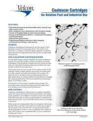
<strong>Clay</strong> Canister<br />
Elements<br />
CO-718 Series Cartridges for<br />
Fuel and Oil Treatment<br />
The <strong>Velcon</strong> CO-718 Series elements are intended for<br />
use in all clay treatment vessels designed for nominal<br />
7” x 18” cartridges. The treatment/purification medium<br />
is a special blend of low volatile materials (LVM) fuller’s<br />
earth compounded to provide the optimum balance<br />
between adsorptive capacity and water resistance. With<br />
their ability to prevent channeling and their high particle<br />
structure stability, the elements assure reliable<br />
performance and long life in the most exacting process<br />
applications.<br />
Jet Fuel Treatment – One of the most common uses<br />
for clay elements is to remove surfactants from jet fuels.<br />
Surfactants can carry over from the refinery process or<br />
be picked up when the jet fuel travels through multiproduct<br />
pipelines (corrosion inhibitors, gasoline additives,<br />
etc.). Surfactants will eventually disarm filter/separators,<br />
which are primarily designed to remove water from the<br />
jet fuel. By removing surfactants from the fuel, the clay<br />
elements protect the downstream filter/separators. Since<br />
clay removes the surfactants by an adsorbent (adhering)<br />
action, the fuel residence time, or time in contact with the<br />
clay, is very important for proper fuel treatment. Normally,<br />
a flow rate of about 6.5 gpm per 7” x 18” element is ideal<br />
for jet fuel.<br />
NOTE: For further information on clay, see data sheet<br />
#1223 in the Technical Information Section of the <strong>Velcon</strong><br />
catalog. See data sheet #1759, SWIFTKit ® , for information<br />
on how to determine when the clay elements should<br />
be changed.<br />
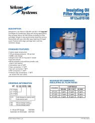
CO-718CE Canister<br />
CONSTRUCTION<br />
CO-718CE is a rugged canister element featuring<br />
aluminized steel endcaps and center-tube, polyester felt<br />
outerwrap and both interior and exterior media migration<br />
barriers. A wire bail provides for easy installation and<br />
removal. Buna-N gaskets at each end assure tight sealing.<br />
The improved construction offers high resistance to transit<br />
or handling damage and to differential pressures up<br />
to 100 psi.<br />
© 2002 <strong>Velcon</strong> <strong>Filters</strong>, Inc. 1231-R13 04/02
SPECIFICATIONS<br />
Length 18”<br />
Outer Diameter 7”<br />
Center Diameter 2 1 /4”<br />
Collapse Strength<br />
100 psi<br />
Interchange:<br />
Facet/Fram C-766-3<br />
Keene-LE-718<br />
APPLICATIONS<br />
Lubricating Oils<br />
Quench Oils<br />
Vacuum Pump Oils<br />
Hydraulic Fluids<br />
Jet Fuels<br />
Insulation Oils<br />
Aluminum and Stainless Steel Rolling Oils<br />
<strong>Velcon</strong> products are sold and serviced by a world-wide representative<br />
network. To order, contact Headquarters or your LOCAL REPRESENTATIVE:<br />
Due to <strong>Velcon</strong> <strong>Filters</strong>’ continuing product improvement, drawings, specifications and pictures are subject to change without notice.<br />
COMPANY HEADQUARTERS:<br />
<strong>Velcon</strong> <strong>Filters</strong>, Inc. 4525 Centennial Blvd.<br />
Colorado Springs, CO 80919-3350<br />
Phone: 1.800.531.0180<br />
Fax: 719.531.5690<br />
e-mail: vfsales@velcon.com<br />
www.velcon.com<br />
MANUFACTURING PLANTS LOCATED AT:<br />
Colorado Springs, Colorado<br />
Sylacauga, Alabama<br />
Harlingen, Texas<br />
OVERSEAS AFFILIATES:<br />
Frankfurt/M., W. Germany & Singapore<br />
Liquid Filtration<br />
and Separation<br />
Specialists