Lab # 4 - DrJJ - UiTM
Lab # 4 - DrJJ - UiTM
Lab # 4 - DrJJ - UiTM

Create successful ePaper yourself
Turn your PDF publications into a flip-book with our unique Google optimized e-Paper software.
Material Science<br />
PHY407<br />
Universiti Teknologi MA RA<br />
Fakulti Sains Gunaan<br />
Capacitors, Capacitance, Series &<br />
Parallel Circuit<br />
PHY407: A Physical Science Activity<br />
Name:____________________________ HP: ____________________ <strong>Lab</strong> # 4:<br />
Goal<br />
Today, you will determine how the capacitance depends on the plate separation. In addition,<br />
you will also determine how to find the effective capacitance when capacitances are<br />
connected in series and in parallel, respectively.<br />
Learning Outcomes<br />
At the end of today’s activity, students will be able to<br />
• Use a multimeter to measure capacitance of a variety of capacitors.<br />
• Use a multimeter to measure, the effective capacitance for 2 capacitors connected in<br />
series,<br />
• Use a multimeter to measure 2 capacitors connected in parallel<br />
• Use a multimeter to measure 4 capacitors connected in series-parallel combination.<br />
• Obtain a simple relationship to determine effective capacitances in a series or in a<br />
parallel configuration.<br />
• Determine the relationship between capacitance of a parallel plate capacitor and the<br />
plate separation.<br />
Background Information<br />
Background:<br />
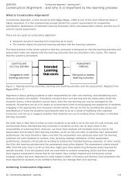
Electrostatics involved the study of excess charges on conductors and<br />
nonconductors and is usually explained by the presence of electric field which gives rise to<br />
coulomb forces and acceleration or displacement of charges. Charges that are in motion<br />
constitutes flowing current. One way of making charges to move is by using a battery or a<br />
direct current (DC) power supply which can maintain a constant electromotive force (EMF) or<br />
potential difference across its terminals. In addition to batteries as sources of charges, in<br />
electronic circuits, a device known as capacitors are used to store charges. The difference<br />
between batteries and capacitors is that capacitors are not constant source of charges.<br />
Capacitors need to be charged up by batteries or power supplies and once charged, it will<br />
hold the charges by maintaining a potential<br />
difference across its ends. Once used, it will be<br />
depleted of charges and will need to be charged<br />
again. The most common and easiest capacitor to<br />
Parallel plate<br />
capacitor<br />
Symbol for a<br />
capacitor<br />
analyze is the parallel plate capacitor. This type of<br />
capacitor is easy to construct and use simple<br />
mathematical calculations and basic physical<br />
reasoning. A parallel plate capacitor is commonly<br />
represented as shown in the figure to the left.<br />
Created by Dr. JJ, FSG, <strong>UiTM</strong> Shah Alam Page 1 of 5
Material Science<br />
PHY407<br />
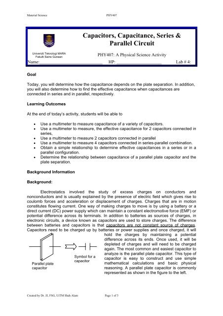
The amount of charges that capacitors can store, have been shown to be directly<br />
proportional to the potential difference applied across its plates, q∝V<br />
. When the<br />
proportionality is replaced by an equality, a constant is placed in front of the variable and that<br />
constant has been determined to be the capacitance C and so the relationship can now be<br />
written as q=<br />
CV where C is known as the capacitance of the capacitor. Hence, the<br />
q<br />
1 Coulomb<br />
capacitance is C = and measured in units of Farad where 1 Farad =<br />
. The<br />
V<br />
Volts<br />
normal strength of capacitors are in the range of picofarad (1 pF = 10 -12 F) to microfarad (1<br />
µF = 10 -6 F) to millifarad (1 mF = 10 -6 F). Hence the higher the emf of a battery used to<br />
charge up the plates, the more charges that will be stored. In fact, when a capacitor stores<br />
charges it actually stores electrical energy and it can be shown that the average energy<br />
1 2<br />
stored is, E = CV or can also be written in terms of the charge as<br />
2<br />
1 2 1 q 2 1<br />
E = CV = V = qV .<br />
2 2V<br />
2<br />
The capacitance of capacitors is just a constant value which depends on the area of<br />
the plates, the separation of the plates and the nonconducting material inserted between the<br />
plates. It has been shown before that the capacitance is directly proportional to the plate’s<br />
area and the relative permittivity of the material of the medium between the plates, C ∝ ε A.<br />
−12 2 2<br />
If the medium is just air, the relative permittivity is just ε0 = 8.85×<br />
10 C / Nm , the relative<br />
permittivity for free space. Today, you will determine how the capacitance depends on the<br />
plate separation. In addition, you will also determine how to find the effective capacitance<br />
when capacitances are connected in series and in parallel, respectively.<br />
Investigation 1-Capacitors & Capacitances<br />
Student Activity<br />
Prediction 1.1:<br />
Given 5 different capacitors, predict if a multimeter set to the capacitance<br />
mode, will read the same or different capacitance values compared to the<br />
values written on the capacitor.<br />
Activity 1.1:<br />
Read the capacitance printed on the capacitors. For each of the capacitors, use a<br />
multimeter in the capacitance mode to measure the capacitances by touching the<br />
ends of the probes to the ends of the capacitors. Record your reading. Then reverse<br />
the polarity of the probe used to touch the ends of the capacitor and observe the<br />
reading again. Record the reading and compare with the reading printed on the<br />
capacitor. Tabulate the data.<br />
Capacitance printed on<br />
capacitor, pF<br />
Measured<br />
Capacitance; pF<br />
Measured Capacitance<br />
(Reversed polarity); pF<br />
Created by Dr. JJ, FSG, <strong>UiTM</strong> Shah Alam Page 2 of 5
Material Science<br />
PHY407<br />
Questions<br />
1. Does changing polarity of the meter probes produce different values Why or why<br />
not<br />
2. Which reading, the printed values or the multimeter reading is more reliable Explain.<br />
Prediction 1.2: (Series & Parallel Circuit)<br />
i) What do you physically do when you connect capacitances in series or in<br />
parallel<br />
ii) What happens to the effective or total capacitance when they are added in<br />
series and in parallel respectively<br />
Activity 1.2:<br />
i) Using a multimeter in resistance mode, check which points on the circuit<br />
board produce zero reading and the points that produce infinite reading. Ii)`<br />
ii) Connect the capacitors you used in activity 1.1 on the circuit board. These are<br />
as shown in the 5 configurations in Figure 1. Then use the multimeter to<br />
measure the effective capacitances. Record your reading.<br />
A<br />
100 pF<br />
A<br />
100 pF<br />
A<br />
100 pF 100 pF<br />
A<br />
100 pF 10 nF<br />
100 pF<br />
A<br />
100 pF<br />
B<br />
10 nF<br />
B<br />
B<br />
B<br />
B<br />
100 pF 100 pF<br />
C<br />
C AB = __ pF<br />
C BC = __ pF<br />
C AC = __ pF<br />
C<br />
C AB = __ pF<br />
C BC = __ nF<br />
C AC = __ nF<br />
100 pF<br />
D<br />
C AB = _____ pF C AB = _____ nF C AB = __ pF<br />
C BC = __ pF<br />
C CD = __ pF<br />
C AD = __ pF<br />
C<br />
Questions<br />
1. What happens to the effective capacitance when capacitances are connected<br />
in series Does it increase or decrease Can you write down a possible<br />
mathematical relation to determine the effective capacitance Is it consistent<br />
1 1 1<br />
with, = + + ..<br />
1 <br />
Ceq, series<br />
C1 C2<br />
Cn<br />
2. What happens to the effective capacitance when capacitances are connected<br />
in parallel Does it increase or decrease Can you write down a possible<br />
mathematical relation to determine the effective capacitance Is it consistent<br />
with, Ceq, parallel<br />
= C1+ C2 + .. Cn<br />
<br />
3. What happens to the effective capacitance when capacitances are connected<br />
in series-parallel combination<br />
Created by Dr. JJ, FSG, <strong>UiTM</strong> Shah Alam Page 3 of 5
Material Science<br />
PHY407<br />
Investigation 2 – Capacitance<br />
Prediction 2.1 (Refer to the figure below)<br />
i) What type of excess charge will build up on the metal plate that is attached to<br />
the negative terminal of the battery What type of excess charge will build up<br />
on the plate that is connected to the positive terminal of the battery Explain.<br />
ii) Can the excess positive charges on one plate of a charged parallel-plate<br />
capacitor exert forces on the excess negative charges on the other plate<br />
Explain.<br />
iv) Once the plates have been charged up and the wires removed from the<br />
batteries, how will the capacitance change when the distance between the<br />
plates is increased<br />
iv) Once the plates have been charged up and the wires removed from the<br />
batteries, how will the charge, the potential difference between the plates, the<br />
electric field and the total energy stored by the capacitor change when the<br />
distance between the plates is increased<br />
+ V -<br />
DMM<br />
Activity 2.1:<br />
i) Connect the circuit as shown in the figure. Be sure the multimeter dial is set to<br />
read capacitance.<br />
ii) Beginning with the plate separation of 1 mm, record the value of the<br />
capacitance as the separation is increased by 1 mm.<br />
Plate Separation, d<br />
mm<br />
1<br />
2<br />
3<br />
4<br />
5<br />
6<br />
7<br />
8<br />
9<br />
10<br />
11<br />
12<br />
13<br />
14<br />
15<br />
16<br />
17<br />
18<br />
Capacitance, C<br />
Created by Dr. JJ, FSG, <strong>UiTM</strong> Shah Alam Page 4 of 5
Material Science<br />
PHY407<br />
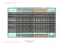
iii) Graph the capacitance on the y-axis and the plate separation, d, on the x-<br />
axis. Then observe and conclude the relationship that you see. Find the slope<br />
and identify what physical quantity, the slope or its inverse, represents. Is it<br />
ε<br />
0<br />
consistent with C = A <br />
d<br />
Questions<br />
1. What happens to the capacitance when the separation is changed<br />
2. What can you conclude about the capacitance-plate separation relationship<br />
from the graph that you plotted<br />
3. How is the slope of the line useful to you<br />
4. Is the slope or its inverse comparable to the product of A<br />
0<br />
Created by Dr. JJ, FSG, <strong>UiTM</strong> Shah Alam Page 5 of 5