CSS Mar_09 WEB.qxd - Nianpa
CSS Mar_09 WEB.qxd - Nianpa
CSS Mar_09 WEB.qxd - Nianpa

Create successful ePaper yourself
Turn your PDF publications into a flip-book with our unique Google optimized e-Paper software.
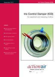
May 2010<br />
<strong>CSS</strong> ES Rated Fire Damper<br />
<strong>CSS</strong> Damper<br />
<strong>CSS</strong> Smoke ES Rated Fire Damper<br />
Features<br />
• Tested to EN 1366-2.<br />
• Achieved 2 hour ES<br />
classification for both horizontal<br />
and vertical application.<br />
• Suitable for standard or 50mm<br />
insulated circular ductwork.<br />
• Available in standard duct sizes<br />
100mm to 355mm diameter.<br />
Dampers Controls Fancoils<br />
Ruskin Air Management Limited<br />
www.ruskinuk.co.uk
<strong>CSS</strong> ES Rated Fire Damper<br />
Introduction<br />
Specification<br />
The <strong>CSS</strong> circular smoke and fire damper<br />
is the latest development to join the<br />
Actionair’s innovative and tested range of<br />
damper products.<br />
The damper has been developed for<br />
installing into standard circular spiral<br />
duct systems where the duct passes<br />
through, up to 2 hour rated walls. The<br />
easy fit flange system makes the<br />
installation quick and simple.<br />
The <strong>CSS</strong> is available in a number of<br />
circular sizes to suit 50mm thermal<br />
insulated or non insulated ductwork, and<br />
is supplied with a factory fitted control<br />
mode, with Electrical Thermal Release<br />
(ETR) as utilised on our Smoke, Vent /<br />
Shield ranges.<br />
The Range<br />
The <strong>CSS</strong> circular range of Quality<br />
Engineered Dampers are suitable for air<br />
conditioning and ventilation systems<br />
requiring up to 2 hour fire protection.<br />
These circular bladed dampers are fail –<br />
safe spring close with factory fitted<br />
electrical reset control modes.<br />
Blade and Casing<br />
Features<br />
The circular fire damper incorporates a<br />
unique and patented seal that provide ES<br />
leakage performance at both ambient and<br />
fire conditions. It is housed in a galvanised<br />
case complete with two installation<br />
flanges for easy fitting into stud and solid<br />
wall applications.<br />
Sizes Available<br />
100, 125, 150, 160, 200, 250, 300, 315,<br />
350 and 355. Manufactured to<br />
BS EN 1506.<br />
Control Options<br />
A choice of two motorised compact<br />
Control Modes 5 (24 volt) and 6 (230 volt)<br />
are available, these are optimised motor /<br />
spring return type with remote resetrelease<br />
facilities, with volt free contacts for<br />
provision of external indication, monitoring<br />
and control by means of Actionpac<br />
damper control system, or by suitable<br />
alternative proprietary control format.<br />
Factory fitted and fully tested Control<br />
Modes are located outside of the<br />
ductwork for easy access and installation.<br />
Smoke/Fire (fail-safe closed) version<br />
The Actionair <strong>CSS</strong> Circular automatic<br />
Smoke ES rated Fire dampers with a<br />
single galvanised steel blade<br />
incorporating patented seal to provide<br />
both ambient and fire rated low leakage.<br />
Damper conforms to EN1366-2.<br />
Classification E120 and ES120 and<br />
damper casings conform to BSEN1506<br />
for both horizontal and vertical<br />
application. 1 pair of 1.2mm galvanised<br />
steel hinged Installation flanges are<br />
provided with each damper. The Actionair<br />
Factory fitted Compact electrical control<br />
mode with thermal sensing to provide<br />
Fail-Safe-Closed operation.<br />
Electrical actuators are fitted with<br />
halogen free low smoke and fume<br />
cables. They have 60 second reset time<br />
and a 20 second release time. Each<br />
actuator has a 72°C rated electrical<br />
thermal release (ETR). The ETR<br />
incorporates a safety electrical interlock<br />
that only permits actuator operation<br />
when correctly fitted.<br />
A green ‘Healthy’ indication lamp is built<br />
into the ETR to give a simple and clear<br />
visual check that the actuator is<br />
receiving power, the ETR is correctly<br />
fitted and the thermal fuse is intact.<br />
A manual test switch allowing periodic<br />
operation of the damper for testing<br />
purposes simulates actuator fail-safe<br />
Application<br />
Parameters<br />
<strong>CSS</strong> circular smoke and fire dampers can<br />
be incorporated in Smoke/Shield systems<br />
or within exclusive circular ventilation<br />
systems as a competitively priced<br />
alternative to the circular Smoke/Shield<br />
601 dampers.The <strong>CSS</strong> dampers can be<br />
used where the operating total system<br />
pressure is up to<br />
release under fire/smoke conditions.<br />
End switches are provided with each<br />
mode for reset and release monitoring.<br />
The <strong>CSS</strong> Damper and selected<br />
Compact Control Mode (Mode 5 –24V,<br />
or Mode 6 – 230V) as supplied by<br />
Actionair.<br />
Vent (fail-safe open) version<br />
The Actionair <strong>CSS</strong> Circular Vent<br />
automatic smoke release dampers with<br />
a single galvanised steel blade<br />
incorporating patented seal to provide<br />
ambient low leakage.<br />
Damper casings conform to BSEN1506.<br />
1 pair of 1.2mm galvanised steel hinged<br />
Installation flanges are provided with<br />
each damper.<br />
The Actionair Factory fitted Compact<br />
electrical control mode with fail-safe<br />
open operation upon removal of electrical<br />
power.<br />
Electrical actuators are fitted with<br />
halogen free low smoke and fume<br />
cables. They have 60 second reset time<br />
and a 20 second release time.<br />
End switches are provided with each<br />
mode for reset and release monitoring.<br />
The <strong>CSS</strong> Damper and selected Vent<br />
Compact Control Mode (Mode 5 –24V,<br />
or Mode 6 – 230V) as supplied by<br />
Actionair.<br />
1500 Pascals and duct velocities to<br />
15m/second.<br />
The <strong>CSS</strong> round damper blade is normally<br />
open and fail-safe to the closed position.<br />
This product is ES rated.<br />
Actionair <strong>CSS</strong> dampers are designed for<br />
application in normal dry filtered air<br />
systems. If exposed to fresh air intakes<br />
and / or inclement conditions, the<br />
dampers should be subject to a planned<br />
inspection programme.<br />
2 www.actionair.co.uk
<strong>CSS</strong> ES Rated Fire Damper<br />
Control Modes<br />
Mode 5 <strong>CSS</strong> (24V System)<br />
Power On – Damper motors open.<br />
Power Off – Spring closure.<br />
Electrical Thermal Release.<br />
External mechanical position indicator<br />
with pointer.<br />
Release Time ≈ 20 secs.<br />
Reset Time ≈ 60 secs.<br />
AC/DC 24V<br />
50 / 60 Hz<br />
M<br />
BLACK<br />
WHITE<br />
1<br />
2<br />
1<br />
2<br />
3<br />
–<br />
+<br />
SUPPLY<br />
24V AC or DC<br />
TYPICALLY 5W (MOTORING)<br />
2.5W (RESET)<br />
CONTACT MADE BETWEEN<br />
1 AND 2 WHEN DAMPER<br />
FULLY RELEASED<br />
(Connect 24V via a safety isolating<br />
transformer.)<br />
* Not fitted to Vent versions.<br />
7 V A<br />
5 / 2.5 W<br />
Imax<br />
5.8A @ 5ms<br />
AC<br />
250V<br />
6(3)A<br />
4<br />
5<br />
6<br />
CONTACT MADE BETWEEN<br />
4 AND 6 WHEN DAMPER<br />
FULLY RESET<br />
– 30...+50 C<br />
CONTINUOUS<br />
*<br />
TF 72 C<br />
ELECTRICAL THERMAL RELEASE<br />
(MUST BE FITTED TO DUCTING<br />
FOR DAMPER OPERATION).<br />
NOT AVAILABLE VENT VERSION<br />
(SPRING BIASED TEST SWITCH)<br />
DIAGRAM SHOWS ACTUATOR IN FULLY RELEASED STATE<br />
Mode 6 <strong>CSS</strong> (230V System)<br />
Power On – Damper motors open.<br />
Power Off – Spring closure.<br />
Electrical Thermal Release.<br />
External mechanical position indicator<br />
with pointer.<br />
Release Time ≈ 20 secs.<br />
Reset Time ≈ 60 secs.<br />
(To isolate from main power supply, the<br />
system must incorporate a device which<br />
disconnects the phase conductors, with a<br />
least 3mm contact gap.)<br />
* Not fitted to Vent versions.<br />
AC 230V<br />
50 / 60 Hz<br />
7 V A<br />
5 / 3 W<br />
– 30...+50 C<br />
CONTINUOUS<br />
AC<br />
250V<br />
6(3)A<br />
*<br />
M<br />
BLUE<br />
BROWN<br />
TF 72 C<br />
N<br />
L1<br />
1<br />
2<br />
3<br />
4<br />
5<br />
6<br />
SUPPLY<br />
230V AC 50/60 Hz<br />
TYPICALLY 5W (MOTORING)<br />
3W (RESET<br />
CONTACT MADE BETWEEN<br />
1 AND 2 WHEN DAMPER<br />
FULLY RELEASED<br />
CONTACT MADE BETWEEN<br />
4 AND 6 WHEN DAMPER<br />
FULLY RESET<br />
ELECTRICAL THERMAL RELEASE<br />
(MUST BE FITTED TO<br />
DUCTING FOR DAMPER<br />
OPERATION).<br />
NOT AVAILABLE VENT VERSION<br />
(SPRING BIASED TEST SWITCH)<br />
Electrical Thermal Release (ETR)<br />
Smoke/Fire version only<br />
Compact Control Modes 5 and 6 fail-safe<br />
by means of a unique and patented<br />
electrical thermal release which operates<br />
at 72°C or if the power supply is<br />
interrupted, complying with BS 9999 :<br />
2008 (Ref 33.4.5.3).<br />
The ETR incorporates triple safety<br />
features, including an ingenious device<br />
that ensures the fail-safe status of the<br />
damper if the ETR is not correctly fitted<br />
on to the damper case. <strong>CSS</strong> Dampers<br />
ETR is factory fitted.<br />
A manual test switch allows periodic<br />
operation of the damper for testing<br />
purposes simulating actual fail-safe<br />
release under smoke/fire conditions.<br />
For safety reasons the ETR is designed to<br />
operate once only when the activation<br />
temperature is reached. (It will then need<br />
replacing with a new replacement ETR72,<br />
Part Number. DNNN00359)<br />
As standard, a green LED lamp is built<br />
into the ETR housing. This gives the user<br />
a simple and clear visual check that the<br />
Actuator is receiving power, the ETR is<br />
correctly fitted and the thermal fuse is<br />
intact.<br />
DIAGRAM SHOWS ACTUATOR IN FULLY RELEASED STATE<br />
www.actionair.co.uk<br />
3
<strong>CSS</strong> ES Rated Fire Damper<br />
Vertical Mounting in a Rigid Construction Wall<br />
General<br />
This method of installation is effectively<br />
suitable for most wall types of rigid<br />
construction, where they are of an equal<br />
or greater density to the lightweight board<br />
partition tested. Details shown are<br />
essentially for an existing dry wall<br />
partition. However this installation method<br />
may be used for masonry or blockwork<br />
walls as long as they have a greater<br />
density than the partition shown. Also a<br />
drywall partition may be built around the<br />
damper, as long as the clearances are<br />
followed.<br />
Health and Safety<br />
This process must be undertaken by<br />
competent persons. More than one<br />
person may be required to ensure the<br />
safe handling of large dampers and other<br />
materials.<br />
Use must be made of access equipment<br />
to ensure unsafe practices are not used<br />
to approach walls or difficult access<br />
areas. Standard site PPE should be used<br />
(minimum steel toe cap boots, hard hat);<br />
together with any protective eyewear,<br />
gloves and masks, when drilling or cutting<br />
is being undertaken. The latter should<br />
also be used when handing the wall<br />
construction materials, as defined by the<br />
material suppliers. If loud equipment is<br />
being used, hearing protection should be<br />
used. All waste materials should be<br />
collected and disposed of as defined by<br />
the relevant supplier.<br />
Actuator<br />
1. The control mode/actuator is supplied<br />
fitted. This should be checked for<br />
damage and the manual operation of the<br />
damper checked.<br />
2. Check that the Electrical Thermal<br />
Release (ETR) is still firmly connected<br />
through the damper case. If it is not, the<br />
actuator/control mode may not work<br />
electrically.<br />
3. A special feature of the Actionair <strong>CSS</strong><br />
modes is that they may be adjusted from<br />
pointing straight out along the duct<br />
(standard configuration) through 90° to<br />
point either up or down if required.<br />
4. The mode should be wired into the<br />
system using the site wiring detail, plus<br />
the details shown on the label.<br />
Commissioning<br />
1. The units should be carefully inspected<br />
and checked to ensure that they have<br />
been built in, in accordance with<br />
manufacturers’ recommendations and fire<br />
authority and building control<br />
requirements.<br />
2. The mode should be operated to<br />
ensure that it is moving the blade from<br />
open to closed and the reverse.<br />
3. If the microswitches (volt free contacts)<br />
within the mode are being used, they<br />
should be checked to ensure they are<br />
actually indicating that the blades are<br />
open and closed. This is done by running<br />
a cycle and checking both the blade open<br />
and closed position and the feedback<br />
indication from the microswitches is<br />
correct.<br />
Maintenance<br />
Refer to BS 9999 : 2008 (Ref 7.4, 43.3,<br />
V.3.5 and W.1).<br />
1. Carefully inspect the units and clean<br />
and remove any dust and debris.<br />
2. Lubricate the units with a light oil spray,<br />
wiping over all the surfaces.<br />
3. Operate the mode to ensure that it is<br />
moving the blade from open to closed<br />
and the reverse.<br />
4. If the microswitches (volt free contacts)<br />
within the mode are being used, they<br />
should be checked to ensure they are<br />
actually indicating that the blades are<br />
open and closed. This is done by running<br />
a cycle and checking both the blade open<br />
and closed position and the feedback<br />
indication from the microswitches is<br />
correct.<br />
Damper Installation Method<br />
A photo storyboard for this method<br />
follows on page 6.<br />
1. Measure the overall damper casing<br />
size. Calculate the finished square hole<br />
size by adding 10mm ± 5mm to both<br />
width and height (For drywall partitions,<br />
calculate the hole to cut size by adding<br />
two board thicknesses to the finished<br />
hole width and height).<br />
2. <strong>Mar</strong>k out the hole on the partition and<br />
cut it out, cutting the top and bottom<br />
edges first to maintain stability.<br />
3. For drywall partitions, frame out the<br />
hole with stud and track and cover this<br />
with board. Finish edges with joint filler.<br />
4. Install the damper and fasten one<br />
Installation Flange so that the blade in it’s<br />
closed position is in the centre of the wall<br />
5. Fill the 4 triangular voids between the<br />
damper and the edges of the hole with<br />
fire rated stone wool<br />
6. Fit the remaining Installation Flange<br />
4 www.actionair.co.uk
<strong>CSS</strong> ES Rated Fire Damper<br />
STUD WALL - INSTALLATION DETAIL<br />
IF YOUR PROPOSED<br />
INSTALLATION DETAIL<br />
DIFFERS FROM THAT<br />
SHOWN, PLEASE<br />
DISCUSS THIS WITH THE<br />
BUILDING CONTROL<br />
AUTHORITY (BCA) USING<br />
THIS DOCUMENT AND<br />
THE ASSOCIATED FIRE<br />
TESTS ASSESSMENTS<br />
AND OTHER<br />
DOCUMENTS SHOWN.<br />
THEIR APPROVAL MUST<br />
BE OBTAINED PRIOR TO<br />
INSTALLATION.<br />
PHOTO STORYBOARD<br />
<strong>CSS</strong> CATALOGUE<br />
www.actionair.co.uk<br />
APPLICABLE TEST<br />
REPORT EN1366-2<br />
BRE 238072<br />
MASONRY WALL - INSTALLATION DETAIL<br />
BSEN13501-3<br />
CLASSIFICATION<br />
E120 ES120 E120S<br />
VERTICAL APPLICATION<br />
CIRCULAR<br />
SMOKE/SHIELD<br />
DAMPER SIZE:<br />
355MM DIA.<br />
www.actionair.co.uk<br />
5
<strong>CSS</strong> ES Rated Fire Damper<br />
Vertical Mounting in a Rigid Construction Wall - Story board<br />
Drill the four corners to project the<br />
rectangle onto the far side of the<br />
wall<br />
Drill through the wall at the four corners.<br />
The four resulting holes should then be<br />
connected to mark out the hole on the<br />
opposite side of the wall. The diagonals<br />
should be checked to confirm<br />
squareness.<br />
Cut the top and bottom edges of the<br />
hole<br />
It is important to cut the horizontal (top<br />
and bottom) edges of the hole first, as<br />
this keeps the verticals rigid, whilst any<br />
studs are cut through. Do one side of<br />
the wall and then the other. Use a fine<br />
jigsaw blade when cutting through any<br />
studs, to prevent “snagging”.<br />
Cut the vertical (side) edges of the<br />
hole<br />
The vertical sides of the hole may now<br />
be cut.<br />
Tidy up all the edges of the hole<br />
Tidy up all the edges of the hole to leave<br />
in as flat and clean a state as possible,<br />
so that it can be easily lined with fresh<br />
board material<br />
For dry wall partitions, frame out top<br />
and bottom edges of the hole<br />
Cut some track of the same type and<br />
dimension as that which was used in<br />
the wall construction. This should be<br />
slightly longer than the hole top and<br />
bottom edge dimension (up to 25mm<br />
longer). One piece is required for the<br />
bottom and one for the top of the hole.<br />
This track should be carefully be pushed<br />
in to gap to face of the cavity. It may be<br />
necessary to V-notch the ends of the<br />
track to be able to force it in at the<br />
ends.<br />
the sides. The board should be cut to a<br />
width to suit the wall thickness. After<br />
installation any rough edges should be<br />
smoothed back. The board must be held<br />
in place with additional grabber<br />
plasterboard screws<br />
Finish the hole<br />
Finish the edges with plasterboard joint<br />
filler.<br />
Install the damper<br />
Fit one installation flange around the<br />
damper such that when it is pushed<br />
against the wall, the damper blade will be<br />
at the centre of the wall. Place the<br />
damper in the hole in the wall. Screw the<br />
flange to the wall through the holes<br />
provided.<br />
Fill the gaps with fire rated stone wool<br />
and then fit the remaining flange in a<br />
similar way on the other side of the wall.<br />
Remove the cut material to leave the<br />
hole<br />
The waste wall material should now be<br />
removed. Trying to remove some of the<br />
board layers first, rather than trying to<br />
remove the slug as a whole may ease this.<br />
Frame out the sides of the hole<br />
Cut some stud of the same type and<br />
dimension as that which was used in the<br />
wall construction. This should be the<br />
same as the hole side edge dimension.<br />
One piece is required for each side. This<br />
stud should be carefully pushed into the<br />
gap around the opening.<br />
Finish the installation of the track and<br />
stud<br />
Finish the installation of the track and stud<br />
by fastening at 300mm centres with<br />
grabber plasterboard screws of length to<br />
suit the board thicknesses used.<br />
Line the hole with board<br />
Cut pieces of board to line all four sides<br />
of the hole.<br />
These should be of a length to suit the<br />
width and then slightly reduced to fill in<br />
6 www.actionair.co.uk
<strong>CSS</strong> ES Rated Fire Damper<br />
HORIZONTAL CONCRETE SLAB<br />
- INSTALLATION DETAIL<br />
IF YOUR PROPOSED<br />
INSTALLATION DETAIL<br />
DIFFERS FROM THAT<br />
SHOWN, PLEASE<br />
DISCUSS THIS WITH THE<br />
BUILDING CONTROL<br />
AUTHORITY (BCA) USING<br />
THIS DOCUMENT AND<br />
THE ASSOCIATED FIRE<br />
TESTS ASSESSMENTS<br />
AND OTHER<br />
DOCUMENTS SHOWN.<br />
THEIR APPROVAL MUST<br />
BE OBTAINED PRIOR TO<br />
INSTALLATION.<br />
APPLICABLE TEST<br />
REPORT EN1366-2<br />
BRE 246994<br />
BSEN13501-3<br />
CLASSIFICATION<br />
E120 ES120 E120S<br />
HORIZONTAL APPLICATION<br />
CIRCULAR<br />
SMOKE/SHIELD<br />
DAMPER SIZE:<br />
355MM DIA.<br />
www.actionair.co.uk<br />
7
<strong>CSS</strong> ES Rated Fire Damper<br />
Dimensional Data<br />
Standard Case Version<br />
Control can be mounted in one of three positions<br />
vertically down, horizontally or vertically up.<br />
Position 1,2 and 3 are as shown. Factory fitted is<br />
position 2.<br />
Short case version only be available for NDD<br />
<strong>CSS</strong> ES Rated Fire Damper<br />
Actionpac Damper Control Systems<br />
Electro Mechanical Systems<br />
Actionpac EMS - Standard Control and<br />
Monitoring System<br />
Control and monitoring of Mode 5 or<br />
Mode 6 damper actuators in groups of<br />
12, 24 or 36.<br />
Actionpac EMB - Bespoke Control and<br />
Monitoring System Control Panel<br />
The EMB Control Panels typically consists<br />
of the appropriate number of switches to<br />
provide individual or group control, LED<br />
indication for status monitoring and all<br />
necessary relays and timers to comply<br />
with the customer needs for fully or semi<br />
automatic damper operation. The EMB<br />
panels are purposely manufactured for<br />
any particular project to suit specific client<br />
requirements.<br />
Addressable Systems<br />
Actionpac 60/120 ( LNS Standard)<br />
Intelligent Damper Control and<br />
Monitoring System<br />
Actionpac 60 for the control/monitoring<br />
of up to 60 off <strong>CSS</strong> dampers.<br />
Actionpac 120 for the control/monitoring<br />
of up to 120 off <strong>CSS</strong> dampers.<br />
Actionpac LNS3 Intelligent Damper<br />
Control and Monitoring System<br />
The Actionpac LNS3 system represents a<br />
new generation of smoke/fire damper<br />
control. The system has been designed<br />
with the user in mind, providing an<br />
advanced tool that simplifies installation<br />
and commissioning of smoke/fire<br />
dampers and peripheral devices. The<br />
Panel PC operates on a Windows<br />
platform making it universally accepted<br />
and utilises solid state technology for<br />
optimum reliability.<br />
It’s server architecture delivers new<br />
benefits such as reduced commissioning<br />
time, simplified operation and scope for<br />
future growth.<br />
The Actionpac LNS3 system is designed<br />
to protect life and property from damage<br />
caused by smoke and fire, by providing<br />
the means to:–<br />
• Compartmentalise fire zones.<br />
• Reduce the spread of smoke and fire.<br />
• Keep escape routes and fire-fighting<br />
access open.<br />
• Allow pressurisation and smoke extract<br />
by combined operation of dampers<br />
and fans.<br />
Benefits<br />
• Completely flexible to meet practically<br />
any building’s damper requirements<br />
• Three levels of alarm priority<br />
• Panel PC driven system with real-time<br />
graphic displays<br />
• Panel PC utilises solid state technology<br />
for optimum reliability<br />
• Full configuration and diagnostics from<br />
Panel PC<br />
• Optional automatic scheduled Damper<br />
testing<br />
• Multiple wiring configurations to include<br />
Radial or Loop Topology<br />
• Damper operational count provided<br />
• Flexibility to accommodate any last<br />
minute changes to strategy, zones,<br />
damper quantities, references and<br />
descriptions etc.<br />
• Powerful and flexible functionality<br />
enables standardisation of software (no<br />
bespoke site specific versions required)<br />
• Cause and effect scenarios easily<br />
accommodated<br />
• Multiple options for monitoring<br />
dampers, individually or by group or<br />
zone - output contacts can be<br />
triggered when a predefined<br />
percentage within a group or zone<br />
change position<br />
• System designed to cater for<br />
environmental occupancy as well as<br />
the building’s smoke/fire strategy.<br />
RS232 BMS link provided enabling a<br />
BMS to link directly to the system to<br />
read damper positions etc.<br />
• Optional remote access available<br />
• Graphical User Interface displays live<br />
damper status and details as well as<br />
cause and effect strategies<br />
• Text fields facilitate clear description of<br />
device references and locations<br />
• System wide activity logged and<br />
viewable for diagnostics and<br />
maintenance<br />
• Allows for phased commissioning and<br />
future expansion<br />
• CE marked, LVD and EMC compliant<br />
Actionpac LNS3 Intelligent Damper<br />
Control and Monitoring System<br />
Fully comprehensive brochures are available on all Actionpac products. Visit the<br />
Actionair website w.w.w.actionair.co.uk and download the relevant pdf.<br />
www.actionair.co.uk<br />
9
<strong>CSS</strong> ES Rated Fire Damper<br />
General Schematic of Actionpac LNS3 Damper Control System<br />
To additional<br />
devices as required<br />
To additional<br />
devices as required<br />
24/230 volt<br />
(local power<br />
by others)<br />
SFDI<br />
SFDI<br />
Smoke Fire Damper Interface<br />
One per Control Mode<br />
SFDI<br />
24/230 volt<br />
(local power<br />
by others)<br />
Damper Control Mode*<br />
24/230 volt<br />
(local power<br />
by others)<br />
SFDI<br />
NDI404<br />
Network Digital Input / Output<br />
Device - provides four<br />
inputs and four outputs<br />
One SFDI required per Damper/Section.<br />
Supply to each Damper Interface from<br />
nearest local distribution board.<br />
SFDI<br />
24/230 volt<br />
(local power<br />
by others)<br />
24/230 volt<br />
(local power<br />
by others)<br />
SFDI<br />
SFDI<br />
24/230 volt<br />
(local power<br />
by others)<br />
SFDI<br />
24/230 volt<br />
(local power<br />
by others)<br />
NDI404<br />
24/230 volt<br />
(local power<br />
by others)<br />
Data Network<br />
Panel PC<br />
Vent Panel<br />
B.M.S.<br />
OUTPUTS<br />
INPUTS<br />
Fire Alarm Inputs<br />
BMS Inputs<br />
Fireman’s Switch Inputs<br />
For further application, technical and pricing information, please refer to Actionair Sales Office.<br />
10 www.actionair.co.uk
<strong>CSS</strong> ES Rated Fire Damper<br />
Accessories<br />
A range of indicator panels, push button switches and damper test units are also available. The housing for these units are<br />
manufactured in rigid ABS plastic. The Damper Connection Box is in galvanised steel.<br />
DTU24 24V AC/DC XNNN00010<br />
Damper Test Unit<br />
Reset and release indication.<br />
Spring bias (power OFF) test<br />
switch. Power normally ON.<br />
DTU120 120V AC XNNN00305<br />
DTU230 230V AC DNNN00029<br />
DSI24 24V AC/DC DPNN00412<br />
Damper Status Indicator<br />
Reset and release indication.<br />
DSI120 120V AC XNNN00308<br />
DSI230 230V AC DPNN00413<br />
DCU24 24V AC/DC XNNN003<strong>09</strong><br />
Damper Control Unit<br />
Switch ON/OFF function.<br />
Reset and release indication.<br />
DCU120 120V AC XNNN00310<br />
DCU230 230V AC XNNN00311<br />
Damper Release and<br />
Indication Module (DRIM)<br />
Control and monitoring of the<br />
electrically operated<br />
Smoke/Shield PTC Fire and<br />
Smoke dampers.<br />
DRIM 24V – 230V AC/DC XNNN00589<br />
DCB 24V – 230V AC/DC XNNN00312<br />
Damper Connection Box<br />
(All Voltages).<br />
www.actionair.co.uk<br />
11
<strong>CSS</strong> ES Rated Fire Damper<br />
Ruskin Air Management Limited<br />
is a ISO 9001 and 14001 registered<br />
company.<br />
The statements made in this brochure or by our<br />
representatives in consequence of any enquiries<br />
arising out of this document are given for information<br />
purposes only. They are not intended to have any<br />
legal effect and the company is not to be regarded<br />
as bound thereby. The company will only accept<br />
obligations which are expressly negotiated for and<br />
agreed and incorporated into a written agreement<br />
made with its customers.<br />
Due to a policy of continuous product development<br />
the specification and details contained herein are<br />
subject to alteration without prior notice.<br />
Comprehensive and detailed information<br />
is available for all Actionair products.<br />
Visit our website at www.actionair.co.uk<br />
Ruskin Air Management Limited<br />
South Street, Whitstable, Kent<br />
CT5 3DU England.<br />
Tel: 01227 276100<br />
Fax: 01227 264262<br />
Email: sales@actionair.co.uk<br />
Website: www.actionair.co.uk<br />
BROCHURE PRODUCTION www.geoffstrange.co.uk