Rectangular Coordinates: XYZ vs NEZ - New England Laser ...
Rectangular Coordinates: XYZ vs NEZ - New England Laser ...
Rectangular Coordinates: XYZ vs NEZ - New England Laser ...

Create successful ePaper yourself
Turn your PDF publications into a flip-book with our unique Google optimized e-Paper software.
<strong>Rectangular</strong> <strong>Coordinates</strong>: <strong>XYZ</strong> <strong>vs</strong> <strong>NEZ</strong><br />
Excavators and Concrete Contractors have discovered the ease and accuracy of using a Total Station in doing layout.<br />
The instrument does not usually present any problem to the user while leveling, using the optical or laser plumb,<br />
reading horizontal and vertical angles, or taking distance shots with the EDM (Electronic Distance Meter). However,<br />
the on-board computer which allows uploading and downloading of coordinate points does befuddle some new<br />
users. After the coordinate points are loaded into a file within the on-board computer (termed data storage), built-in<br />
routines make the Total Station easy to use. After choosing the LAYOUT function in a Total Station, the gun prompts<br />
the user to choose a file (more than one job can be stored in the memory). Once the job is selected, the gun asks<br />
what point is being OCCUPIED. From a list of points, the user specifies over which point number the instrument has<br />
been set. The gun then prompts to choose a BACKSIGHT POINT. Another point in the list is chosen and the gun is<br />
aimed at that point. After that step, the user is asked to pick a point to layout. Once again, a point is picked from the<br />
list. The LCD display then instructs the user to turn the gun until a certain angle is reached, which is viewed on the LCD<br />
display. The gun is horizontally locked at that reading. A rodperson with a prism pole and prism then sets out along<br />
that line. At anytime, the user can take a shot at the prism and a distance will be returned indicating how far (plus or<br />
minus) the target is from the desired layout point. Total Stations have a TRACKING function which will constantly take<br />
shots at the prism to give a stream of readings as the rodperson is moving away from the Total Station.<br />
Generally, the most difficult part of the whole process is obtaining the desired coordinate points in a useable format.<br />
Two coordinate systems are used and are explained below to facilitate getting the correct information to load into the<br />
Total Station.<br />
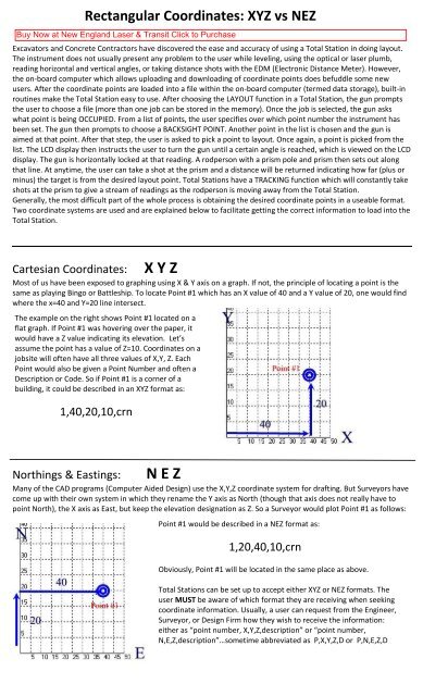
Cartesian <strong>Coordinates</strong>:<br />
X Y Z<br />
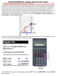
Most of us have been exposed to graphing using X & Y axis on a graph. If not, the principle of locating a point is the<br />
same as playing Bingo or Battleship. To locate Point #1 which has an X value of 40 and a Y value of 20, one would find<br />
where the x=40 and Y=20 line intersect.<br />
The example on the right shows Point #1 located on a<br />
flat graph. If Point #1 was hovering over the paper, it<br />
would have a Z value indicating its elevation. Let’s<br />
assume the point has a value of Z=10. <strong>Coordinates</strong> on a<br />
jobsite will often have all three values of X,Y, Z. Each<br />
Point would also be given a Point Number and often a<br />
Description or Code. So if Point #1 is a corner of a<br />
building, it could be described in an <strong>XYZ</strong> format as:<br />
1,40,20,10,crn<br />
Northings & Eastings:<br />
N E Z<br />
Many of the CAD programs (Computer Aided Design) use the X,Y,Z coordinate system for drafting. But Surveyors have<br />
come up with their own system in which they rename the Y axis as North (though that axis does not really have to<br />
point North), the X axis as East, but keep the elevation designation as Z. So a Surveyor would plot Point #1 as follows:<br />
Point #1 would be described in a <strong>NEZ</strong> format as:<br />
1,20,40,10,crn<br />
Obviously, Point #1 will be located in the same place as above.<br />
Total Stations can be set up to accept either <strong>XYZ</strong> or <strong>NEZ</strong> formats. The<br />
user MUST be aware of which format they are receiving when seeking<br />
coordinate information. Usually, a user can request from the Engineer,<br />
Surveyor, or Design Firm how they wish to receive the information:<br />
either as “point number, X,Y,Z,description” or “point number,<br />
N,E,Z,description”…sometime abbreviated as P,X,Y,Z,D or P,N,E,Z,D
The appearance of a Coordinate File:<br />
The following drawing is of a building with various points (#6 to #23) around the perimeter. Point #1 and #2 are<br />
Benchmarks set by the surveyor. To layout the building, the Total Station could be set up over Point #1 or Point #2,<br />
using the other Point as the BACKSIGHT. Then, any of the Point numbers could be chosen from a list and the LCD<br />
would instruct what angle to turn the gun and how far back to go to stake out the desired point.<br />
The list of points is as follows:<br />
PointNo. Northing(Y) Easting(X) Elev(Z) Description<br />
1 4013.632 4386.496 184.980 BM<br />
2 3855.198 4762.072 180.230 BM<br />
3 4461.772 4350.852 194.314 BM<br />
6 4585.957 4294.613 194.000 bc<br />
7 4466.020 4454.661 194.000 bface<br />
8 4346.083 4614.708 194.000 bface<br />
9 4226.147 4774.756 194.000 bface<br />
10 4106.210 4934.803 194.000 bface<br />
11 4034.248 5030.832 194.000 bc<br />
12 3954.224 4970.863 194.000 bc<br />
13 3978.211 4938.854 194.000 bc<br />
14 3954.204 4920.863 194.000 bc<br />
15 4014.173 4840.839 194.000 bc<br />
16 3966.158 4804.858 194.000 bc<br />
17 4026.127 4724.835 194.000 bc<br />
18 4002.120 4706.844 194.000 bc<br />
19 4373.923 4210.697 194.000 bc<br />
20 4453.947 4270.665 194.000 bc<br />
21 4489.928 4222.651 194.000 bc<br />
22 4253.987 4370.745 194.000 bface<br />
23 4134.050 4530.792 194.000 bface
If the data is sent to a user as an attachment to an email, opening the attached file would produce something<br />
resembling the following:<br />
1,4013.63187,4386.49622,184.98000,BM<br />
2,3855.19767,4762.07175,180.23000,BM<br />
3,4461.77249,4350.85211,194.31442,BM<br />
6,4585.95663,4294.61327,194.00000,bc<br />
7,4466.01993,4454.66073,194.00000,bface<br />
8,4346.08323,4614.70818,194.00000,bface<br />
9,4226.14653,4774.75563,194.00000,bface<br />
10,4106.20982,4934.80309,194.00000,bface<br />
11,4034.24780,5030.83156,194.00000,bc<br />
12,3954.22408,4970.86321,194.00000,bc<br />
13,3978.21142,4938.85372,194.00000,bc<br />
14,3954.20430,4920.86321,194.00000,bc<br />
15,4014.17265,4840.83948,194.00000,bc<br />
16,3966.15841,4804.85847,194.00000,bc<br />
17,4026.12676,4724.83475,194.00000,bc<br />
18,4002.11965,4706.84424,194.00000,bc<br />
19,4373.92342,4210.69713,194.00000,bc<br />
20,4453.94715,4270.66549,194.00000,bc<br />
21,4489.92816,4222.65125,194.00000,bc<br />
22,4253.98672,4370.74459,194.00000,bface<br />
23,4134.05002,4530.79204,194.00000,bface<br />
Most Total Station vendors provide free software to transfer coordinates back and forth from a computer. Some<br />
settings must be synchronized between the Total Station and the computer when first installing. But after the initial<br />
setup, users generally find the process problem-free.