GradeLight 2700 - New England Laser & Transit Company
GradeLight 2700 - New England Laser & Transit Company
GradeLight 2700 - New England Laser & Transit Company

Create successful ePaper yourself
Turn your PDF publications into a flip-book with our unique Google optimized e-Paper software.
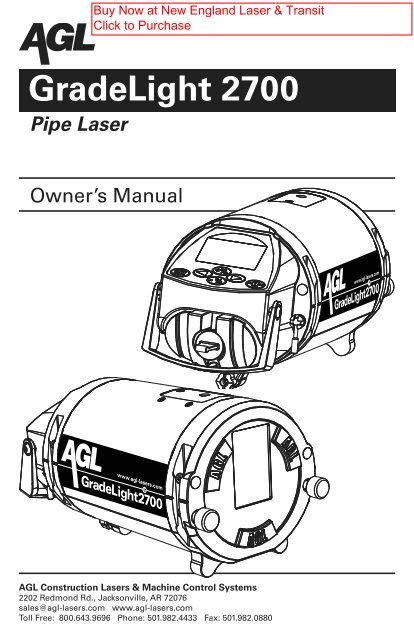
<strong>GradeLight</strong> <strong>2700</strong><br />
Pipe <strong>Laser</strong><br />
Owner’s Manual<br />
AGL Construction <strong>Laser</strong>s & Machine Control Systems<br />
2202 Redmond Rd., Jacksonville, AR 72076<br />
sales@agl-lasers.com www.agl-lasers.com<br />
Toll Free: 800.643.9696 Phone: 501.982.4433 Fax: 501.982.0880
CONTENTS<br />
General Information . . . . . . . . . . . . . . . . . . . . . . . . . . . . . . . . . . . . . . . . . . . . . . . . . . . . . . . . . 1-3<br />
Specifications ............................................................ 1<br />
<strong>Laser</strong> Overview . . . . . . . . . . . . . . . . . . . . . . . . . . . . . . . . . . . . . . . . . . . . . . . . . . . . . . . . . 2-3<br />
Power . . . . . . . . . . . . . . . . . . . . . . . . . . . . . . . . . . . . . . . . . . . . . . . . . . . . . . . . . . . . . . . . . . . . . 4<br />
Charging ................................................................ 4<br />
Removing the Battery Pack and Using Alkaline Batteries . . . . . . . . . . . . . . . . . . . . . . . . 4<br />
Operation ..................................................................5-9<br />
Pipe Laying Overview ..................................................... 5<br />
<strong>Laser</strong> Start-up ............................................................ 5<br />
Entering Grade ........................................................... 6<br />
Automatic Reset to Zero Grade ........................................... 6<br />
Remote Control and Line Adjustment (Azimuth) . . . . . . . . . . . . . . . . . . . . . . . . . . . . . . . 7<br />
Replacing Batteries in Remote ............................................ 8<br />
Adjustable Leg Set ........................................................ 8<br />
Using the Target .......................................................... 9<br />
Basic Set-up and Operation . . . . . . . . . . . . . . . . . . . . . . . . . . . . . . . . . . . . . . . . . . . . . . . . 9<br />
Applications ..............................................................10-16<br />
Elevation Transfer . . . . . . . . . . . . . . . . . . . . . . . . . . . . . . . . . . . . . . . . . . . . . . . . . . . . . . . 10<br />
Using an Automatic Level .............................................. 10<br />
Using the Special <strong>Transit</strong> and Rod Group .................................. 10<br />
Alignment Methods .......................................................11<br />
Manhole Mount with <strong>Transit</strong> ..............................................11<br />
Special <strong>Transit</strong> with Rod Group . . . . . . . . . . . . . . . . . . . . . . . . . . . . . . . . . . . . . . . . . . 12<br />
Stringline Method ..................................................... 12<br />
Plumb Bob Method .................................................... 12<br />
Set-up Methods ......................................................... 13<br />
Height Adjustable Legs ................................................. 13<br />
Manhole Base Set-up . . . . . . . . . . . . . . . . . . . . . . . . . . . . . . . . . . . . . . . . . . . . . . . . 13<br />
In-the-pipe Set-up ................................................... 13<br />
Invert Set-up . . . . . . . . . . . . . . . . . . . . . . . . . . . . . . . . . . . . . . . . . . . . . . . . . . . . . . . 14<br />
Open Cut Set-up . . . . . . . . . . . . . . . . . . . . . . . . . . . . . . . . . . . . . . . . . . . . . . . . . . . . 14<br />
Trivet . . . . . . . . . . . . . . . . . . . . . . . . . . . . . . . . . . . . . . . . . . . . . . . . . . . . . . . . . . . . . . . 15<br />
Manhole Base Set-up . . . . . . . . . . . . . . . . . . . . . . . . . . . . . . . . . . . . . . . . . . . . . . . . 15<br />
Rod and Crossbrace System . . . . . . . . . . . . . . . . . . . . . . . . . . . . . . . . . . . . . . . . . . . . 15<br />
Manhole Set-up ..................................................... 15<br />
Above Ground Set-up .................................................. 16<br />
Menu Options . . . . . . . . . . . . . . . . . . . . . . . . . . . . . . . . . . . . . . . . . . . . . . . . . . . . . . . . . . . . 17-18<br />
Information Available (including software version) . . . . . . . . . . . . . . . . . . . . . . . . . . . . 17<br />
Entering the Set-up Menu ................................................. 17<br />
Changing the Service Interval . . . . . . . . . . . . . . . . . . . . . . . . . . . . . . . . . . . . . . . . . . . . . 18<br />
Deleting CHECK CAL Reminder . . . . . . . . . . . . . . . . . . . . . . . . . . . . . . . . . . . . . . . . . . . . 18<br />
Using Your <strong>Company</strong> Information for the Start-up Screen . . . . . . . . . . . . . . . . . . . . . . 18<br />
Troubleshooting ...........................................................19-20<br />
Display Screen Explanations . . . . . . . . . . . . . . . . . . . . . . . . . . . . . . . . . . . . . . . . . . . . . . 19<br />
Using a Blower to Eliminate Refraction ...................................... 20<br />
Optional Equipment . . . . . . . . . . . . . . . . . . . . . . . . . . . . . . . . . . . . . . . . . . . . . . . . . . . . . . . . . 20<br />
Checking and Calibration . . . . . . . . . . . . . . . . . . . . . . . . . . . . . . . . . . . . . . . . . . . . . . . . . . . 21-23<br />
Safety, Care, and Handling . . . . . . . . . . . . . . . . . . . . . . . . . . . . . . . . . . . . . . . . . . . . . . . . . . . . 24<br />
Warranty ................................................................... 25<br />
Important:<br />
The operator of the <strong>GradeLight</strong> is expected to follow all operating instructions, periodically<br />
check the accuracy of the unit, and make checks on control as the work progresses. The<br />
manufacturer and its distributors assume no responsibility for improperly controlled work.
GENERAL INFORMATION<br />
The <strong>GradeLight</strong> pipe laser provides alignment and grade for installation of gravity flow sanitary<br />
and storm sewer pipelines, as well as for pipe jacking and tunneling.<br />
The <strong>GradeLight</strong> includes:<br />
• Infrared remote control<br />
• Adjustable leg set for multiple pipe sizes<br />
• Rechargeable Li-ion battery pack and spare alkaline battery compartment.<br />
Other features include a wide automatic self-leveling range, short length to fit tight inverts,<br />
and adjustable target with magnetic base (included in designated packages).<br />
Specifications<br />
<strong>GradeLight</strong><br />
Self-Leveling Range +45% to -15%<br />
Grade Range +40% to -10%<br />
Grade Entry Rolling counter or digit select<br />
Grade Display 0.001%<br />
Azimuth Range Total range: 20 ft. at 100 ft. (6m at 30m)<br />
Accuracy ± 1/16” at 100 ft.<br />
(± 5mm at 100m; ± 10 arc sec.; ± .005%)<br />
Cross Axis Leveling Manual<br />
Beam Type/Output Visible laser diode, 635nm, < 5mW, Class 3R<br />
Environmental IP68; nitrogen purged<br />
Power Supply 1) Rechargeable lithium ion battery pack<br />
2) 110/230V AC converter (charge and run simultaneously)<br />
3) Spare battery compartment for 4 D-cell alkaline batteries<br />
4) Optional 12V power cord<br />
Battery Life at 32° F / 0° C 40 hrs. Li-ion battery; 50 hrs. alkaline<br />
Charging Time 5 hrs. maximum<br />
Mounting 5/8 x 11 (female mounting thread)<br />
Operating Temperature -4° to 122° F (-20° to +50° C)<br />
Storage Temperature -40° to 140° F (-40° to +60° C)<br />
Dimensions Diameter: 5.5” (140mm) / Length:
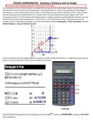
<strong>Laser</strong> Overview<br />
Stringline Hook/<br />
Accessory Mount<br />
Line<br />
Pivot Point<br />
Remote<br />
Reception<br />
Window (rear)<br />
LCD Display<br />
Keypad<br />
Handle<br />
Rechargeable<br />
Battery Pack<br />
Charging/Power<br />
Connector Cap<br />
Battery Pack<br />
Release Screw<br />
Toggle Screw to<br />
Tighten Leg<br />
Slot For<br />
Adjustable Leg<br />
5/8” x 11<br />
thread<br />
Leg Reference Lines<br />
Align To Marks on Legs<br />
Beam Output<br />
& Remote Reception<br />
Window<br />
Securing Knobs For<br />
Adjustable Legs<br />
Beam’s Horizontal<br />
Centerline<br />
Adjustable<br />
Leg Slot<br />
Feet For 6”<br />
(150mm) Pipe<br />
2
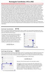
Keypad and LCD Overview<br />
Keypad Functions<br />
Power On/Off<br />
Enter digit select mode for grade<br />
Enter user settings menu<br />
Set azimuth line (left & right)<br />
Change digit positions when setting grade<br />
Set grade as rolling counter or digit select<br />
LCD Indications<br />
Line Adjustment Range Indicator<br />
Shows beam position relative<br />
to line adjustment range.<br />
Grade Entered<br />
Self-Leveling Status<br />
Battery Status<br />
Cross Axis Level Position<br />
Lock Status of <strong>Laser</strong> and Remote Keypad<br />
The display is backlit for 30 seconds when any button is pressed on the laser or remote.<br />
Safety Labels<br />
The <strong>GradeLight</strong> is a Class 3R laser, manufactured to comply with the international rules of<br />
safety IEC 60825-1, 2001. Although the power of the emission of the beam is less than 5mW in<br />
Class 3R, the following cautions are recommended:<br />
• Do not stare directly at the beam<br />
• Do not set up the laser at eye level<br />
Made in<br />
U.S.A<br />
3
POWER<br />
The <strong>GradeLight</strong> can be powered from the Li-ion rechargeable battery or the alkaline battery<br />
pack. It can also be used while charging -- from AC using the included converter, or from 12VDC<br />
using the optional power cable.<br />
Charging<br />
Charge before first use and when the battery symbol indicates low. The Li-ion battery can<br />
be charged in the unit, or removed and charged separately. This allows you to use alkaline<br />
batteries in the spare battery compartment on the job site while the battery is being charged<br />
elsewhere.<br />
The charging circuit is in the battery pack; the converter with cord allows charging from AC.<br />
Maximum charging time is 5 hours; a microcontroller prevents overcharging.<br />
To Charge the Battery:<br />
1) Connect the converter to the charging/power connector on the battery pack.<br />
2) Select the correct power plug adapter for your country and attach to the converter.<br />
Then plug the converter into a 110V or 220V AC outlet. A green LED indicates power; it<br />
is not a charging indicator.<br />
3) Always place the cap back onto the charging connector to protect from dirt.<br />
The laser can be used while charging, but the charging time may increase (up to 9 hours).<br />
• Do not charge in wet environments.<br />
• Do not use the charger with a generator.<br />
Connector for<br />
charging or for<br />
optional 12VDC<br />
power cord<br />
Battery Pack<br />
Release Screw<br />
Purge screw under black decal<br />
inside battery compartment<br />
DO NOT OPEN!<br />
If this screw is removed, the moisture-free<br />
nitrogen purge of the unit will be lost.<br />
Removing the Battery Pack and Using Alkaline Batteries<br />
The rechargeable battery pack can be replaced with the alkaline battery compartment or another<br />
Li-ion pack. Turn off the laser. Turn the release screw under the battery pack to remove it.<br />
If using the alkaline battery compartment, insert 4 “D” cells, noting the polarity indications on<br />
the outside of the case.<br />
NOTE: If the laser has been stored for a while, hold the ON button for at least 3<br />
seconds when starting the unit.<br />
4
OPERATION<br />
Pipe Laying Overview<br />
The three basic steps to successfully set up the <strong>GradeLight</strong> for laying pipe are:<br />
A. Dialing in the correct grade.<br />
B. Transferring the elevation to position the laser at the correct height.<br />
C. Aligning the laser beam to the forward manhole.<br />
Before Starting<br />
Attach the necessary mounting accessories, such as the handle/rod mount, trivet, legs, etc. to<br />
the unit. Power-up the unit and adjust the line control to the center of its range.<br />
At the beginning of a pipe laying job, consider the following tips for improved performance:<br />
• The <strong>GradeLight</strong> can be used to check the hubs prior to actually starting the work. This is an<br />
opportunity to catch potential errors before using the hubs as a reference to lay pipe.<br />
• Place grade rod or marker at the forward manhole for a place to align to.<br />
• When the last joint of pipe has been laid approaching a manhole, bring the <strong>GradeLight</strong><br />
forward so that as soon as the manhole is in place, you can set up again without delay.<br />
<strong>Laser</strong> Start-up<br />
Press On/Off button to power-up the laser.<br />
Check the following indications on the LCD:<br />
The start-up screen shows AGL.<br />
The battery capacity is displayed. Charge when there is one bar left.<br />
The laser automatically self-levels, and returns to the same grade and<br />
line settings as last used. If the LCD laser beam symbol is flashing, it’s<br />
still leveling. When the symbol is lit solid, the laser has leveled and is<br />
ready for use.<br />
Likewise, the beam emitted from the unit flashes until it has leveled.<br />
Cross axis<br />
not level<br />
Check the electronic cross axis vial. If it’s out-of-level, rotate the laser<br />
slightly to the left or right to level the cross axis.<br />
The bubble should be between the lines on the vial.<br />
Cross axis<br />
is level<br />
Center beam with:<br />
<strong>Laser</strong> keypad<br />
&<br />
or remote:<br />
Before each setup, center the beam using the laser keypad (press both<br />
arrows simultaneously for 2 seconds) or the remote (press CL button).<br />
5
Entering a Grade<br />
The grade range is from +40% to -10%. Grade can be set in increments as small as .001% using<br />
the digit select or rolling counter entry method.<br />
The display lights when entering grade. The LCD is color coded to match the grade entry<br />
button: green for positive grade and red for negative grade.<br />
Digit Select Grade Entry<br />
Press ENT.<br />
The first digit flashes.<br />
Select positive or negative grade. The first digit will continue to<br />
flash. To the left of the decimal is a whole unit of per cent grade; to<br />
the right of the decimal are tenths, hundredths, and thousandths.<br />
Change the value of the first digit with the grade buttons (+ to<br />
increase, — to decrease). For large changes hold the button.<br />
Increase Decrease<br />
Use the azimuth left or right arrows to move through the digits and<br />
to choose the next digit to be changed. The digit you’re working<br />
with will flash like a computer cursor. Use the + and — buttons<br />
again to change the value.<br />
After the desired digits have been chosen, press ENT to save, and<br />
begin the grade that’s been set.<br />
The LCD beam symbol flashes until the grade setting is reached.<br />
Rolling Counter Grade Entry<br />
For a positive grade, hold the + button for 15 seconds or more. After you release, it will automatically<br />
increase in grade until you push either the + or — button again to stop.<br />
For a negative grade, hold the — button as described above.<br />
Automatic Reset to Zero Grade<br />
Press both the + and — buttons simultaneously to automatically set the grade back to 0.000%.<br />
&<br />
6
Remote Control Overview<br />
The remote is used primarily to move the beam left or right, within the azimuth range, and<br />
to put the laser in standby or locked modes. Since it’s an infrared line-of-sight device, there<br />
should be no obstructions between it and the laser. It can be pointed at either the front side<br />
(through the pipe) or the back side of the laser.<br />
Infrared output:<br />
aim at capture<br />
window of laser<br />
LED flashes when any<br />
button is pressed.<br />
-- Green: normal<br />
-- Red: low remote battery<br />
Remote Keypad Functions<br />
Compartment for<br />
3 AA batteries<br />
(back side)<br />
Standby Mode<br />
• Press and hold 2 seconds. This puts laser in standby mode to save<br />
battery life during breaks. LCD on laser will show sleep symbol.<br />
• Press again to return to normal operation. All settings are retained.<br />
Reset Line to Center<br />
Hold 2 seconds, and laser beam automatically moves back to center<br />
azimuth position.<br />
Line Adjustment<br />
(left and right azimuth control)<br />
When using remote from the target side, beam moves in the direction<br />
of the arrows. If using remote from laser keypad side, beam moves in<br />
the opposite direction.<br />
Activates Lock Function<br />
All buttons on the remote and laser are blocked, preventing unintentional<br />
changes when the laser is in use. LCD on laser shows a lock<br />
symbol. To deactivate: Press the lock button again.<br />
LED for Line Pivot Point<br />
Press to turn on LED on top of laser, which is used for alignment outside<br />
of the manhole. Automatic shut-off after 1 minute.<br />
Line Adjustment<br />
The laser beam can be aligned to the target using the left and right line adjustment. The<br />
azimuth indicator on the LCD shows the beam position in the adjustment range. Before each<br />
setup, center the beam to allow maximum adjustment in each direction. The total range of<br />
movement is 20’ at 100’ (6m at 30m).<br />
To Move the Beam<br />
Use arrows on the laser keypad or remote. Movement will start slow and speed up as long as<br />
the button is pressed.<br />
7
To Automatically Center the Beam<br />
On laser keypad, press simultaneously<br />
On remote, press<br />
&<br />
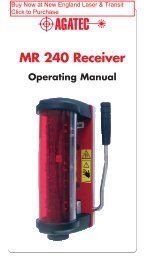
Replacing the Batteries of the Remote Control<br />
The LED on the remote will flash red when the batteries are low. To change the batteries:<br />
1. Open the housing by removing the 6 screws.<br />
2. Take the back case off and replace the<br />
batteries, matching the polarity indications.<br />
Use AA alkaline batteries of the same type;<br />
do not mix new and old batteries, as their<br />
lifetime will decrease.<br />
3. Before closing, check that the seal is free of<br />
dirt, to ensure it remains waterproof.<br />
4. Close the housing and tighten the 6 screws<br />
so it’s watertight.<br />
Adjustable Leg Set<br />
One leg set covers multiple pipe sizes. The adjustable “slide leg system” allows the user to set<br />
centerline in 8”, 10” and 12” pipe (200, 250, and 300mm with the metric leg set). The legs can<br />
also be adjusted to non-standard heights.<br />
The three-leg design provides stability when setting up on uneven, rough surfaces.<br />
To attach legs:<br />
1. Use curved centerline leg at rear (keypad end) and<br />
two side legs at front.<br />
2. Slide each leg into the slot on the housing.<br />
3. Match the red reference marks on the housing to red<br />
mark on leg. There are 3 reference marks: 8”, 10”, and 12”<br />
(200, 250, and 300mm).<br />
4. Tighten front legs with thumb screws, and single leg<br />
with toggle screw.<br />
Note: The legs will then be aligned for use in a pipe’s curved surface, where the two side legs<br />
need to be shorter than the center leg. If you are setting up on a flat surface, adjust the legs<br />
differently to level the unit.<br />
For 6” pipe (150mm), use the unit’s built-in feet. A long leg set is available as an optional accessory<br />
for 15” to 24” pipe (with a metric leg set for 375 to 600mm pipe).<br />
8
Using the Target<br />
The target can be used for multiple pipe sizes. It features<br />
a unique design: the target panel is mounted at the front<br />
of the base, not in the center. This allows you to view<br />
it easier at the front of the pipe. It also has a magnetic<br />
base for attaching to trench box side wall after pipe setting<br />
for better airflow, to minimize refraction.<br />
Alignment notch for 6”, 8”, or 10” pipe<br />
Alignment notch for 150, 200, or 250mm pipe<br />
Level vial<br />
Magnetic attachment (underneath)<br />
Basic Set-up And Operation<br />
The steps noted below are illustrated in previous sections. See next section for specific applications.<br />
1. Attach any mounting accessories to the unit, such as the legs, trivet, handle/rod mount,<br />
etc. Place it in the manhole or pipe at the proper offset and elevation.<br />
2. Power-up the laser. Swivel it left or right so that the cross axis is level. Check the vial on<br />
the LCD (see p. 3). Set the desired grade.<br />
3. Adjust the target plate to the correct pipe diameter. Place the target in the opposite end<br />
of the pipe and level it using the vial.<br />
4. Adjust line to the center of its range with the remote by pressing the centerline button<br />
or by pressing both line adjust buttons simultaneously. Use the remote to align the<br />
beam to the target.<br />
5. Lift pipe up or down until beam is in the middle of the target bull’s-eye; the pipe is<br />
then on line and at the desired slope.<br />
9
APPLICATIONS<br />
Transfer of Elevation<br />
Using an Automatic Level<br />
1. Mount the level on a tripod outside the manhole<br />
or open cut. Adjust it to level and point at the<br />
manhole hub. Take a reading from a rod held at<br />
the hub. This reading is sometimes called the<br />
“back-sight” reading. (Figure A)<br />
Figure A<br />
HI<br />
1st reading<br />
2nd Reading<br />
Elevation of<br />
Manhole Base<br />
ROD<br />
HUB<br />
2. Now take a rod reading at the manhole center. If<br />
a manhole is in place, read the elevation of the<br />
base. In an open cut it is necessary to place an<br />
object in the cut which can be used as a reference.<br />
A brick, stone, or board placed at manhole<br />
center will work for marking a reference elevation,<br />
and as a starting point for the placement of<br />
the laser or the trivet.<br />
Using the Special <strong>Transit</strong> and Rod Group<br />
This is an ideal method to use when the offset hub<br />
is too far from the manhole center to transfer<br />
elevation with a batter-board or other means.<br />
The Special <strong>Transit</strong> is set up using the Rod and<br />
Crossbrace System. (Figure B)<br />
1. Mount the Special <strong>Transit</strong> on the calibrated rod<br />
and point it to the manhole hub. The top edge<br />
of the transit mounting bracket is the elevation<br />
reference and is the same as the horizontal<br />
crosshair (centerline) of the transit.<br />
2. Level the transit using the adjust knob and the<br />
level vial. Use the forward marker knob to adjust<br />
the transit so that it is pointed exactly to an<br />
engineer’s rule or calibrated rod section held at<br />
the manhole hub.<br />
3. After reading the engineer’s rule or calibrated<br />
rod, measure down from the top edge of the<br />
transit mounting bracket (transit centerline) to<br />
the correct invert elevation.<br />
Figure B<br />
10
Alignment Methods<br />
After the laser is set up at the correct elevation and the<br />
correct grade is entered, the last step is to align the beam<br />
to the forward manhole using one of these methods:<br />
1) Manhole Mount with <strong>Transit</strong><br />
2) Special <strong>Transit</strong> and Rod Group<br />
3) Stringline<br />
4) Plumb Bob<br />
Manhole <strong>Transit</strong> Method<br />
This method can be used with the Special <strong>Transit</strong> or any<br />
standard transit (ideally one that has a back sight – flop<br />
– capability). Use the Manhole <strong>Transit</strong> Clamp system to<br />
support the transit. The laser is set up in the manhole using<br />
leg sets, or the trivet.<br />
1. Secure the Clamp Body and Mast (Figure C). Position<br />
the clamp (1) over the top edge of the manhole so the<br />
mast (2) is plumb enough to easily level the transit<br />
when mounted. Tighten the clamp screw (3), until the<br />
clamp points are firmly embedded in the sides of the<br />
manhole. The mast can be further adjusted to plumb<br />
using the lever (4) locking the mast pivot.<br />
Secure the Arm - Slide the arm clamp support (5) and<br />
the arm clamp (6) over the mast and secure. Insert the<br />
arm (7) into the clamp. The clamp allows complete<br />
flexibility to raise, extend, and position the arm so the<br />
transit mount (8) is over the manhole center. The transit<br />
mount is a 5/8 x 11 male attachment for mounting a<br />
standard transit. The AGL Special <strong>Transit</strong> is mounted,<br />
using an adapter assembly.<br />
Aligning the beam with the AGL Special <strong>Transit</strong><br />
2. Mount the Special <strong>Transit</strong> and adapter to the mount at the end of the arm. Adjust the arm so the<br />
transit is roughly over pipe centerline and in line with the laser (Figure D). Adjust the vertical<br />
crosshair exactly to the forward manhole marker using the forward marker knob.<br />
3. Align <strong>Transit</strong> to <strong>Laser</strong> - Tilt the transit down and sight the line pivot green LED. On the transit,<br />
use the laser centerline knob to adjust the vertical crosshair until aligned exactly with the green<br />
LED. Repeat steps 2 and 3 until the vertical crosshair is on both the forward manhole marker<br />
and the green LED on the unit.<br />
4. Align the <strong>Laser</strong> Beam to the <strong>Transit</strong> - Place a target in the ditch approximately 15’ (5m) in front<br />
of the laser. Looking through the transit at the target, adjust the beam left or right using the<br />
alignment buttons on the remote control until exactly centered on the vertical crosshair. You<br />
should then be able to swing the transit from the beam, to the green LED, and to the forward<br />
manhole marker, with each being aligned to the crosshair (Figure E). Repeat steps 2, 3 and 4 if<br />
necessary. When all three are accurately aligned, pipe laying can proceed.<br />
5<br />
2<br />
5<br />
4<br />
1<br />
3<br />
6<br />
7<br />
8<br />
Figure C<br />
Figure D<br />
Figure E<br />
2<br />
3 4<br />
11
Aligning the beam with a standard transit<br />
Align the <strong>Transit</strong> over the Instrument - Mount the standard<br />
transit to the transit mount at the end of the arm. Using a<br />
plumb bob, adjust the arm so the transit is directly over the<br />
centerline of pipe. Level the transit. Position the laser so the<br />
line pivot LED is exactly under the plumb point.<br />
Align the <strong>Transit</strong> to Forward Manhole - Pivot the transit until<br />
the vertical crosshair splits the forward manhole marker.<br />
Align to the Beam using step 4 above.<br />
Special <strong>Transit</strong> Method<br />
This method uses the Rod and Crossbrace system<br />
The laser is mounted with the Handle/Rod Mount (Fig F).<br />
1. Mount the Special <strong>Transit</strong> - With the rod plumbed, and laser<br />
leveled, mount the Special <strong>Transit</strong> on the rod. Position the<br />
transit where it is possible to see the forward manhole<br />
marker, yet as low as possible on the rod. Secure the rod<br />
mounting bracket with the secure knob.<br />
2. Align <strong>Transit</strong> to Forward Manhole Marker - Use the forward marker knob to adjust the vertical<br />
crosshair until it is aligned with the forward manhole marker.<br />
3. Align <strong>Transit</strong> to <strong>Laser</strong> - Tilt the transit down and sight on the green LED. On the transit, use the<br />
laser centerline knob to adjust the vertical crosshair until it is exactly aligned with the green<br />
LED on the laser. Repeat steps 2 and 3 until the crosshair is on the forward manhole marker<br />
and the green LED.<br />
4. Align the <strong>Laser</strong> Beam to the <strong>Transit</strong> - Place a target in the ditch approximately 15’ (5m) out in<br />
front of the laser. Tilt the transit down to view the target. Adjust the beam left or right using<br />
the line adjustment buttons on the remote until the beam is exactly centered on the vertical<br />
crosshair.<br />
You should be able to swing the transit from the beam, to the green LED, or forward manhole<br />
marker, with each being exactly aligned to the crosshair. Repeat steps 2, 3, and 4 if necessary.<br />
When all three are accurately aligned, pipe laying can proceed.<br />
Stringline Method<br />
The stringline provides a quick, easy method of beam alignment. Place a target in the ditch<br />
approximately 50’ (15m) out from the laser. Attach a string to the eyelet hook, located on top of<br />
the <strong>GradeLight</strong> and keeping it plumb, hold it taut, vertically<br />
above the unit (Figure G).<br />
Stand behind the string and visually center it on the forward<br />
manhole. Lower your gaze to the target and use the remote<br />
control to adjust the beam left or right until exactly centered<br />
behind the stringline.<br />
When you can see the stringline centered on the forward<br />
manhole marker and on the beam in the ditch, alignment is<br />
complete.<br />
Plumb Bob Method<br />
This method of alignment can be used if the cut is not too<br />
deep and the wind is relatively calm. The laser must be set up<br />
at the correct elevation and exactly on pipe centerline. Place a<br />
target in the ditch approximately 50’ (15m) out from the laser.<br />
Measure over from an offset hub to the pipe center line and<br />
drop a plumb bob down to the target.<br />
Mark where the plumb bob strikes the target and adjust the<br />
beam left or right until it is centered on the plumb mark.<br />
12<br />
Forward<br />
Manhole<br />
Marker<br />
Figure G<br />
Target<br />
Figure F<br />
Stringline<br />
Held<br />
Vertical<br />
Stringline<br />
Hook
Set-up Methods<br />
These instructions describe four ways to<br />
set up: height adjustable legs, trivet, rod<br />
and crossbrace, or above ground on a<br />
tripod.<br />
Height Adjustable Legs<br />
The adjustable legs can be used to set up<br />
in a manhole base, pipe, invert, or open<br />
cut.<br />
Manhole Base Set-up<br />
1. Prepare laser for use: Attach leg set<br />
with centerline leg at front and two<br />
side legs at rear. Apply power, center<br />
the line adjustment, and enter the<br />
desired grade.<br />
2. Transfer elevation from the hub to the manhole base.<br />
3. Set the front (centerline) leg to the desired height: After determining the desired beam<br />
height above the manhole base, adjust the front leg so the beam will be projected at that<br />
height.<br />
4. Set the unit in place: Position the point of the front leg on pipe centerline, 2” (5 cm) in front<br />
of the manhole center, toward the pipe being laid for accurate alignment. (Figure H)<br />
5. Roughly level the instrument by loosening the rear leg knobs and sliding the unit up or<br />
down, then tighten.<br />
6. Align laser to the forward manhole (see previous section on “Alignment”).<br />
7. Recheck for level and accurate grade setting and proceed to lay pipe.<br />
In-the-pipe Set-up<br />
When setting up in-the-pipe, be sure the joint of pipe used for the set-up is accurately placed<br />
for line and elevation.<br />
Set-up in 6”(150mm) pipe:<br />
1. Remove the handle/rod mount and legs, if attached. Apply power, center the line adjustment,<br />
and enter the desired grade.<br />
2. Slide the unit into the pipe. It should rest on the three fixed short leg points of the housing.<br />
Rough level the unit in the cross axis direction if necessary, using the lighted cross-axis level<br />
vial on the rear control panel.<br />
3. Align the beam to the forward manhole using the remote line control, or the line adjustment<br />
buttons on the unit.<br />
Set-up in 8”, 10”(200mm, 250mm) and larger pipe:<br />
1. Remove the handle/rod mount if attached. Apply power, center the line adjustment, and<br />
enter desired grade.<br />
2. Attach the leg set with two side legs at the front and the centerline leg at the rear. Set all<br />
three legs so the appropriate pipe size mark is aligned with the centerline-of-beam mark<br />
beside each leg slot.<br />
3. Slide the unit into pipe and rough level in the cross-axis direction using the cross-axis level<br />
vial on the control panel.<br />
4. Align the beam to the forward manhole using the remote line control, or the line adjustment<br />
buttons on the unit.<br />
5. The beam should be projecting at pipe centerline. Allow the unit to self-level, then lay pipe.<br />
NOTE: If you prefer, you can use the 6” (150mm) for ALL in pipe set-ups as long as you<br />
remember to reference the lower offset to the gravel and trench excavation depth. What<br />
is important is that the beam elevation from the invert and the target centerline elevation<br />
from the invert is the same.<br />
Pipe<br />
Manhole<br />
Center<br />
<strong>Laser</strong><br />
2"<br />
5cm<br />
Place Front<br />
Leg Point here<br />
Direction<br />
Figure H<br />
13
Invert Set-up<br />
Position the legs the same as you would if setting up<br />
inside the pipe. Place the laser in the invert and complete<br />
the set-up as shown in the Manhole Base Set-up in the<br />
previous section.<br />
Open Cut Set-up<br />
When using the height adjustable legs in an open cut,<br />
a stable base such as a concrete block, brick, or board<br />
must be placed in the cut at the manhole center and<br />
marked. This is best done when transferring elevation<br />
(see page 10).<br />
Place one of the blocks at manhole center. The front<br />
leg will be positioned on this block 2” (5 cm) in front of<br />
the center mark for critical high accuracy, or on top of<br />
a centerline hub for most applications. Place the other<br />
blocks, etc. so that they provide support for the rear legs<br />
(Figure I).<br />
Set up the unit for laying pipe as described in Manhole<br />
Base Setup in the previous section.<br />
Invert Peg Set-up (Open Cut)<br />
This method is commonly used in open ditches. The cut<br />
should be excavated approximately 6” (150mm) below<br />
invert elevation. (Figure I)<br />
1. Place a stake at the invert elevation.<br />
2. Prepare the laser for use: apply power, center the line<br />
adjust range, and enter the desired grade. Attach the<br />
leg set with the centerline leg at the front and two side<br />
legs at the rear.<br />
3. Set the front centerline leg for correct pipe size using<br />
the marks on the legs.<br />
4. Place the laser in the trench with the single front leg<br />
on the stake (peg). Rest the rear legs on blocks, bricks,<br />
or the ground.<br />
6. Align the beam to the forward manhole.<br />
7. Recheck for accurate grade settings and a level unit.<br />
Proceed to lay pipe.<br />
NOTE: In open cut set-ups the optional long leg set is<br />
usually required.<br />
Figure I<br />
Beam Centerline<br />
Invert Elevation<br />
Manhole<br />
14
Trivet<br />
Manhole Base Set-up<br />
1. Prepare the laser for use: Attach handle/rod mount,<br />
apply power, center the line adjustment, and enter<br />
desired grade. Mount the height adjustable rod (center<br />
the rod height in its adjustment range) to the trivet.<br />
(Figure J)<br />
2. Transfer elevation from the hub to the manhole base.<br />
3. Position the trivet over the manhole center: Place the<br />
front leg of the trivet on the centerline-of-pipe, 5” (13<br />
cm) in front of the manhole center mark.<br />
4. Secure the laser to the rod at the approximate<br />
elevation where the pipe centerline will be.<br />
5. Allow the unit to self-level.<br />
6. Use the height adjustable rod to precisely adjust the<br />
beam elevation. The centerline of beam marks on the<br />
side of the unit are also convenient for establishing<br />
elevation.<br />
7. Align the beam to the forward manhole. Recheck all<br />
the alignment steps to assure accuracy. Check that the<br />
unit is level with an accurate grade setting. Proceed to<br />
lay pipe.<br />
Figure J<br />
Rod and Crossbrace System<br />
1. Prepare the laser for use: Attach handle/rod mount, apply power, and center the line<br />
adjustment.<br />
2. Mount crossbrace inside the manhole, perpendicular to the centerline of pipe being laid.<br />
Use the level vial on the crossbrace to position it level. Holding the two points firmly against<br />
the manhole wall, extend and tighten the adjusting screw point against the opposite wall.<br />
Tighten until the crossbrace is solid, with the points planted firmly into the concrete.<br />
3. Secure alignment element to the crossbrace using the secure knob. Hang the alignment<br />
element on the crossbrace so that the line control and front secure knobs face the forward<br />
manhole. Measure manhole width where the crossbrace is mounted and use the center<br />
as reference. Place the right edge of the alignment element 2 1/4” (57mm) left of manhole<br />
center.<br />
4. Slide the calibrated rod with the point attached through the alignment element, plumb it<br />
using a hand level, then tighten the secure knob.<br />
NOTE: Pull up on the crossbrace as you tighten the alignment element, then release after it<br />
is tight. This places downward tension on the rod and increases its stability.<br />
5. Establish invert elevation and beam height (see previous section on “Transfer of Elevation -<br />
Special <strong>Transit</strong> Method”).<br />
6. Secure the laser to the rod at the correct elevation and allow the unit to self-level.<br />
7. Align beam to the forward manhole (see previous section on “Alignment – Special <strong>Transit</strong><br />
Method”). Recheck alignment steps to assure accuracy. Check for level unit and accurate<br />
grade setting, then proceed to lay pipe.<br />
15
Above Ground Set-up<br />
1. Prepare laser for use: mount the sighting scope and<br />
attach to a 5/8”x11 dome head tripod. Center the line<br />
adjustment, and set grade at exactly zero.<br />
2. Measure over from an offset hub and position the<br />
tripod directly over the pipe centerline trying to keep<br />
the top of the tripod as level as possible. Use a plumb<br />
bob if needed. Spread the tripod legs and plant them<br />
firmly into the ground to provide a stable base.<br />
3. Allow the laser to self-level.<br />
4. Slightly loosen the tripod securing knob and turn the<br />
laser and scope to the rod held at the manhole hub.<br />
Tighten the knob, then use the line adjust buttons<br />
to align the beam exactly to the rod. Take a reading<br />
(sometimes called “back-sight” elevation) at the beam<br />
centerline. This measurement plus the “cut” at that<br />
hub will be the HI (instrument height) above the invert.<br />
If the grade pole is used on top of the pipe, allow for<br />
the height difference when setting up (Figure K). Set<br />
the centerline of the above ground target at the correct<br />
distance to the invert OR to the top of the pipe.<br />
5. Enter the desired percent grade.<br />
6. Loosen the tripod securing knob, roughly aim the<br />
laser to the forward marker at the next manhole and<br />
tighten. Depending on the package used, use the red<br />
filter sighting scope to find the beam on a target at the<br />
forward marker and use the line adjust buttons to get<br />
to centerline, or if using the remote control, walk the<br />
beam to the forward marker and use the remote to put<br />
the beam on the centerline.<br />
7. Dial in the grade on the unit and lay pipe.<br />
Figure K<br />
ABOVE<br />
GROUND<br />
TARGET<br />
ROD READING<br />
(Backsight Elevation)<br />
HUB<br />
ELEVATION<br />
CUT TO<br />
INVERT<br />
16
MENU OPTIONS<br />
The user and service personnel can access information through the Set Up Mode. These are<br />
the menu selections shown in Step 3 in the next section:<br />
INFO<br />
SETTINGS<br />
Shows serial number, software version, number of working hours, and<br />
service information. There are no values that can be changed.<br />
Three settings can be changed; see instructions later in this section:<br />
• The service interval reminder (CHECK CAL) can be changed from the<br />
default of 2000 hrs. to 500 or 1000 hrs.<br />
• When the reminder appears on the screen, it can be turned off<br />
(and the counter reset to 0 hours).<br />
• The start-up screen can be changed from “AGL” to your<br />
company information.<br />
CALIBRATION<br />
SERVICE<br />
See instructions for “Adjusting Level Accuracy” later in the manual.<br />
A password is needed by service personnel to access this area.<br />
Entering the Set Up Menu<br />
1. Turn the laser off, and then turn the laser on<br />
again.<br />
&<br />
2. When the AGL start-up screen is displayed,<br />
press the + and ENT buttons simultaneously. Hold<br />
until the Set Up screen appears (after the Battery<br />
Check).<br />
3. The cursor and highlighted text indicate the<br />
active menu step.<br />
Move UP the Menu<br />
Move DOWN the Menu<br />
Use the + or – buttons to move up or down the<br />
menu. When you reach the desired step, such as<br />
CALIBRATION, press ENT.<br />
When you want to leave a menu section, move the<br />
cursor to EXIT and press ENT.<br />
17
Changing the Service Interval<br />
You can change the interval for the service reminder from the default of 2000 working hrs. to<br />
500 or 1000:<br />
1. Enter the Set Up mode following Steps 1-3 of “Set Up Menu” in previous section.<br />
2. Move down the menu to SETTINGS and press ENT.<br />
3. Go to CAL CHECK TIME and press ENT.<br />
4. In this menu, you can select 500, 1000, or 2000 hrs. The time currently selected will say<br />
CAL TIME = XXXX HRS.<br />
5. Use the + or – buttons to select the desired time and press ENT.<br />
6. Go down to EXIT and press ENT. Repeat to leave the Set Up menu.<br />
Deleting the CHECK CAL Reminder<br />
Once the laser reaches the working hours chosen, a reminder will appear on the screen:<br />
CHECK CAL. You should be checking the calibration regularly. This is a reminder of operating<br />
time intervals. The reminder will appear every time you turn on the laser until you reset the<br />
service interval:<br />
1. Enter the Set Up mode following Steps 1-3 of “Set Up Menu” in previous section.<br />
2. Move down the menu to SETTINGS and press ENT.<br />
3. Go to CAL CLEAR and press ENT.<br />
4. TIMER = 0 will be displayed, indicating that the timer is back to zero.<br />
6. Go down to EXIT and press ENT. Repeat to leave the Set Up menu.<br />
Changing AGL Start-up Screen To Your <strong>Company</strong> Information<br />
If a non-AGL name is already being used, follow Steps 1-2 and 5-8 to change to a different name.<br />
1. Enter the Set Up mode following Steps 1-3 of “Set Up Menu” in previous section.<br />
2. Move down the menu to SETTINGS and press ENT.<br />
3. Go to CUST ID and press ENT.<br />
4. The 1st line will say LOGO = AGL. Move to the 2nd line which says CUST ID and<br />
press ENT. It will then display LOGO = CUSTOM ID.<br />
5. Go to BUILD CUST ID and press ENT.<br />
6. Use the arrow keys to move the cursor to the left and right.<br />
• To move the cursor to the 2nd line, move it to the far right of the 1st line and press<br />
the right arrow one more time. This will take you to the 1st character of the 2nd line.<br />
• You may use this second line for a phone number, abbreviated address, or e-mail.<br />
• To move back to the 1st line, either press the left arrow or move the cursor all the<br />
way to the right and press the right arrow one more time.<br />
7. Texting: once the cursor is where you want it, press the up or down button to scroll<br />
through the alphabet and numbers. When the letter you want is displayed, move the<br />
cursor to the next character. When you are done, press ENT to save it.<br />
8. Go down to EXIT and press ENT. Repeat to leave the Set Up menu.<br />
18
TROUBLESHOOTING<br />
Indication on LCD <strong>Laser</strong> Beam Reason Remedy<br />
Blinking<br />
Flashes evenly <strong>Laser</strong> is leveling Wait until self-leveling<br />
___ ___ ___ is completed.<br />
Pulses in Self-leveling Change position of laser in<br />
2 short flashes range is exceeded direction arrows indicate.<br />
- - - - - - When it’s within the<br />
self-leveling range, the<br />
warning will disappear and<br />
self-leveling will begin.<br />
Pulses in Cross axis is Rotate laser slightly to the<br />
2 short flashes not level left or right until bubble<br />
- - - - - - is between the lines on<br />
electronic vial.<br />
CHECK CAL Reminder that laser The laser can continue to be<br />
has reached used. You should be<br />
2000 hrs. checking the calibration on<br />
of use, or the a regular basis. This<br />
interval set is a reminder of operating<br />
by the user. time intervals. To delete this<br />
message, see “Set Up<br />
Mode Menu Options.”<br />
ERROR 0 No beam; error Data error Turn laser on again.<br />
turns unit off<br />
Check calibration. If the<br />
automatically<br />
message appears again,<br />
contact an authorized<br />
service center.<br />
<strong>Laser</strong> doesn’t power-up<br />
• Check battery<br />
• Hold the ON button for at least 3 seconds (if you haven’t used the laser in a while).<br />
Loss of distance<br />
• Check window on laser where beam is emitted and clean if needed<br />
Dancing laser spot<br />
• Use a blower to reduce refraction and scintillation problems<br />
Remote control not working<br />
• At longer distances, ensure the remote is in the “line of sight” of the laser. Point remote<br />
directly at reception window on <strong>GradeLight</strong> and remove any obstacles between remote<br />
and laser.<br />
• Check and replace batteries<br />
• Operating range is reduced due to rain or fog – use at closer range.<br />
• Operating range is reduced due to dirt on the reception window of the <strong>GradeLight</strong> –<br />
clean with a soft cloth.<br />
19
Using a Blower to Eliminate Refraction<br />
Certain conditions can cause refraction and<br />
scintillation to occur inside the pipe, with the<br />
laser dot appearing to be dancing all around the<br />
target.<br />
The laser light passes through a medium – air.<br />
Anything that disturbs the air will cause the light<br />
to scintillate (dance). The two main causes of<br />
disturbed air are temperature difference and glue<br />
used to connect the pipes.<br />
Before being put in the ground, the pipe lies<br />
around the job site in the sun and heat of the day.<br />
The pipe is placed into the ground, which is much<br />
cooler than the road or dirt surface. The pipe has<br />
heated air and will continue to heat the air until it<br />
cools off. The turbulent flowing air in the pipe will<br />
cause the laser dot to dance.<br />
AGL Blower<br />
1-08915<br />
12VDC<br />
A solution is to use a blower to move cool air through the pipe. Set the blower at about 5 mph.<br />
A dangling dollar bill placed at the outflow end of the pipe will be at a 45° angle in 5 mile per<br />
hour of flow – sufficient to cool the pipe in about 20 minutes.<br />
Glue, as it dries, gives off vapors. These vapors are a different density, and possibly different<br />
temperature, than the air. This also causes the dancing dot. You will need to wait until the glue<br />
is dried enough so that the laser dot is fixed for a good reading.<br />
OPTIONAL EQUIPMENT<br />
Blower for Refraction Control<br />
Minimizes laser drift for long pipe runs where there is more than a 20º F temperature difference<br />
between the trench top and bottom. P/N 1-08915<br />
Target Panel<br />
For 12” and 15” (300-400mm) pipe. Can be used with standard frame. P/N 1-11254<br />
Large Target Assembly<br />
For 15” (375mm) and larger pipe. P/N 1-11217<br />
Tall Leg Set<br />
For 15” to 24” pipe:<br />
Order 2 side legs (9-09622) and 1 center leg (9-09623).<br />
Metric, for 375-600mm pipe:<br />
Order 2 side legs (9-09606) and 1 center leg (9-09607).<br />
Optical Instruments for Checking Elevation<br />
Digital Level and Bar Code Rod<br />
One push of a button provides digital elevation and distance. Eliminates rod reading errors.<br />
P/N 1-16612<br />
AL26-C Automatic Level<br />
High accuracy, wire hung magnetic compensator with 26X magnification. P/N 1-16613<br />
20
CHECKING & CALIBRATION<br />
THIS CHAPTER IS VERY IMPORTANT. Here are a few simple instructions to check your<br />
<strong>GradeLight</strong> for calibration. Remember that the laser is a precision instrument and that it is<br />
important that you keep it calibrated and in proper condition. The accuracy of your work<br />
is completely your responsibility and you should check your instrument before beginning<br />
each job, and especially after the instrument has taken a sharp jolt or been dropped, or<br />
when temperature changes greater than 50 degrees F (28 degrees C) have occurred.<br />
Checking Level Accuracy<br />
Select a reasonably level area. Set up the <strong>GradeLight</strong> on a stable surface. The cross axis vial<br />
should be centered and the legs adjusted so the unit is level.<br />
It will be easier to adjust the laser to strike stake B in Figure 1 if you use the single centerline<br />
leg in the front (beam side) or if you use a trivet with height adjustable rod.<br />
After the unit has self-leveled, set the grade at 0.000%.<br />
Fig. 1<br />
Stake<br />
A<br />
Stake<br />
B<br />
1. Establish two benchmarks:<br />
Figure 1: Drive two stakes (A & B) in line with<br />
the laser beam, but low enough for the beam<br />
to pass over both stakes. Stake A should<br />
be about 1’ (.3m) from the unit, and stake B<br />
about 100’ (30m) away.<br />
Fig. 2<br />
100’<br />
2. Check the instrument:<br />
A. Figure 2: Place a short 2x4 or something<br />
similar on stake A, and mark where the center<br />
of the beam strikes. Call this mark A1.<br />
B. Place the same 2x4 on stake B and again<br />
mark where the center of the beam strikes.<br />
Call this mark B.<br />
A1<br />
Stake<br />
A<br />
B<br />
Stake<br />
B<br />
3. Move the laser to the far side of stake B<br />
(Figure 3) so the beam will cross over both<br />
stakes as before, but in reverse order.<br />
A. Be sure the height of the unit is set so<br />
that when the 2x4 is placed on stake B,<br />
the beam will strike at mark B.<br />
B. Now place the 2x4 on stake A. Make a<br />
second mark (A2) where the center of<br />
the beam strikes.<br />
Fig. 3<br />
At 100 ft., the marks should be no more than<br />
1/8” apart (at 30m, no more than 3 mm apart).<br />
This is within the stated accuracy of ± 1/16”<br />
at 100 ft.<br />
A1<br />
A2<br />
Stake<br />
A<br />
B<br />
Stake<br />
B<br />
If the marks are close enough, the beam is<br />
accurately projecting level. If they are not<br />
close enough, take it to an authorized AGL<br />
service center for calibration, or adjust the<br />
unit using the following procedure.<br />
21
Adjusting Level Accuracy (Calibration)<br />
Without moving your checking setup, make a mark on the 2x4 halfway between A1 and A2 (call<br />
it C). The laser must be calibrated to bring the beam to the center mark C.<br />
Important: Before calibrating, ensure that the instrument housing is level by placing a<br />
small carpenter’s level on top of the unit, parallel with the beam. Do not move the unit;<br />
only adjust the single centerline leg until the housing is level.<br />
Do not enter calibration mode or attempt adjustment unless you plan to change the accuracy.<br />
Accuracy adjustment should be performed carefully, by someone who understands basic<br />
adjustment principles.<br />
If you’ve made changes you don’t wish to save, turn the laser off.<br />
Accessing Calibration through the Set Up Menu<br />
&<br />
1. Turn the laser off, and then turn the laser on again.<br />
2. When the AGL start-up screen is displayed, press the +<br />
and ENT buttons simultaneously. Hold until the Set Up<br />
screen appears (after the Battery Check).<br />
T U<br />
The cursor and highlighted text indicate the active<br />
menu step.<br />
Use T UP the + or – buttons to move up or down the menu.<br />
Move down to CALIBRATION and press ENT.<br />
Move UP the Menu<br />
T<br />
Move DOWN the Menu<br />
CALIBRATION<br />
> MAIN AXIS<br />
EXIT<br />
Confirm the step MAIN AXIS by pressing ENT.<br />
WAIT<br />
SET<br />
The screen will show WAIT.<br />
When SET appears, the height of the laser beam can be<br />
adjusted to the center point C.<br />
Move Beam UP<br />
SET<br />
Move Beam DOWN<br />
Do this using the remote, so that you do not disturb the<br />
unit during adjustment. It will also allow you to stand<br />
at stake A and move the beam until it is at C.<br />
Use the Center Line Button on the remote to move the<br />
beam up; use the Standby (ZZZ) Button on the remote<br />
to move the beam down.<br />
After a change, check the laser LCD and wait until SET<br />
appears again on the screen, and move the beam again<br />
if needed.<br />
— continued on next page<br />
22
To save the calibration (beam position), press the lock<br />
T UP<br />
button on the remote (or the ENT button on the laser<br />
keypad).<br />
If you don’t want to save the calibration, turn the laser off.<br />
CALIBRATION<br />
> MAIN AXIS<br />
EXIT<br />
To leave the CALIBRATION mode, move the cursor to<br />
EXIT and press ENT.<br />
(If you are using the remote, move up the menu using the<br />
Center Line Button and move down the menu using<br />
the Standby (ZZZ) Button. Press the lock button instead<br />
of ENT. )<br />
SET UP<br />
INFO<br />
SETTINGS<br />
CALIGRATION<br />
SERVICE<br />
> EXIT<br />
To leave the SET UP mode, move the cursor to EXIT and<br />
press ENT.<br />
Final Calibration Check<br />
Re-check your new calibration using the steps shown in the previous section with Stakes A<br />
and B. If the marks are no more than 1/8” apart (at 30m, no more than 3 mm apart), the laser is<br />
within the accuracy spec and calibrated correctly.<br />
23
SAFETY, CARE, AND HANDLING<br />
Caution<br />
Use of controls or adjustments or performance of procedures other than those<br />
specified herein may result in hazardous radiation exposure.<br />
There is a purge screw inside the battery cavity, under a black decal. DO NOT OPEN!<br />
If this screw is removed, the moisture-free nitrogen purge of the unit will be lost.<br />
Service<br />
To avoid possible exposure to radiation in excess of acceptable emission limits, all repairs<br />
requiring the opening of the sealed laser case must be performed by the manufacturer or its<br />
authorized representative.<br />
Limits of Use<br />
CE-marking (European regulation):<br />
The instrument, including accessories, complies with the regulations of permission for low<br />
voltage and electromagnetic compatibility.<br />
Attention: This instrument contains lithium-ion batteries. Lithium-ion batteries must be recycled<br />
or disposed properly.<br />
Danger: The use in an aggressive or explosive environment (especially gas bearing<br />
pipes) is strictly prohibited.<br />
Warning: Never short circuit the battery contacts with any metal parts or hold the<br />
battery under water. In case of a short circuit the battery can get extremely hot and<br />
there is a risk of injury and fire.<br />
Warning: Never try to charge the battery with chargers that are not supplied from the<br />
manufacturer.<br />
Care and Handling<br />
1. The <strong>GradeLight</strong> is a precision instrument that must be handled with care. Avoid shock<br />
and vibrations.<br />
2. After use, it’s recommended that you wipe the laser dry and store in a dry place.<br />
Do not store the laser in its case if the laser or the case are wet.<br />
3. Remove the battery from the product for storage.<br />
4. Do not store the laser at temperatures below -40° F (-40° C) or above 140° F (+60° C).<br />
5. To maintain the precision of your laser, check accuracy regularly and adjust<br />
if necessary.<br />
6. Use a soft cloth, moistened if necessary, to clean the LCD and the window on the laser<br />
for the beam output and remote reception. Do not clean plastic windows or painted<br />
surfaces with acetone.<br />
24
WARRANTY<br />
EXPRESS WARRANTY FOR HARDWARE. AGL Corporation (“AGL”) warrants to the original end user<br />
(“Customer”) that this Product will be free from defects in workmanship and materials, under normal use, for<br />
one (1) year and non-AGL-manufactured products for which ninety (90) days shall apply, unless such warranty<br />
period has been extended by AGL, and provided any and all operating and maintenance instructions are<br />
strictly respected, in particular in case of extreme and/or continuous applications/use of the Product. The<br />
warranty period begins on the proved purchase date, or if applicable, date of delivery or date of acceptance<br />
report. AGL’s sole obligation under this express warranty shall be, at AGL’s sole option and expense, to replace<br />
or repair the Product or part, or refund the purchase price paid for the Product. AGL warrants any repaired<br />
or replaced Product or part for a period of ninety (90) days from shipment, or through the end of the original<br />
warranty, whichever is longer. All Products or parts that are replaced become the property of AGL. This express<br />
warranty does neither cover consumables, such as batteries, bulbs and fuses, nor third party products.<br />
OBTAINING WARRANTY SERVICE. Customer must contact an authorized service center of AGL or AGL’s<br />
Service Center within the applicable warranty period to obtain warranty service authorization. Dated proof of<br />
original purchase from AGL’s authorized distributor and a description of the defect will be required. AGL is not<br />
responsible for Products or parts received without a warranty service authorization. Repaired or replacement<br />
Products will be shipped to Customer at AGL’s expense. The repaired product or part will be shipped as soon<br />
as reasonably possible. AGL shall not be responsible for any damages occurring during such shipment. For<br />
Products forming part of a fixed installation, such place of performance shall be the site of such installation<br />
and AGL shall have the right to charge for additional costs for such services under warranty if the site of the<br />
Product is other than where the Product was originally shipped or installed.<br />
WARRANTY EXCLUSIVE. Customer’s sole remedy for breach of the warranty shall be the express warranty.<br />
The foregoing warranty is exclusive and is in lieu of all other warranties, terms, or conditions, express or<br />
implied, either in fact or by operation of law, statutory or otherwise, including warranties, terms or conditions<br />
of merchantability, fitness for a particular purpose, satisfactory quality and non-infringement, all of which are<br />
expressly disclaimed. AGL shall not be liable if the alleged defect or malfunction was caused by Customer’s<br />
or any other person’s misuse, neglect, improper installation, unauthorized attempts to open, repair or modify<br />
the Product, inadequate maintenance, disregard of operating instructions, excessive load or stress, normal<br />
wear and tear, or any other cause beyond the range of its intended use, by accident, fire, or other hazards,<br />
or other cause not due or attributable to AGL. This warranty does not cover physical damage to the Product<br />
or malfunctions resulting from the use of the Product in conjunction with any sort of ancillary or peripheral<br />
equipment and AGL determines that there is no fault with the Product itself.<br />
LIMITATION OF LIABILITY. AGL also excludes any liability, whether based on contract or tort (including<br />
negligence), for incidental, consequential, indirect, special, or punitive damages of any kind, or costs of<br />
procurement of substitute products by customer, or for the loss of revenue or profits, loss of business,<br />
loss of information or data, or other information or financial loss arising out of or in consequence with the<br />
sale, installation, maintenance, use, performance, failure, or interruption of this product, even if AGL or its<br />
distributors have been advised of the possibility of such damages, and limits its liability to replacement, repair,<br />
or refund of the purchase price paid, at AGL’s option. This limitation of liability for damages will not be affected<br />
if any remedy provided herein shall fail of its essential purpose.<br />
DISCLAIMER. Should a court of jurisdiction not allow the entire exclusion or limitation of implied warranties<br />
or the limitation of incidental or consequential damages for certain products supplied to Customers, or the<br />
limitation of liability for personal injury, such implied warranties and such liabilities will be limited to the<br />
duration of the applicable express warranty.<br />
With this Limited Warranty, AGL grants Customer specific legal rights which do not restrict any statutory<br />
consumer rights. This Limited Warranty shall be governed by the laws of Arkansas, USA.<br />
25
CONSTRUCTION LASERS<br />
& MACHINE CONTROL SYSTEMS<br />
2202 Redmond Rd., Jacksonville, AR 72076<br />
sales@agl-lasers.com www.agl-lasers.com<br />
Phone: 501.982.4433 Fax: 501.982.0880<br />
Toll Free: 800.643.9696<br />
Printed in USA AM1135 2/09 Specifications subject to change without notice