GradeLight 2700 - New England Laser & Transit Company
GradeLight 2700 - New England Laser & Transit Company
GradeLight 2700 - New England Laser & Transit Company

Create successful ePaper yourself
Turn your PDF publications into a flip-book with our unique Google optimized e-Paper software.
Above Ground Set-up<br />
1. Prepare laser for use: mount the sighting scope and<br />
attach to a 5/8”x11 dome head tripod. Center the line<br />
adjustment, and set grade at exactly zero.<br />
2. Measure over from an offset hub and position the<br />
tripod directly over the pipe centerline trying to keep<br />
the top of the tripod as level as possible. Use a plumb<br />
bob if needed. Spread the tripod legs and plant them<br />
firmly into the ground to provide a stable base.<br />
3. Allow the laser to self-level.<br />
4. Slightly loosen the tripod securing knob and turn the<br />
laser and scope to the rod held at the manhole hub.<br />
Tighten the knob, then use the line adjust buttons<br />
to align the beam exactly to the rod. Take a reading<br />
(sometimes called “back-sight” elevation) at the beam<br />
centerline. This measurement plus the “cut” at that<br />
hub will be the HI (instrument height) above the invert.<br />
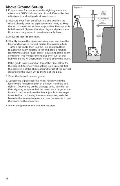
If the grade pole is used on top of the pipe, allow for<br />
the height difference when setting up (Figure K). Set<br />
the centerline of the above ground target at the correct<br />
distance to the invert OR to the top of the pipe.<br />
5. Enter the desired percent grade.<br />
6. Loosen the tripod securing knob, roughly aim the<br />
laser to the forward marker at the next manhole and<br />
tighten. Depending on the package used, use the red<br />
filter sighting scope to find the beam on a target at the<br />
forward marker and use the line adjust buttons to get<br />
to centerline, or if using the remote control, walk the<br />
beam to the forward marker and use the remote to put<br />
the beam on the centerline.<br />
7. Dial in the grade on the unit and lay pipe.<br />
Figure K<br />
ABOVE<br />
GROUND<br />
TARGET<br />
ROD READING<br />
(Backsight Elevation)<br />
HUB<br />
ELEVATION<br />
CUT TO<br />
INVERT<br />
16