NSH-566 Modularized 24 (100Base-FX) + 2G Access Switch
NSH-566 Modularized 24 (100Base-FX) + 2G Access Switch
NSH-566 Modularized 24 (100Base-FX) + 2G Access Switch

Create successful ePaper yourself
Turn your PDF publications into a flip-book with our unique Google optimized e-Paper software.
<strong>NSH</strong>-<strong>566</strong><br />
<strong>Modularized</strong><br />
<strong>24</strong> (<strong>100Base</strong>-<strong>FX</strong>) + <strong>2G</strong><br />
<strong>Access</strong> <strong>Switch</strong><br />
(Sept. 15, 2006)<br />
Management Guide
<strong>Modularized</strong> <strong>24</strong>+<strong>2G</strong> <strong>Switch</strong><br />
COPYRIGHT<br />
All rights reserved. No part of this publication may be reproduced, stored<br />
in a retrieval system, or transmitted in any form or by any means, whether<br />
electronic, mechanical, photo copying, recording or otherwise, without the<br />
prior written permission of the publisher.<br />
FCC WARNING<br />
This equipment has been tested and found to comply with the limits<br />
for a class A device, pursuant to part 15 of FCC rules. These limits<br />
are designed to provide reasonable protection against harmful<br />
interference in a commercial installation. This equipment generates, uses<br />
and can radiate radio frequency energy and, if not installed and used in<br />
accordance with the instructions, may cause harmful interference to radio<br />
communication. Operation of this equipment in a residential area is likely<br />
to cause harmful interference, in which case, the user will be required to<br />
correct the interference at the user’s own expense.<br />
CE<br />
This is a Class A product. In a domestic environment, this product<br />
may cause radio interference in which case the user may be required<br />
to take adequate measures.<br />
Take special care to read and understand all content given in the warning<br />
boxes<br />
Warning
Table of Contents<br />
1 Introduction........................................................................................1<br />
Features ...............................................................................................1<br />
Specifications......................................................................................2<br />
2 Web Management Functions..........................................................5<br />
2-1. Web Management Home Overview............................................5<br />
2-2. Denial-of-Service Protection Configuration..............................6<br />
2-3. Module Type Configuration ........................................................6<br />
2-4. Port status ....................................................................................7<br />
2-5. Port Statistics...............................................................................9<br />
2-6. Administrator ...............................................................................9<br />
2-6-1. IP Address............................................................................ 11<br />
2-6-2. Advanced ............................................................................. 11<br />
2-6-3. Console Port Information .....................................................13<br />
2-6-4. Port Controls ........................................................................13<br />
2-6-5. Abnormal Traffic Detection...................................................15<br />
2-6-6. Ethernet Loop Detection ......................................................17<br />
2-6-7. Trunking ...............................................................................17<br />
2-6-7-1. Aggregator Setting........................................................18<br />
2-6-7-2. Aggregator Information.................................................19<br />
2-6-7-3. State Activity .................................................................20<br />
2-6-8. Filter Database.....................................................................21<br />
2-6-8-1. IGMP Snooping ............................................................21<br />
2-6-8-2. Static MAC Address......................................................22<br />
2-6-8-3. MAC Filtering................................................................23<br />
2-6-9. VLAN Configuration .............................................................<strong>24</strong><br />
2-6-9-1. Port Based VLAN .........................................................26<br />
2-6-9-2. 802.1q VLAN (Tagged Based VLAN) ...........................27<br />
2-6-10. Spanning Tree....................................................................33<br />
2-6-11. Port Mirroring......................................................................37<br />
2-6-12. SNMP.................................................................................38<br />
2-6-13. Security Manager...............................................................39<br />
2-6-14. TFTP Update Firmware......................................................40<br />
2-6-15. Configuration Backup.........................................................41<br />
2-6-15-1. TFTP Backup Configuration .......................................41<br />
2-6-15-2. TFTP Restore Configuration.......................................41<br />
2-6-15-3. TFTP Import Text Configuration File...........................42<br />
2-6-15-4. TFTP Export Text Configuration File ..........................43<br />
2-6-16. Reboot................................................................................43<br />
2-6-17. Network Tree......................................................................44<br />
3 Console Xmodem - Update Firmware............................................45
<strong>Modularized</strong> <strong>24</strong>+<strong>2G</strong> <strong>Switch</strong><br />
4 Console Menu Line..........................................................................48<br />
4-1. Main Menu ..................................................................................48<br />
4-2. <strong>Switch</strong> Static Configurations....................................................49<br />
4-2-1. Port Configuration ................................................................50<br />
4-2-2. Port Abnormal Traffic Detection ...........................................51<br />
4-2-3. Ethernet Loop Detection ......................................................54<br />
4-2-4. Trunk Configurations............................................................55<br />
4-2-5. VLAN Configuration .............................................................57<br />
4-2-5-1. Create a VLAN Group ..................................................59<br />
4-2-5-2. Edit / Delete A VLAN Group .........................................61<br />
4-2-5-3. Groups Sort Mode ........................................................62<br />
4-2-6. Misc. Configuration ..............................................................64<br />
4-2-6-1. MAC Age Interval..........................................................64<br />
4-2-6-2. Broadcast Storm Filtering .............................................65<br />
4-2-6-3. Max Bridge Transmit Delay Bound...............................65<br />
4-2-6-4. Port Security .................................................................66<br />
4-2-6-5. Collisions Retry Forever ...............................................67<br />
4-2-6-6. Hash Algorithm .............................................................68<br />
4-2-6-7. Broadcast Filtering........................................................68<br />
4-2-6-8. Module Type Configuration ..........................................69<br />
4-2-7. Administration Configuration ................................................70<br />
4-2-7-1. Change Username .......................................................70<br />
4-2-7-2. Change Password ........................................................71<br />
4-2-7-3. Device Information........................................................71<br />
4-2-7-4. IP Configuration............................................................72<br />
4-2-7-5. <strong>Switch</strong> Denial-of-Service Protection.............................72<br />
4-2-7-6. Network Configuration..................................................73<br />
4-2-7-7. Add Static Network Device ...........................................73<br />
4-2-8. Port Mirroring Configuration.................................................75<br />
4-2-9. Priority Configuration ...........................................................76<br />
4-2-9-1. Port Static Priority.........................................................76<br />
4-2-9-2. 802.1p Priority Configuration........................................76<br />
4-2-10. MAC Address Configuration...............................................77<br />
4-2-10-1. Static MAC Address....................................................78<br />
4-2-10-2. Filtering MAC Address................................................80<br />
4-3. Protocol Related Configuration ...............................................83<br />
4-3-1. Spanning Tree Protocol (STP) .............................................84<br />
4-3-1-1.STP Enable ...................................................................84<br />
4-3-1-2. System Configuration ...................................................85<br />
4-3-1-3. Per Port Configurations ................................................85<br />
4-3-2. SNMP...................................................................................86<br />
4-3-2-1. System Options ............................................................87
4-3-2-2. Community Strings .......................................................87<br />
4-3-2-3. Trap Managers .............................................................88<br />
4-3-3.GVRP ....................................................................................89<br />
4-3-4. IGMP ....................................................................................89<br />
4-3-5. LACP....................................................................................90<br />
4-3-5-1. Working Port Setting.....................................................91<br />
4-3-5-2. State Activity .................................................................91<br />
4-3-5-3. LACP Status .................................................................92<br />
4-3-6. 802.1x Protocol ....................................................................93<br />
4-3-6-1. 802.1x Enable...............................................................93<br />
4-3-6-2. 802.1x System Configuration....................................94<br />
4-3-6-3. 802.1x PerPort Configuration .......................................95<br />
4-3-6-4. 802.1x Miscellaneous Configuration ............................96<br />
4-4. Status and Counters..................................................................97<br />
4-4-1. Port Status............................................................................97<br />
4-4-2. Port Counters.......................................................................98<br />
4-4-3. System Information ..............................................................99<br />
4-4-4. Network Information...........................................................100<br />
4-5. Reboot <strong>Switch</strong>..........................................................................100<br />
4-5-1. Default................................................................................101<br />
4-5-2. Restart................................................................................101<br />
4-6. TFTP Update Firmware............................................................101<br />
4-6-1. TFTP Update Firmware......................................................102<br />
4-6-2. Restore Configuration File .................................................102<br />
4-6-3. Backup Configuration File..................................................103<br />
4-6-4. TFTP Import Text Configuration File ..................................104<br />
4-6-5. TFTP Export Text Configuration File..................................105<br />
5 Menu-Driven Interface via Telnet................................................107<br />
6 Troubleshooting..................................................................................108<br />
Appendix A ..........................................................................................109<br />
Application Examples ....................................................................109<br />
Building to Building (Small Campus)........................................109<br />
Enterprise Server Aggregation.................................................109<br />
Appendix B .......................................................................................... 111<br />
802.1q Tag-VLAN Application Example ........................................ 111<br />
Network Topology .........................................................................112<br />
Appendix C ..........................................................................................119<br />
Protocol VLAN Application Example ............................................119<br />
Appendix D ..........................................................................................1<strong>24</strong><br />
System Configuration File Example .............................................1<strong>24</strong><br />
Contact Us ...........................................................................................126
<strong>Modularized</strong> <strong>24</strong>+<strong>2G</strong> <strong>Switch</strong><br />
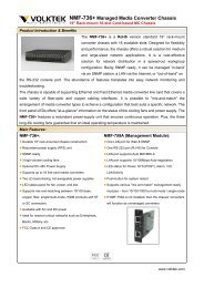
1 Introduction<br />
Emanating from our expertise in developing network communication<br />
solutions, the <strong>Modularized</strong> <strong>24</strong>+<strong>2G</strong> <strong>Access</strong> <strong>Switch</strong> incorporates<br />
leading-edge switching technology and high port density within a slim<br />
1-rack unit chassis. The <strong>Switch</strong> represents an industry first as no other<br />
switch in the market today can match the unique 3 x 8-Port modules, 2<br />
GBIC slots plus console port design. This innovation offers the ultimate in<br />
flexibility and freedom to "mix-and-match" in terms of cabling (fiber +<br />
copper) and speed (Ethernet to Gigabit).<br />
Features<br />
• Management via Console, Telnet and Web Browser User<br />
Interfaces<br />
• Management via SNMP<br />
• Console and Telnet settings using Menu-Driven Interface<br />
• 3 x 8 10/100 Ethernet plus 2 GBIC uplink ports available<br />
• Support up to 7 trunk groups<br />
• Supports 802.3x flow control for full duplex mode and<br />
collision-based backpressure for half-duplex mode<br />
• Supports Head of Line (HOL) blocking prevention<br />
• Supports broadcast storm filtering<br />
• Supports 14k MAC address entries<br />
• Supports port-based VLAN, protocol based VLAN and 802.1q<br />
tag-based VLAN<br />
• GVRP<br />
• IGMP Snooping<br />
1
<strong>Modularized</strong> <strong>24</strong>+<strong>2G</strong> <strong>Switch</strong><br />
Specifications<br />
Performance<br />
Throughput:<br />
14,880 pps for 10Mbps Ethernet<br />
148,800 pps for 100Mbps Ethernet<br />
1,488,000 pps for 1000Mbps Ethernet<br />
Max. Distance: UTP: 100 meters (Category 5e or better)<br />
Connectors and Cabling<br />
100Mbps Fiber:<br />
2,000 meters (62.5/125 micron fiber cabling)<br />
20,000 meters (9/125 micron fiber cabling)<br />
30,000 meters (9/125 micron fiber cabling)<br />
60,000 meters (9/125 micron fiber cabling)<br />
1000Mbps Fiber:<br />
220 meters (62.5/125 micron fiber cabling)<br />
10,000 meters (9/125 micron fiber cabling)<br />
Ports:<br />
3x Fast Ethernet slots (for 8-port modules);<br />
2x GBIC<br />
Module Types: 4-port 100Mbps ST, fiber<br />
4-port 100Mbps SC, fiber<br />
8-Port 100Mbps LC, fiber<br />
8-Port 100Mbps MT-RJ, fiber (Produce to order)<br />
8-Port 10/100Mbps RJ-45<br />
8-Port 100Mbps WDM fiber<br />
2-Port Gigabit (GBIC)<br />
Control:<br />
Out-of-band control: RS-232<br />
In-band control: RJ-45, Fiber<br />
2
Power Characteristics<br />
<strong>Modularized</strong> <strong>24</strong>+<strong>2G</strong> <strong>Switch</strong><br />
AC Input Voltage:<br />
Output:<br />
90 to <strong>24</strong>0V AC (auto-ranging) 50 to 60 Hz<br />
3.3V DC, 20A & 5V, 1A (71W)<br />
Environmental Characteristics<br />
Operating:<br />
Temperature: 0 o C to 45 o C (32 o F to 113 o F)<br />
Relative Humidity: 5% to 90%, non-condensing<br />
Non-Operating / Storage:<br />
Temperature: -10 o C to 70 o C (-13 o F to 158 o F)<br />
Relative Humidity: 5% to 90%, non-condensing<br />
Physical Characteristics<br />
Height:<br />
Width:<br />
Depth:<br />
Weight:<br />
Mounting:<br />
1.73" (4.4 cm)<br />
17.32" (44 cm)<br />
11.22" (28.5 cm)<br />
9.48lbs (4.3kg) fully loaded<br />
Standard 19" Rack-mount case<br />
Network Management<br />
System Configuration:<br />
Spanning Tree Algorithm:<br />
Console port, Telnet<br />
IEEE 802.1d provides redundant link<br />
support<br />
Port-based, Protocol-based or 802.1q VLAN's:<br />
Up to 256 VLANs, with GVRP for<br />
dynamic VLAN registration<br />
Link Aggregation:<br />
up to 4 ports can be combined into a fat<br />
pipe, 7 trunks<br />
3
<strong>Modularized</strong> <strong>24</strong>+<strong>2G</strong> <strong>Switch</strong><br />
LEDs:<br />
Modular Ports:<br />
10/100Mbps: Green, illuminates when data transmission rate 100Mbp<br />
LNK ACT: Green, flashing or illuminated when link pulses from a<br />
compliant device is established, and when transmitting<br />
or receiving data packets<br />
FDX: Amber, illuminated when in full duplex mode<br />
Gigabit Ports:<br />
LNK ACT:<br />
Green, flashing or illuminated when link pulses from a<br />
compliant dev ice<br />
Standards and Compliance<br />
IEEE 802.3<br />
IEEE 802.3u<br />
IEEE 802.3x<br />
IEEE 802.3z<br />
IEEE 802.1d<br />
IEEE 802.1p<br />
IEEE 802.1q<br />
RFC 1350<br />
10BASE-T specification<br />
100BASE-TX and 100BASE-<strong>FX</strong> specification<br />
Full Duplex on 10BASE-T and 100BASE-TX ports<br />
1000BASE-SX specification<br />
Spanning-Tree Protocol<br />
Priority Queues<br />
VLAN Tagging<br />
TFTP<br />
Electromagnetic Compatibility<br />
FCC Part 15 of Class A<br />
CE approved<br />
4
<strong>Modularized</strong> <strong>24</strong>+<strong>2G</strong> <strong>Switch</strong><br />
2 Web Management Functions<br />
The <strong>Switch</strong> management agent can be access via a web browser,<br />
however when setting up the IP or other “first time” settings, it is<br />
recommended that you go to section three and use console mode to<br />
secure a direct connection and to modify them.<br />
Default Address:<br />
MAC Address: (Factory set and unique for each device)<br />
IP Address: 192.168.0.254<br />
Subnet Mask: 255.255.255.0<br />
Default Gateway: 192.168.0.1<br />
User Name: admin<br />
Password: (no default password)<br />
The IP address of the <strong>Switch</strong> used for writing this manual has been<br />
set via console mode to 192.168.0.197.<br />
To access the <strong>Switch</strong>, open a web browser and key in the <strong>Switch</strong>’s IP<br />
address. Enter username and password (default is no password) and<br />
click on the button.<br />
2-1. Web Management Home Overview<br />
This is the Main Menu Home Page.<br />
5
<strong>Modularized</strong> <strong>24</strong>+<strong>2G</strong> <strong>Switch</strong><br />
Description: Display the name of device type.<br />
MAC Address: The unique hardware address assigned by<br />
manufacturer (default)<br />
Firmware Version: Display the <strong>Switch</strong>’s firmware version.<br />
2-2. Denial-of-Service Protection Configuration<br />
The <strong>Switch</strong> can be protected from denial-of-service attacks. If the user<br />
specifies all the IP addresses from which the <strong>Switch</strong> can be managed, the<br />
<strong>Switch</strong> will discard all management packets from other sources.<br />
This function can be enabled or disabled. The selected IP addresses will<br />
be granted management rights.<br />
2-3. Module Type Configuration<br />
The switch is modularized. In addition to two GBIC ports, there are three<br />
modules selectable for your needs. For the different type modules, some<br />
module/port settings maybe need to be reconfigured. You can configure<br />
the module type by this function. The system can also configure all the<br />
6
<strong>Modularized</strong> <strong>24</strong>+<strong>2G</strong> <strong>Switch</strong><br />
port settings of the module to the pre-defined values for you. If some of<br />
the detail settings of each port do not meet your needs, you can change<br />
them on a port-by-port basis from the Port Controls Page. The default<br />
module type is 8-port 10/100 Base-TX RJ-45.<br />
Available module types:<br />
1. No Module<br />
2. 8-Port 10/100 Base-TX RJ-45<br />
3. 4-Port 100 Base-<strong>FX</strong> ST/SC<br />
4. 8-Port 100 Base-<strong>FX</strong> LC<br />
5. 8-Port 100 Base-<strong>FX</strong> MT-RJ<br />
6. 8-Port 100 Base-<strong>FX</strong> BiDi<br />
Warning: The modules are not hot-swappable. You must turn<br />
off the power before you change the modules. Failure to do so may<br />
result in damage to the <strong>Switch</strong>.<br />
2-4. Port status<br />
This screen shows every port status that was set by the user – and the<br />
negotiation results.<br />
7
<strong>Modularized</strong> <strong>24</strong>+<strong>2G</strong> <strong>Switch</strong><br />
1. State: Displays port statuses disable or enable. “unlink” will be<br />
treated as “off ”.<br />
2. Link Status: Down is “No Link”, UP is “Link”.<br />
3. Auto-Negotiation: Display the auto-negotiation mode:<br />
auto/force/NWay.<br />
4. Speed status: Display 1000Mbps or 100Mbps or 10Mbps speed,<br />
port 1- <strong>24</strong> are 10/100Mbps (depending on the modular card used),<br />
port 25-26 are 1000Mbps.<br />
5. Duplex status: Display full duplex or half-duplex mode.<br />
6. Flow Control:<br />
Full: Display the flow control status is enabled or disabled in full<br />
mode.<br />
Half: Display the backpressure is enabled or disabled in half mode.<br />
7. Rate Control: Display the rate control setting.<br />
Ingr: Display the port effective ingress rate of user setting.<br />
Egr: Display the port effective egress rate of user setting.<br />
8
<strong>Modularized</strong> <strong>24</strong>+<strong>2G</strong> <strong>Switch</strong><br />
8. Priority: Display the port static priority status is High or Low or<br />
disable.<br />
9. Port Security: Display the port security is enabled or disabled.<br />
10. Config: Display the state of user setting.<br />
11. Actual: Display the negotiated result.<br />
2-5. Port Statistics<br />
Port statistics provide a summary of the current switch’s status, including<br />
on/off state, link status, good or bad packets transmitting and receiving,<br />
aborted packets, collisions and dropped packets.<br />
2-6. Administrator<br />
9
<strong>Modularized</strong> <strong>24</strong>+<strong>2G</strong> <strong>Switch</strong><br />
There are many management functions that could be accessed via the<br />
web browser. The main menu system lists all the functions. Simply click<br />
on each item to go to the appropriate page.<br />
10
2-6-1. IP Address<br />
<strong>Modularized</strong> <strong>24</strong>+<strong>2G</strong> <strong>Switch</strong><br />
The user can manually configure the IP Settings. Simply click on the IP<br />
address field and enter the address, then click the “Apply” button to<br />
change the address.<br />
Note: The user must reset/restart the <strong>Switch</strong> in order to use the new IP address<br />
setting.<br />
2-6-2. Advanced<br />
Miscellaneous Setting:<br />
MAC Address Age-out Time: Type the number of seconds that an<br />
inactive MAC address remains in the <strong>Switch</strong>'s address table. The valid<br />
range is 300~765 seconds. The default is 300 seconds.<br />
Max bridge transmit delay bound control: Limit the packets queuing<br />
time in the <strong>Switch</strong>. If enable, the packets queued exceed this time will be<br />
dropped. The valid values are 1 sec, 2 sec, 4 sec and off.<br />
Enable Low Queue Delay Bound: Limit the low priority packets queuing<br />
time in the <strong>Switch</strong>. If the low priority packets stay in the <strong>Switch</strong> exceed the<br />
Max Delay Time, it will be sent. The valid range is 1~255 ms.<br />
NOTE:<br />
Make sure that “Max bridge transit delay bound control” is enabled<br />
before activating the Delay Bound.<br />
11
<strong>Modularized</strong> <strong>24</strong>+<strong>2G</strong> <strong>Switch</strong><br />
Broadcast Storm Filter: To configure broadcast storm control, enable it<br />
and set the upper threshold for individual ports. The threshold is the<br />
percentage of the port's total bandwidth used by broadcast traffic. When<br />
broadcast traffic for a port rises above this threshold, broadcast storm<br />
control will activate. The valid threshold values are 5%, 10%, 15%, 20%,<br />
25% and OFF.<br />
Priority Queue Service settings:<br />
First Come First Service (FCFS): The sequence of packets sent<br />
depends on the order they arrive.<br />
All High before Low (AHBL): The high priority packets are sent before<br />
low priority packets.<br />
Weighted Round Robin (WRR): Select the preferred ratio of high and<br />
low priority packets sent by the <strong>Switch</strong> in its priority queue. These options<br />
represent the number of high priority packets sent before one low priority<br />
packet is sent. For example, 5 High: 2 Low, means that the <strong>Switch</strong> sends<br />
5 high priority packets before sending 2 low priority packet.<br />
QoS Policy - Priority Levels: 0~7 QoS levels can be assigned to<br />
designated high or low priority.<br />
Collisions Retry Forever: Disable – In half-duplex, if collision occurs,<br />
12
<strong>Modularized</strong> <strong>24</strong>+<strong>2G</strong> <strong>Switch</strong><br />
the <strong>Switch</strong> will retry send 48 times before dropping the frame.<br />
Enable – In half-duplex, if collision occurs, the <strong>Switch</strong> will retry to send<br />
packets indefinitely.<br />
2-6-3. Console Port Information<br />
Console is a standard UART interface to communicate with the Serial<br />
Port. The user can launch windows HyperTerminal program to link with<br />
the <strong>Switch</strong>. See section three for details<br />
Bits per seconds: 38400<br />
Data bits: 8<br />
Parity: none<br />
Stop Bits: 1<br />
Flow control: none<br />
2-6-4. Port Controls<br />
Use this page to change the status of each port.<br />
13
<strong>Modularized</strong> <strong>24</strong>+<strong>2G</strong> <strong>Switch</strong><br />
Explanation of Fields:<br />
1. State: User can disable or enable this port control.<br />
2. Auto-Negotiation: User can set auto-negotiation modes:<br />
a. Force - specify the speed/duplex on this port<br />
b. NWay Force - specify the speed/duplex on this port with<br />
auto-negotiation enabled.<br />
c. Auto – for the <strong>Switch</strong> to automatically determine the highest<br />
speed and duplex mode possible<br />
3. Speed: User can set 100Mbps or 10Mbps speed on Port1~Port<strong>24</strong><br />
(depending on module card specifications), 1000Mbps speed on<br />
port25~port26.<br />
4. Duplex: User can set full duplex or half-duplex mode for each port.<br />
5. Flows control:<br />
Full: User can set full - flow control function (pause).<br />
Half: User can set half – flow control (backpressure).<br />
6. Rate Control: port1 ~ port <strong>24</strong>, supports by-port ingress and egress<br />
rate control. For example, assume port 1 is 10Mbps, users can set its<br />
effective egress rate to 1Mbps, ingress rate is 500Kbps. The <strong>Switch</strong><br />
14
<strong>Modularized</strong> <strong>24</strong>+<strong>2G</strong> <strong>Switch</strong><br />
will perform flow control or backpressure to confine the ingress rate to<br />
meet the specified rate.<br />
Ingress: Type the port effective ingress rate. The valid range is 0 ~<br />
1000. The unit is 100Kbps<br />
0: disable rate control. (i.e. no rate limitation)<br />
1 ~ 1000: valid rate value<br />
Egress: Type the port effective egress rate. The valid range is<br />
0~1000. The unit is 100Kbps.<br />
0: disable rate control.<br />
1 ~ 1000: valid rate value.<br />
7. Priority: This static priority based on port, if you set the port to high<br />
priority, the priority of incoming packets to this port will always be<br />
high.<br />
8. Port Security: A port in security mode will be “locked” without<br />
permission of address learning. Only the incoming packets with<br />
SMAC already existing in the address table can be forwarded. User<br />
can disable the port from learning any new MAC addresses, and then<br />
use the static MAC addresses screen to define a list of MAC<br />
addresses that can use the secure port. Enter the settings, and then<br />
click “Apply” to set the <strong>Switch</strong>.<br />
2-6-5. Abnormal Traffic Detection<br />
The Abnormal Traffic Detection function allows the user to configure the<br />
bandwidth threshold up to which the specified ports can receive<br />
broadcast packets. If the incoming broadcast packets exceed this limit,<br />
the <strong>Switch</strong> can disable that port for a specified time or permanently<br />
(‘forever’).<br />
15
<strong>Modularized</strong> <strong>24</strong>+<strong>2G</strong> <strong>Switch</strong><br />
Attribute<br />
Meaning<br />
Abnormal Traffic Detection Enable “Enable” or “Disable” this function<br />
Abnormal Packet Limit The bandwidth threshold for<br />
incoming broadcast packets<br />
Abnormal Protection Interval Enable: Disable the port forever if<br />
Forever<br />
the incoming broadcast packets<br />
exceed the bandwidth threshold<br />
continuously in the specified<br />
monitor time interval.<br />
Disable: Disable the port only for a<br />
specified time interval if the<br />
incoming broadcast packets<br />
exceed the bandwidth threshold<br />
continuously in the specified<br />
monitor time interval<br />
Abnormal Protection Interval The time period that the port will<br />
be disabled if the incoming<br />
broadcast packets exceed the<br />
bandwidth limit<br />
Abnormal Protection Monitor<br />
Times<br />
Port / Protection<br />
The period over which a port must<br />
experience an overflow of<br />
broadcast packets before being<br />
disabled<br />
Enable or Disable the Abnormal<br />
Traffic Detection function per port<br />
16
2-6-6. Ethernet Loop Detection<br />
<strong>Modularized</strong> <strong>24</strong>+<strong>2G</strong> <strong>Switch</strong><br />
The Ethernet Loop Detection function provides a means to detect the loop<br />
condition on the sub-network connected to the port. If such a condition is<br />
detected, the port will be disabled by the <strong>Switch</strong>.<br />
Users can enable or disable the function for the whole <strong>Switch</strong> or per port.<br />
If the port is disabled because the loop condition has been detected, the<br />
port needs to be enabled again manually.<br />
2-6-7. Trunking<br />
The Link Aggregation Control Protocol (LACP) provides a standardized<br />
means for exchanging information between Partner Systems on a link to<br />
allow their Link Aggregation Control instances to reach agreement on the<br />
identity of the Link Aggregation Group to which the link belongs. Move the<br />
link to that Aggregation Group and enable its transmission and reception<br />
functions in an orderly manner.<br />
Link Aggregation lets you group up to four ports into a single dedicated<br />
connection. If more than four ports attached to the same <strong>Switch</strong> have<br />
LACP enabled, the additional ports will be placed in standby mode, and<br />
will only be enabled if one of the active links fails. All ports on both ends of<br />
an LACP trunk must be configured for full duplex, either by forced mode<br />
or auto-negotiation. This feature can expand bandwidth to a device on the<br />
network. LACP operation requires full duplex mode, for more detailed<br />
17
<strong>Modularized</strong> <strong>24</strong>+<strong>2G</strong> <strong>Switch</strong><br />
information, please refer to IEEE 802.3ad.<br />
2-6-7-1. Aggregator Setting<br />
1. System Priority: LACP system priority is used to determine link<br />
aggregation group (LAG) membership, and to identify this device to<br />
other switches during LAG negotiations. (Range: 0-65535)<br />
a. Ports must be configured with the same system priority to join the<br />
same LAG.<br />
b. System priority is combined with the switch’s MAC address to<br />
form the LAG identifier. This identifier is used to indicate a specific<br />
LAG during LACP negotiations with other systems.<br />
c. Given a pair of <strong>Switch</strong>es trunked together, the switch with the<br />
lowest system priority value has the highest priority and will behave<br />
as the active LACP.<br />
2. Group ID: There are seven trunk groups to provide configures.<br />
Choose the "group id" and click "Get".<br />
3. LACP: If enable, the group is LACP static trunking group. If disabled,<br />
the group is local static trunking group. All ports support LACP<br />
dynamic trunking groups. If connecting to a device that also supports<br />
LACP, the LACP dynamic trunking group will be created<br />
automatically.<br />
4. Work ports: Work ports are typically a subset of the total ports<br />
18
<strong>Modularized</strong> <strong>24</strong>+<strong>2G</strong> <strong>Switch</strong><br />
selected for trunking. They are the primary working ports during<br />
normal operation. The switch allows for a maximum of four ports<br />
which can be aggregated at the same time. If LACP static trunking<br />
group is active, the surplus ports function as standby and are able to<br />
aggregate if any work ports fail. If local static trunking group is active,<br />
the number of work ports must be the same as the group member<br />
ports.<br />
To form a trunking group, simply select the ports to join the trunking group<br />
from the available ports list on the right pane. Click
<strong>Modularized</strong> <strong>24</strong>+<strong>2G</strong> <strong>Switch</strong><br />
2-6-7-3. State Activity<br />
Active (select): The port automatically sends LACP packets.<br />
Passive (no select): The port does not automatically send LACP packets,<br />
and respond only if it receives LACP packets from another networking<br />
device.<br />
A link having either two active LACP ports or one active port can perform<br />
dynamic LACP trunking. A link has two passive LACP ports will not<br />
perform dynamic LACP trunking because both ports are waiting for LACP<br />
packet from another networking device.<br />
If the switch is set to be an active LACP’s actor, and ports are selected for<br />
trunking (from the Port Trunking > Aggregator Settings, shown in the<br />
previous section) then all ports selected to participate in trunking that<br />
port’s LACP State will be automatically set to Active in the screen below.<br />
The LACP State Activity may be inactivated by un-checking the status<br />
box next to the port.<br />
20
<strong>Modularized</strong> <strong>24</strong>+<strong>2G</strong> <strong>Switch</strong><br />
2-6-8. Filter Database<br />
2-6-8-1. IGMP Snooping<br />
21
<strong>Modularized</strong> <strong>24</strong>+<strong>2G</strong> <strong>Switch</strong><br />
The <strong>Switch</strong> supports IP multicast, you can enable IGMP on the Filtering<br />
and Forwarding > IGMP Snooping page (shown above). You can view<br />
different multicast group, VID and member ports here. IP multicast<br />
addresses range from 2<strong>24</strong>.0.0.0 to 239.255.255.255.<br />
The Internet Group Management Protocol (IGMP) is an internal protocol<br />
of the Internet Protocol (IP) suite. IP manages multicast traffic by using<br />
switches, routers, and hosts that support IGMP. Enabling IGMP allows<br />
the ports to detect IGMP queries and report packets and manage IP<br />
multicast traffic through the <strong>Switch</strong>. IGMP have three fundamental types<br />
of messages. See table below:<br />
Query<br />
Report<br />
Leave Group<br />
Message Description<br />
A message sent from the querier (IGMP router or switch) asking for a<br />
response from each host belonging to the multicast group.<br />
A message sent by a host to the querier to indicate that the host wants<br />
to be or is a member of a given group indicated in the report message.<br />
A message sent by a host to the querier to indicate that the host has<br />
quit being a member of a specific multicast group.<br />
2-6-8-2. Static MAC Address<br />
When you add a static MAC address, it is stored in the <strong>Switch</strong>'s address<br />
table regardless of whether the device is physically connected to the<br />
<strong>Switch</strong>. This saves the <strong>Switch</strong> from having to re-learn a device's MAC<br />
address when the device is disconnected or powered-off, and is then<br />
active in the network again.<br />
22
<strong>Modularized</strong> <strong>24</strong>+<strong>2G</strong> <strong>Switch</strong><br />
Adding a new static MAC address<br />
1. From the main menu, click Administrator Filter Database Static MAC<br />
Address.<br />
2. In the MAC address box, enter the MAC address to and from which<br />
the port should permanently forward traffic, regardless of the device’s<br />
network activity.<br />
3. In the Port Number box, enter a port number.<br />
4. If tag-based (IEEE 802.1q) VLANs are set up on the <strong>Switch</strong>, static<br />
addresses are associated with individual VLANs. Type the VID<br />
(tag-based VLANs) associated with the MAC address.<br />
5. Click on the “Add” button.<br />
2-6-8-3. MAC Filtering<br />
MAC address filtering allows the <strong>Switch</strong> to drop unwanted traffic. Traffic is<br />
filtered based on the destination addresses.<br />
Filtering a MAC address<br />
1. In the MAC Address box, enter the MAC addresses that are to be<br />
filtered.<br />
2. If tag-based (802.1q) VLAN are set up on the <strong>Switch</strong>, in the VLAN ID<br />
box type the VID associated with the MAC address.<br />
3. Click the on “Add” button.<br />
4. Choose the MAC address that you want to delete and then click on<br />
the “Delete” button.<br />
23
<strong>Modularized</strong> <strong>24</strong>+<strong>2G</strong> <strong>Switch</strong><br />
2-6-9. VLAN Configuration<br />
A Virtual LAN (VLAN) is a logical network grouping that limits the<br />
broadcast domain. It allows you to isolate network traffic so only members<br />
of the VLAN receive traffic from the same VLAN members. Basically,<br />
creating a VLAN in a switch is logically equivalent of reconnecting a group<br />
of network devices to another Layer 2 switch. However, all the network<br />
devices are still plug into the same switch physically. The <strong>Switch</strong> supports<br />
port-based, 802.1q (tagged-based) and protocol-based VLAN in web<br />
management page. In the default configuration, VLAN support is disabled.<br />
There are a few configuration examples in Appendix B for your reference.<br />
Support Port-based VLAN<br />
Packets can go among only members of the same VLAN group. Note all<br />
unselected ports are treated as belonging to another single VLAN. If the<br />
port-based VLAN is enabled, the VLAN-tagging is ignored.<br />
GROUP 1<br />
SALES<br />
GROUP 2<br />
R&D<br />
<strong>24</strong>
<strong>Modularized</strong> <strong>24</strong>+<strong>2G</strong> <strong>Switch</strong><br />
Support Tag-based VLAN (IEEE 802.1q VLAN)<br />
Tagged-based VLAN is an IEEE 802.1q specification standard. Therefore,<br />
it is possible to create a VLAN across devices from different switch<br />
vendors. IEEE 802.1q VLAN uses a technique to insert a “tag” into the<br />
Ethernet frames. Tags contain a VLAN Identifier (VID) that represents the<br />
VLAN numerically.<br />
Support Protocol-based VLAN<br />
In order for an end station to send packets to different VLANs, it has to<br />
either:<br />
a. Be capable of tagging packets it sends with VLAN tags, OR<br />
b. Be attached to a VLAN-aware bridge that is capable of<br />
classifying and tagging the packet with different VLAN ID based<br />
on not only default PVID but also other information about the<br />
packet, including its protocol (such as Novell IPX and<br />
AppleTalk’s EtherTalk)<br />
The feature can be applied for accommodating devices that you want to<br />
participate in the VLAN, but don’t support tagging. Therefore, the system<br />
can add VLAN tags to untagged frames which are based on PVID or on<br />
different protocols. (Please see next section for PVID introduction and<br />
configuration)<br />
The <strong>Switch</strong> will support protocol-based VLAN classification by means of<br />
both built-in knowledge of layer 2 packet formats used by selected<br />
popular protocols, such as Novell IPX and AppleTalk’s EtherTalk, and<br />
some degree of programmable protocol matching capability. A port can<br />
join more than one different protocol VLANs, but a port can’t apply a<br />
same protocol twice for the VLAN configuration purpose. Otherwise you<br />
will see the error message: “Save fail for ethertype conflict” when trying to<br />
configure VLANs.<br />
25<br />
VID=3<br />
R&D
<strong>Modularized</strong> <strong>24</strong>+<strong>2G</strong> <strong>Switch</strong><br />
VID=2<br />
SALES<br />
2-6-9-1. Port Based VLAN<br />
Create a new port-based VLAN<br />
1. Click Add to create a new VLAN group.<br />
2. Enter the VLAN name, group ID and select the members for the new<br />
VLAN.<br />
3. Click Apply.<br />
4. If there are many groups that over the limit of one page, you can click<br />
the “NextPage” to view other VLAN groups.<br />
26
Adding Ports and Trunks to the VLAN<br />
<strong>Modularized</strong> <strong>24</strong>+<strong>2G</strong> <strong>Switch</strong><br />
For Port Based VLANs, all available ports (or trunks) which may<br />
participate in a VLAN can be selected for participation in the Port Based<br />
VLAN Configuration screen shown above. If trunk groups exist, they are<br />
displayed as: TRK1, TRK2, etc. and displayed along with the <strong>Switch</strong>es<br />
ports in the left hand side panel. You can combine trunk groups and<br />
ports together to form a VLAN simply by selecting the available ports<br />
trunks from the left panel, and pressing the Add>> button. Remove ports<br />
or trunks by selecting and pressing
<strong>Modularized</strong> <strong>24</strong>+<strong>2G</strong> <strong>Switch</strong><br />
How 802.1q VLAN works<br />
According to the VID information in the tag, the switch forward and filter<br />
the frames among ports. These ports with same VID can communicate<br />
with each other. IEEE 802.1q VLAN functions contains the following<br />
three tasks, Ingress Process, Forwarding Process and Egress Process.<br />
1. Ingress Process:<br />
Each port is capable of passing tagged or untagged frames. Ingress<br />
Process identifies if the incoming frames contain tag, and classifies the<br />
incoming frames belonging to a VLAN. Each port has its own Ingress rule.<br />
If Ingress rule accept tagged frames only, the switch port will drop all<br />
incoming non-tagged frames.<br />
a. When a tagged frame is received on a port, it carries a tag header<br />
that has a explicit VID. Ingress Process directly passes the<br />
tagged frame to Forwarding Process.<br />
b. An untagged frame doesn't carry any VID to which it belongs.<br />
When a untagged frame is received, Ingress Process insert a tag<br />
contained the PVID into the untagged frame. Each physical port<br />
has a default VID called PVID (Port VID). PVID is assigned to<br />
untagged frames or priority tagged frames (frames with null (0)<br />
VID) received on this port.<br />
28
<strong>Modularized</strong> <strong>24</strong>+<strong>2G</strong> <strong>Switch</strong><br />
After Ingress Process, all frames have 4-bytes tag and VID information,<br />
and then go to Forwarding Process.<br />
2. Forwarding Process:<br />
The Forwarding Process decides to forward the received frames<br />
according to the Filtering Database. If you want to allow the tagged<br />
frames can be forwarded to certain port, this port must be the egress port<br />
of this VID. The egress port is an outgoing port for the specified VLAN,<br />
that is, frames with specified VID tag can go through this port. The<br />
Filtering Database stores and organizes VLAN registration information<br />
useful for switching frames to and from switch ports in the DVLAN table.<br />
The DVLAN table is automatically learned via GVRP protocol, and can't<br />
be created and upgraded by the<br />
administrator.<br />
3. Egress Process:<br />
The Egress Process decides if the outgoing frames but be sent tagged or<br />
untagged. Egress Process refers to the egress tag control information in<br />
Filtering Database. If the value is tagged, the outgoing frame on the<br />
egress port is tagged. If the value is untagged, the tag will be removed<br />
before frame leaves the egress port.<br />
How to create tag-based VLANS and enable/disable GVRP protocol<br />
Open the VLAN Configuration Screen and select 802.1q from the “VLAN<br />
Operation Mode”. There are 256 VLAN groups available in the <strong>Switch</strong>.<br />
Enable 802.1q VLAN, all ports on the <strong>Switch</strong> belong to a default VLAN. Its<br />
VID is 1. The default VLAN cannot be deleted.<br />
29
<strong>Modularized</strong> <strong>24</strong>+<strong>2G</strong> <strong>Switch</strong><br />
GVRP (GARP [Generic Attribute Registration Protocol] VLAN<br />
Registration Protocol)<br />
GVRP allows automatic VLAN configuration between the <strong>Switch</strong> and<br />
nodes. If the <strong>Switch</strong> is connected to a device with GVRP enabled, you<br />
can send a GVRP request using the VID of a VLAN defined on the <strong>Switch</strong>.<br />
The <strong>Switch</strong> will automatically add that device to the existing VLAN.<br />
Create a VLAN and add tagged member ports to it.<br />
30
<strong>Modularized</strong> <strong>24</strong>+<strong>2G</strong> <strong>Switch</strong><br />
The above screen is the Main Tag-based VLAN (802.1q) page<br />
1. From the main menu, click Administrator VLAN configuration,<br />
click Add then you will see the page as above.<br />
2. Type a name for the new VLAN.<br />
3. Type a VID number (between 2-4094). The default is 1 (In total,<br />
there are 255 VLANs that can be configured).<br />
4. Choose the protocol type. If you are not applying protocol VLAN,<br />
you must set the value to “NONE”. You can’t set a port to join<br />
more than one VLANs/VIDs with a same protocol.<br />
5. From the Available ports box, select ports to add to the <strong>Switch</strong><br />
and click “Add >>”. If the trunk groups exist, you can see<br />
displayed as: TRK1, TRK2, …, …, and you can configure it to be<br />
a member of the VLAN or not.<br />
6. Click “Next.” Then you can view the page as follows.<br />
7. After adding ports to the VLAN, you use the above page to set<br />
the outgoing frames as VLAN-tagged frames or not. The default<br />
is ‘Untag’. Using the dropdown box, select ‘Tag’ or ‘Untag’ and<br />
click “Apply.”<br />
Note: Unless you are sure the network has no tag-unaware devices, you<br />
should leave the default setting of the outgoing frames to “Untag”.<br />
Tag:<br />
Untag:<br />
Outgoing frames with VLAN-tagging.<br />
Outgoing frames without VLAN-tagging.<br />
31
<strong>Modularized</strong> <strong>24</strong>+<strong>2G</strong> <strong>Switch</strong><br />
Configure port VID settings<br />
From the main tag-based (IEEE 802.1q) VLAN page, click Port VID<br />
Settings. Configure port VID settings<br />
From the Main Tag-based VLAN page, click<br />
[Port VID] (shown on the insert to the right) to<br />
enter the Port VID Settings menu.<br />
Port VID (PVID)<br />
Set the port VLAN ID that will be assigned to untagged traffic on a given<br />
port. This feature is useful for accommodating devices that you want to<br />
participate in the VLAN but that don’t support tagging. Each port allows<br />
user to set one PVID, the range is 1~4095, default PVID is 1.<br />
Ports may share a same PVID, but all the PVIDs of the ports on the<br />
switch must belong to the same 256 number group segment. (For<br />
example: 1~255, 256~511,…3840~4095). This is in order to allow for<br />
faster Ingress processing of frames. The PVID will be used for VLAN ID<br />
tagging to untagged frames.<br />
Note also that the PVID must be the same as the member VLAN group<br />
IDs that the port belongs to, else the untagged traffic will be dropped.<br />
This is because the port can’t transmit a frame with a VLAN Group ID it<br />
32
33<br />
<strong>Modularized</strong> <strong>24</strong>+<strong>2G</strong> <strong>Switch</strong><br />
doesn’t belong to. If a port also joins a protocol VLAN, the <strong>Switch</strong> will<br />
apply the protocol VLAN ID to untagged frames first. If the frame doesn’t<br />
meet one of the protocols the port has defined, then the PVID will be<br />
applied for this frame.<br />
Ingress Filtering<br />
Ingress filtering lets frames belonging to a specific VLAN to be forwarded.<br />
The <strong>Switch</strong> has two ingress filtering rules as follows:<br />
Rule 1: Forward only packets with VID matching this port's configured<br />
VID. The default is “Enable”. By default, only the packets with<br />
VID matching this port’s configured VID can pass the port.<br />
Rule 2: Drop Untagged Packet. The default is “Disable”. By default,<br />
untagged packets can pass the port.<br />
2-6-10. Spanning Tree<br />
The Spanning Tree Protocol (STP) is a standardized method (IEEE<br />
802.1d) for avoiding loops in switched networks. When STP is enabled, it<br />
ensures that only one path at a time is active between any two nodes in<br />
the network. You can enable Spanning Tree Protocol by checking the<br />
“STP State” check box from the Spanning Tree Configuration > System<br />
Configuration menu (shown below). We recommend that you enable STP<br />
on all switches to ensure that only a single active path in the network<br />
exists.<br />
STA uses a distributed algorithm to select a bridging device<br />
(STA-compliant switch, bridge or router) that serves as the root of the<br />
spanning tree network. It selects a root port on each bridging device<br />
(except for the root device) which incurs the lowest path cost when<br />
forwarding a packet from that device to the root device. Then it selects a<br />
designated bridging device from each LAN which incurs the lowest path<br />
cost when forwarding a packet from that LAN to the root device. All ports<br />
connected to designate bridging devices are assigned as designated<br />
ports. After determining the lowest cost spanning tree, it enables all root<br />
ports and designated ports, and disables all other ports. Network packets<br />
are therefore only forwarded between root ports and designated ports,<br />
eliminating any possible network loops.<br />
Once a stable network topology has been established, all bridges listen<br />
for Hello BPDUs (Bridge Protocol Data Units) transmitted from the Root<br />
Bridge. If a bridge does not get a Hello BPDU after a predefined interval
<strong>Modularized</strong> <strong>24</strong>+<strong>2G</strong> <strong>Switch</strong><br />
(Maximum Age), the bridge assumes that the link to the Root Bridge is<br />
down. This bridge will then initiate negotiations with other bridges to<br />
reconfigure the network to reestablish a valid network topology.<br />
The following figure gives an illustration of how the Spanning Tree<br />
Algorithm assigns bridging device ports.<br />
1. From the Spanning Tree Configuration Menu (shown below), you can<br />
create a new value for the STP parameter, and then click the “Apply”<br />
button to set it. You can view spanning tree information the Root<br />
Bridge device from the same screen.<br />
34
<strong>Modularized</strong> <strong>24</strong>+<strong>2G</strong> <strong>Switch</strong><br />
You can view spanning tree status about the <strong>Switch</strong> from the following<br />
screen.<br />
Parameter<br />
Priority<br />
Max Age<br />
Hello Time<br />
Description<br />
You can change priority value, A value used to<br />
identify the root bridge. The bridge with the lowest<br />
value has the highest priority and is selected as<br />
the root. Enter a value from 1 to 65535.<br />
You can change Max. Age value, the number of<br />
seconds a bridge waits without receiving Spanning<br />
Tree Protocol configuration messages before<br />
attempting a reconfiguration. Enter a time in<br />
seconds from 6 to 40.<br />
You can change the Hello time value, the number<br />
of seconds between the transmissions of<br />
Spanning Tree Protocol configuration messages.<br />
Enter a time in seconds from 1 to 10.<br />
35
<strong>Modularized</strong> <strong>24</strong>+<strong>2G</strong> <strong>Switch</strong><br />
Forward Delay time You can change forward delay time, The number<br />
of seconds a port waits before changing from its<br />
Spanning Tree Protocol learning and listening<br />
states to the forwarding status. Enter a time in<br />
seconds from 4 to 30.<br />
2. From the Spanning Tree Configuration Menu, click PerPort<br />
Configuration to configure STP parameters on each port, click on<br />
the “Apply” button to set it.<br />
Parameter<br />
Port Priority<br />
Path Cost<br />
Description<br />
You can make the port more or less likely in becoming<br />
the root port. The range is between 0-255. Its default<br />
setting is 128. The lowest number has the highest<br />
priority.<br />
Specifies the path cost of the port. The <strong>Switch</strong> uses this<br />
to determine which port are the forwarding ports. The<br />
lowest numbers assigned are the forwarding ports. The<br />
range is between 1 and 65535 and the default value<br />
base on IEEE802.1d are:<br />
10Mb/s = 50-600 100Mb/s = 10-60 1000Mb/s = 3-10<br />
36
2-6-11. Port Mirroring<br />
<strong>Modularized</strong> <strong>24</strong>+<strong>2G</strong> <strong>Switch</strong><br />
Port Mirroring is a method to monitor traffic in switched networks. Traffic<br />
through ports can be monitored by one specific port. That is, traffic going<br />
in or out monitored ports will be duplicated to a mirror port.<br />
Roving Analysis State: Roving analysis is the mirroring of Fast Ethernet<br />
port traffic to another port of the same media type within a system that<br />
has an RMON probe or analyzer attached. This port allows external<br />
RMON probes (network analyzers) to monitor traffic on any switched<br />
segment.<br />
You can monitor a designated roving analysis port to: Analyze traffic loads<br />
on each segment so that you can continually optimize your network loads<br />
by moving network segments, or troubleshoot switched network problems<br />
(for example, to find out why a particular segment has so much traffic)<br />
37
<strong>Modularized</strong> <strong>24</strong>+<strong>2G</strong> <strong>Switch</strong><br />
Analysis Port: You can have as many as 16 network analyzers<br />
connected to a system. For more accurate analysis, attach the analyzer<br />
to a dedicated port instead of through a repeater. When the analyzer port<br />
is set, it cannot receive or transmit any other data. Instead, it receives<br />
only the data from the ports to be monitored.<br />
Monitor Port: The ports you want to monitor. All monitor port traffic will be<br />
copied to mirror port. You can select max 25 monitor ports in the <strong>Switch</strong>.<br />
User can choose which port that they want to monitor in only one mirror<br />
mode. For each port 1-<strong>24</strong> you wish to monitor, click the check box next<br />
to the port. When finished, click “Apply.”<br />
2-6-12. SNMP<br />
Any network management platform running the Simple Network<br />
Management Protocol (SNMP) can manage the <strong>Switch</strong> provided the<br />
Management Information Base (MIB) is installed correctly on the<br />
management station. The SNMP is a protocol that governs the transfer of<br />
information between management station and agent.<br />
1. System Options: Use this page to define management stations as trap<br />
managers and to enter SNMP community strings. User can also define<br />
a name, location, and contact person for the switch. Fill in the system<br />
options data, and then click Apply to update the changes on this page.<br />
Name: Enter a name to be used for the <strong>Switch</strong>.<br />
Location: Enter the location of the <strong>Switch</strong>.<br />
Contact: Enter the name of a person or organization.<br />
2. Community strings: serve as passwords and can be entered as one<br />
of the following:<br />
RO: Read only. Enables requests accompanied by this string to display<br />
38
MIB-object information.<br />
<strong>Modularized</strong> <strong>24</strong>+<strong>2G</strong> <strong>Switch</strong><br />
RW: Read write. Enables requests accompanied by this string to<br />
display MIB-object information and to set MIB objects.<br />
3. Trap Manager: The trap manager is a management station that<br />
receives traps, the system alerts generated by the <strong>Switch</strong>. If no trap<br />
manager is defined, no traps are issued. Create a trap manager by<br />
entering the IP address of the station and a community string the press<br />
“
<strong>Modularized</strong> <strong>24</strong>+<strong>2G</strong> <strong>Switch</strong><br />
2-6-14. TFTP Update Firmware<br />
The following menu options provide some system control functions to<br />
allow a user to update firmware and remote boot switch system:<br />
1. Install and run TFTP program (for example Turbo98) to the computer<br />
which is connected to the switch.<br />
2. Copy updated firmware image bin into TFTP servers (Turbo98)<br />
directory.<br />
3. Identify the IP address of the PC running the TFTP.<br />
4. From the Main Menu, select System Restart, then Firmware Mgmt<br />
(shown in screen below). Then select TFTP Update Firmware.<br />
5. Enter the computers IP address into the “TFPT Server IP Address”<br />
Field<br />
6. Type in the Firmware File Name.<br />
7. Press Apply.<br />
8. System will respond with “Image download completed. Would you like<br />
to update firmware” (Screen shown below)<br />
9. To update new bin image file, press .<br />
10. After update is complete, press to restart the switch.<br />
40
<strong>Modularized</strong> <strong>24</strong>+<strong>2G</strong> <strong>Switch</strong><br />
2-6-15. Configuration Backup<br />
2-6-15-1. TFTP Backup Configuration<br />
You can back up the switch system configuration in a data file, and place<br />
it on onto the TFTP server. The system configuration is saved in a binary<br />
*.dat file (example shown below is data.dat). To save the configuration file,<br />
use the page shown below to set TFTP server IP address. You can save<br />
current EEPROM value from here, then go to the TFTP restore<br />
configuration page to restore the EEPROM value.<br />
Note: the address and file name in the above screen shot are examples<br />
2-6-15-2. TFTP Restore Configuration<br />
Use this page to set TFTP server address. You can restore EEPROM<br />
value from here, but you must put back image in TFTP server, <strong>Switch</strong> will<br />
download back flash image.<br />
41
<strong>Modularized</strong> <strong>24</strong>+<strong>2G</strong> <strong>Switch</strong><br />
2-6-15-3. TFTP Import Text Configuration File<br />
In the previous section, TFTP Restore Configuration and TFTP Backup<br />
Configuration, you learned how to restore and backup configuration<br />
images saved from the EEPROM and to a TFTP server. But the data in<br />
that configuration file was in binary format, as such cannot be read<br />
directly. However, there is a method to restore and read the configuration<br />
file in plain text format.<br />
In sections 4-6-4 and 4-6 5 below, we describe the step by step procedure<br />
to both save and restore a flat text configuration file. But first, let’s<br />
mention a few important points before we begin the procedure.<br />
Saving and Importing text configuration files is similar to saving EEPROM<br />
images, you will also need to first set a TFTP server address and backup<br />
file name as shown in the example screens above. And like before, you<br />
will also need to place the configuration file in the TFTP server. The<br />
<strong>Switch</strong> will then be able to download the configuration data into the<br />
EEPROM as an executing batch command. You can easily duplicate<br />
switch configurations from switch to switch by simply downloading the<br />
same configuration data for each switch you like. If there are any changes<br />
you wish to make for any particular switch, you could modify the<br />
downloaded configuration file by any popularly used text editor, and then<br />
restore it to the switch.<br />
Note: It is strongly suggested that you use a flat text editor such as Notepad for<br />
editing the configuration file. Reason being, that some word processors<br />
tend to add unnecessary control or format codes to the text file, possibly<br />
corrupting the integrity of the file causing a file import failure.<br />
For every file import/export event, a status report is automatically created.<br />
The report is located in the file named ‘Report.txt’ located in your TFTP<br />
42
<strong>Modularized</strong> <strong>24</strong>+<strong>2G</strong> <strong>Switch</strong><br />
server. Should there be any errors during the configuration file import,<br />
you will see details in the Report.txt file. The information in the report will<br />
give you some clues about the process and if any errors occurred.<br />
An example of a typical configuration file, and the information it contains,<br />
is showed in Appendix D at the end of this section.<br />
Note: the address and file name on above screen shot are examples<br />
2-6-15-4. TFTP Export Text Configuration File<br />
Use this page to set TFTP server IP address. You can save current<br />
EEPROM values here, and then go to the TFTP Import Text Configuration<br />
File page to restore the EEPROM value. In the following example, the<br />
backup text file is config.txt. It is in plain text format and can be edited by<br />
any text editor.<br />
Note: the address and file name on above screen shot are examples<br />
2-6-16. Reboot<br />
Reboot the <strong>Switch</strong> with a software reset.<br />
43
<strong>Modularized</strong> <strong>24</strong>+<strong>2G</strong> <strong>Switch</strong><br />
2-6-17. Network Tree<br />
The “web cluster” feature will search switch nodes connected to the local<br />
network, and allows users to add/delete any network node(s) to/from the<br />
network tree. So that users not only have a network view, but also access<br />
or control switches or nodes from the local switch’s web interface. See<br />
the following diagram.<br />
44
<strong>Modularized</strong> <strong>24</strong>+<strong>2G</strong> <strong>Switch</strong><br />
3 Console Xmodem - Update Firmware<br />
The <strong>Switch</strong> provides a 1K Xmodem to update firmware via console. The<br />
application only works in 38400bps mode. There are two cases whereby<br />
the 1K Xmodem is used:<br />
Case A. User enters "1K Xmodem receiver mode" through pressing any<br />
key within 3 seconds after system is powered on.<br />
Case B. The system automatically enters "1K Xmodem receiver mode"<br />
if it detects the firmware checksum fail while booting.<br />
1. Start Xmodem receiver mode. Follow the screen cues by clicking any<br />
key.<br />
45
<strong>Modularized</strong> <strong>24</strong>+<strong>2G</strong> <strong>Switch</strong><br />
By clicking on the connected button, you will see “CCCC…”displayed on<br />
console. Select Transfer -> Send File.<br />
3. Select 1K Xmodem in the “protocol” item, and specify the path where<br />
the image file is to be sent. Then click on the “send” button.<br />
46
4. Start download image file.<br />
<strong>Modularized</strong> <strong>24</strong>+<strong>2G</strong> <strong>Switch</strong><br />
5. Finish downloading the image - the <strong>Switch</strong> system will update<br />
firmware automatic. Update firmware ok - the <strong>Switch</strong> will reboot.<br />
47
<strong>Modularized</strong> <strong>24</strong>+<strong>2G</strong> <strong>Switch</strong><br />
4 Console Menu Line<br />
Being SNMP manageable, The <strong>Switch</strong> features a serial interface to<br />
manage and to monitor the system. Attach a VT100 compatible terminal<br />
or a PC running a terminal emulation program (i.e. HyperTerminal) to the<br />
serial port on the switch’s front panel. A user can follow the Console<br />
menu to manage and control the <strong>Switch</strong>.<br />
You can type user name and password to login. The default user name is<br />
“admin”, with no default password.<br />
4-1. Main Menu<br />
There are six items on the Main Menu page. They are as follows:<br />
48
<strong>Modularized</strong> <strong>24</strong>+<strong>2G</strong> <strong>Switch</strong><br />
<strong>Switch</strong> Static Configuration:<br />
Protocol Related Configuration:<br />
function.<br />
Status and Counters:<br />
<strong>Switch</strong>.<br />
Reboot <strong>Switch</strong>:<br />
TFTP Update Firmware:<br />
Logout:<br />
Configure the <strong>Switch</strong>.<br />
Configure the protocol<br />
Show the status of the<br />
Restart the system or reset <strong>Switch</strong><br />
to default configuration.<br />
Use tftp to download image.<br />
Exit the menu line program.<br />
<br />
The control key provided in all menus as follow:<br />
Tab:<br />
Backspace:<br />
Enter:<br />
Space:<br />
Move the cursor to next item.<br />
Move the cursor to previous item.<br />
Select item.<br />
Toggle selectable items<br />
4-2. <strong>Switch</strong> Static Configurations<br />
49
<strong>Modularized</strong> <strong>24</strong>+<strong>2G</strong> <strong>Switch</strong><br />
From the <strong>Switch</strong> Configuration page, users can alter Port, Trunk, VLAN,<br />
Administrative, Port Mirroring, Priority, MAC address and Miscellaneous<br />
configurations. The following sections in this manual go over each<br />
configuration in detail.<br />
The following action menu line is provided within the configuration pages.<br />
:<br />
Exit the current page and return to previous menu.<br />
: Configure items. When finished with setting<br />
configurations, press Ctrl+A to go back action menu<br />
line.<br />
:<br />
Save all configured values.<br />
:<br />
Return to previous page.<br />
:<br />
Go to next page.<br />
4-2-1. Port Configuration<br />
This screen allows the configuration of each port. Press key to<br />
change the status of each item.<br />
50
<strong>Modularized</strong> <strong>24</strong>+<strong>2G</strong> <strong>Switch</strong><br />
InRate (100Kbps/unit): Here the user can set input rate control. Each<br />
unit is 100K. The valid range is 0~1000.<br />
0: disable rate control.<br />
1~1000: valid rate value.<br />
OutRate (100Kbps/unit): User can set output rate control. Each unit is<br />
100K. The valid range is 0~1000.<br />
0: disable rate control.<br />
1~1000: valid rate value.<br />
Enabled: User can disable or enable each port. “Yes” means that the port<br />
is enabled. “No” means the port is disabled.<br />
Auto: User can set the auto-negotiation mode.<br />
a. Force - specify the speed/duplex on this port<br />
b. NWay Force - specify the speed/duplex on this port with<br />
auto-negotiation enabled.<br />
c. Auto – for the <strong>Switch</strong> to automatically determine the highest<br />
speed and duplex mode possible<br />
Spd/Dpx: User can set 100Mbps or 10Mbps speed on port 1~port <strong>24</strong><br />
(depending on the performance of the uplink module card), 1000Mbps on<br />
port25~port26, and set full duplex or half-duplex modes.<br />
Flow Control:<br />
Full: User can enable or disable full flow control function (pause)<br />
Half: User can enable or disable half flow control function (backpressure).<br />
NOTE:<br />
1. Selecting will only save the new configuration on the current page.<br />
2. If any static trunk groups exist (e.g. TRK1, TRK2…) they will be sorted to the<br />
bottom of the displayed list, below the ports.<br />
4-2-2. Port Abnormal Traffic Detection<br />
The Abnormal Traffic Detection function allows the user to configure the<br />
bandwidth threshold up to which the specified ports can receive<br />
broadcast packets. If the incoming broadcast packets exceed this limit,<br />
the <strong>Switch</strong> can disable that port for a specified time or permanently<br />
(‘forever’).<br />
51
<strong>Modularized</strong> <strong>24</strong>+<strong>2G</strong> <strong>Switch</strong><br />
Select the menu “Port Abnormal Traffic Detection Enable” to enable or<br />
disable the function. The menu “Port Abnormal Traffic Detection<br />
Configuration” is for configuration management of the broadcast packet<br />
detection and the processing afterwards. The menu “Port Abnormal<br />
Traffic Detection Port Configuration” is for enabling or disabling the<br />
function per port.<br />
This is for enabling or disabling the function for the whole switch.<br />
52
<strong>Modularized</strong> <strong>24</strong>+<strong>2G</strong> <strong>Switch</strong><br />
Attribute<br />
Port Traffic Detection Enable<br />
(previous screen)<br />
Port Packet Limit<br />
Port Protection Interval Forever<br />
Port Protection Interval<br />
Port Protection Monitor Times<br />
Port / Protection (next screen)<br />
Meaning<br />
“Enable” or “Disable” this function<br />
The bandwidth threshold for incoming<br />
broadcast packets<br />
Enable: Disable the port forever if the<br />
incoming broadcast packets exceed<br />
the bandwidth threshold continuously<br />
in the specified monitor time interval.<br />
Disable: Disable the port only for a<br />
specified time interval if the incoming<br />
broadcast packets exceed the<br />
bandwidth threshold continuously in<br />
the specified monitor time interval<br />
The time period that the port will be<br />
disabled if the incoming broadcast<br />
packets exceed the bandwidth limit<br />
The period over which a port must<br />
experience an overflow of broadcast<br />
packets before being disabled<br />
Enable or Disable the Abnormal<br />
Traffic Detection function per port<br />
53
<strong>Modularized</strong> <strong>24</strong>+<strong>2G</strong> <strong>Switch</strong><br />
This screen is for enabling or disabling the function per port.<br />
4-2-3. Ethernet Loop Detection<br />
The Ethernet Loop Detection function provides a means to detect the loop<br />
condition on the sub-network connected to the port. If such condition is<br />
detected, the port will be disabled by the <strong>Switch</strong>.<br />
Select the menu “Loop Detection Enable” to enable or disable the<br />
function for the whole <strong>Switch</strong>.<br />
54
<strong>Modularized</strong> <strong>24</strong>+<strong>2G</strong> <strong>Switch</strong><br />
Select the menu “Ethernet Loop Detection Configuration” to enable or<br />
disable the function per port.<br />
4-2-4. Trunk Configurations<br />
Use the Trunk Configuration page shown below to create trunk groups.<br />
The <strong>Switch</strong> supports a maximum of seven trunk groups. Each trunk group<br />
may be comprised of up to four ports, selected from any of the range of<br />
ports 1~<strong>24</strong>, M1 and M2.<br />
55
<strong>Modularized</strong> <strong>24</strong>+<strong>2G</strong> <strong>Switch</strong><br />
Create a trunk group<br />
1. Select on the “actions” menu<br />
2. The numbers 1-7 running down the left side of the page<br />
represent the maximum allowable (7) trunk groups. Use the<br />
Arrow/TAB/Backspace keys to navigate through these fields.<br />
Press the key to add a port to a trunk group<br />
(represented by a ‘v’).<br />
3. Below the port group identifiers are TRK1~TRK7,<br />
representing the maximum (7) trunk groups, and next to each<br />
is a status indicator.<br />
Static – A standard port-based (non-LACP) trunk.<br />
LACP - Trunking with Link Aggregation Control Protocol.<br />
Disable - The trunk group is disabled.<br />
Set each trunk to; Static, LACP, or disabled as desired.<br />
4. Press Ctrl+A to return to the action menu line. Select <br />
to save all configured values.<br />
NOTE: Since all ports in the same static trunk group behave as a single port,<br />
changes to the Port Configurations for a trunk will apply to all members of<br />
the trunk simultaneously.<br />
56
4-2-5. VLAN Configuration<br />
<strong>Modularized</strong> <strong>24</strong>+<strong>2G</strong> <strong>Switch</strong><br />
Use the VLAN Configuration page (shown below) to set port-based VLAN<br />
or 802.1q VLAN or to deactivate the VLAN function. There are a few<br />
configuration examples in Appendix B for your reference.<br />
NOTE: Each time the VLANs are modified, the <strong>Switch</strong> should be restarted to assure<br />
that the new configurations take affect.<br />
There are three types to select:<br />
a. Disable (VLAN)<br />
b. Port-based<br />
c. 802.1q (Tag-based)<br />
To enable or disable VLAN Support, enter the VLAN Support<br />
Configuration screen shown below. The default configuration VLAN Mode<br />
for the <strong>Switch</strong> is “Disabled”.<br />
57
<strong>Modularized</strong> <strong>24</strong>+<strong>2G</strong> <strong>Switch</strong><br />
If 802.1q VLAN is set, you can set PVID, ingress filtering 1 and ingress<br />
filtering 2 on the VLAN Support Configuration page.<br />
1. PVID (Port VID : 1~4095): Select the PVID. Each port allows the user<br />
to set one PVID, the range is 1~4095, the default PVID is 1. Multiple<br />
ports can share the same PVID, but in the same switch all the PVIDs<br />
of the switch’s ports must belong to the same 256-number segment,<br />
for example 1~255 or 256~511 or …3840~4095.<br />
2. NonMember Pkt: This matches Ingress Filtering Rule 1 in<br />
web-based management (p.33).<br />
Either forward only packets with a VID that matches this port’s<br />
58
<strong>Modularized</strong> <strong>24</strong>+<strong>2G</strong> <strong>Switch</strong><br />
configured VID, or drop the frame when a VID is not matching this<br />
port’s configured VID. Press to choose ‘drop’ or ‘forward’.<br />
The default is ‘drop’. This is the same as filtering rule 1 ‘enabled’ in<br />
web-based management (p.33).<br />
3. UnTagged Pkt: This matches Ingress Filtering Rule 2 in web-based<br />
management (p.33).<br />
Either drop or forward untagged frames. Press to choose<br />
‘drop’ or ‘forward’. The default is ‘forward’. This is the same as<br />
filtering rule 2 ‘enabled’ in web-based management (p.33).<br />
4-2-5-1. Create a VLAN Group<br />
Create Port-Based VLAN<br />
To create a port-based VLAN and to add member/non-member ports to it.<br />
1. Select .<br />
2. VLAN Name: Type a name for the new VLAN.<br />
3. Grp ID: Type the VLAN group ID. The group ID range is 1~4094.<br />
4. Member: Press key to choose VLAN member. There are<br />
two types to select:<br />
59
<strong>Modularized</strong> <strong>24</strong>+<strong>2G</strong> <strong>Switch</strong><br />
1. Member: The port is a member of the current VLAN.<br />
2. NO: The port is NOT a member of the current<br />
VLAN.<br />
5. Press Ctrl+A to go back to the action menu line.<br />
6. Select to save all configure values.<br />
NOTE:<br />
If the trunk groups exists (e.g. TRK1, TRK2…) you can see it sorted in the<br />
list below the ports. Remember, trunks can be assigned to members of<br />
a VLAN just as ports can.<br />
Create an 802.1q (tag-based) VLAN<br />
To create an 802.1q VLAN and add tagged /untagged member ports to it,<br />
follow the procedure below.<br />
1. Select .<br />
2. VLAN Name: Type a name for the new VLAN.<br />
3. VLAN ID: Type a VID (between 2~4094). The default is 1. There are<br />
256 VLAN groups provided for configuration. Each port can join more<br />
than one, (up to 256) tagged VLAN groups.<br />
60
<strong>Modularized</strong> <strong>24</strong>+<strong>2G</strong> <strong>Switch</strong><br />
4. Protocol VLAN: Press key to choose protocol type. If you<br />
are not applying protocol VLAN, you must set the value to “None”.<br />
You can not set a port to join more than one VLAN/VID with the same<br />
protocol.<br />
5. Member: Press key to choose VLAN member. There are<br />
three types to select from:<br />
a. UnTagged: this port is a member port of this VLAN group<br />
and outgoing frames are NOT VLAN-Tagged frames.<br />
b. Tagged: this port is a member port of this VLAN group<br />
and outgoing frames are VLAN-Tagged frames.<br />
c. No: the port is NOT a member port of this VLAN group.<br />
6. Press Ctrl+A to go back to the action menu line.<br />
7. Select to save all configure values.<br />
4-2-5-2. Edit / Delete A VLAN Group<br />
Use this page to edit or delete a VLAN group.<br />
1. Select or item.<br />
2. Choose the VLAN group that you want to edit or delete and then<br />
press enter.<br />
3. A user can modify the protocol VLAN item and whether the member<br />
port is tagged or un-tagged, and remove some member ports from an<br />
existing VLAN group.<br />
61
<strong>Modularized</strong> <strong>24</strong>+<strong>2G</strong> <strong>Switch</strong><br />
4. After editing the VLAN, press the key to save all configured<br />
values.<br />
NOTE:<br />
1. Pressing once will complete deletion on delete mode.<br />
2. The VLAN Name and VLAN ID cannot be modified.<br />
3. The default VLAN cannot be deleted.<br />
4-2-5-3. Groups Sort Mode<br />
In this page, a user can select VLAN group sort mode. The options are:<br />
(1) sorted by name<br />
(2) sorted by VID<br />
In the Edit/Delete a VLAN group page, the following page will be<br />
displayed:<br />
62
<strong>Modularized</strong> <strong>24</strong>+<strong>2G</strong> <strong>Switch</strong><br />
In the Edit/Delete a VLAN Group page, the result of the sorting process<br />
will be displayed.<br />
In the Edit/Delete a VLAN Group page, the result of sorting by VID is<br />
displayed.<br />
63
<strong>Modularized</strong> <strong>24</strong>+<strong>2G</strong> <strong>Switch</strong><br />
4-2-6. Misc. Configuration<br />
4-2-6-1. MAC Age Interval<br />
In the MAC Aging Time page, a user can adjust the time a MAC address<br />
remains valid. Type the number of seconds that an inactive MAC address<br />
remains in the <strong>Switch</strong>’s address table. The valid range is 300~765<br />
seconds. The default is 300 seconds.<br />
64
4-2-6-2. Broadcast Storm Filtering<br />
<strong>Modularized</strong> <strong>24</strong>+<strong>2G</strong> <strong>Switch</strong><br />
Use the Broadcast Storm Filter Mode page to configure broadcast storm<br />
control.<br />
1. Select to configure the broadcast storm filter mode.<br />
2. Press key to choose the threshold value.<br />
The valid threshold values are 5%, 10%, 15%, 20%, 25% and NO.<br />
Selecting a NO threshold effectively turns off broadcast storm.<br />
4-2-6-3. Max Bridge Transmit Delay Bound<br />
1. Max bridge transmit delay bound: Limit the packets queuing time in<br />
the <strong>Switch</strong>. If enabled, the packets queued that exceed this time<br />
frame will be dropped. Press key to set the time. The valid<br />
values are 1sec, 2secs, 4secs, and OFF. The default is OFF.<br />
2. Low Queue Delay Bound: Limits the low priority packets queuing<br />
time in the <strong>Switch</strong>. When enabled, the low priority packets in the<br />
<strong>Switch</strong> that have exceeded the Low Queue Max Delay Time it will be<br />
sent. Press key to enable or disable this function.<br />
65
<strong>Modularized</strong> <strong>24</strong>+<strong>2G</strong> <strong>Switch</strong><br />
3. Low Queue Max Delay Time: To set the time that low priority<br />
packets are queued in the <strong>Switch</strong>. Default Max Delay Time is 255ms.<br />
The valid range is 1~255 ms.<br />
NOTE: Make sure that the “Max bridge transit delay bound control” is enabled<br />
before the “Low Queue Delay Bound” is enabled because the former<br />
must be activated before the latter in order for Bridge Transit Delay<br />
Bound to function properly.<br />
4-2-6-4. Port Security<br />
A port in security mode will be “locked” and does not permit address<br />
learning. Only incoming packets with Static Media <strong>Access</strong> Control (SMAC)<br />
already existing in the address table can be forwarded normally. The user<br />
can disable the port from learning any new MAC addresses, then use the<br />
static MAC address screen to define a list of MAC addresses that can use<br />
the secured port.<br />
66
<strong>Modularized</strong> <strong>24</strong>+<strong>2G</strong> <strong>Switch</strong><br />
To enable/disable Port Security<br />
1. Select .<br />
2. Press Space key to choose enable / disable item.<br />
3. Press Ctrl+A to go back action menu line.<br />
4. Select to save all configure value.<br />
5. You can press to configure port9 ~ port26, press<br />
return to last page.<br />
4-2-6-5. Collisions Retry Forever<br />
Collisions Retry Forever:<br />
Disabled – In half-duplex, if collisions occur, the <strong>Switch</strong> will retry sending<br />
the frame 48 times before the frame is dropped.<br />
Enabled – In half-duplex, if collisions occur, the <strong>Switch</strong> will retry sending<br />
the frame indefinitely.<br />
67
<strong>Modularized</strong> <strong>24</strong>+<strong>2G</strong> <strong>Switch</strong><br />
4-2-6-6. Hash Algorithm<br />
CRC-hash/Direct-map Hash Algorithm.<br />
4-2-6-7. Broadcast Filtering<br />
In a typical LAN network, there are substantial amounts broadcasted<br />
traffic. In order to filter the broadcast traffic, the user may disable or<br />
enable Broadcast Filtering for each port.<br />
68
<strong>Modularized</strong> <strong>24</strong>+<strong>2G</strong> <strong>Switch</strong><br />
4-2-6-8. Module Type Configuration<br />
Selection of the physical Module Type for the <strong>Switch</strong>.<br />
Support module type<br />
1. No Module<br />
2. 8-Port 10/100 Base-TX RJ-45<br />
3. 4-Port 100 Base-<strong>FX</strong> ST/SC<br />
4. 8-Port 100 Base-<strong>FX</strong> LC<br />
5. 8-Port 100 Base-<strong>FX</strong> MT-RJ<br />
6. 8-Port 100 Base-<strong>FX</strong> BiDi<br />
69
<strong>Modularized</strong> <strong>24</strong>+<strong>2G</strong> <strong>Switch</strong><br />
4-2-7. Administration Configuration<br />
4-2-7-1. Change Username<br />
Use UserName Configuration page to change administrator’s user name.<br />
Type the new user name, then select to change the username.<br />
70
<strong>Modularized</strong> <strong>24</strong>+<strong>2G</strong> <strong>Switch</strong><br />
4-2-7-2. Change Password<br />
Use Password Configuration page to change administrator’s login<br />
password.<br />
4-2-7-3. Device Information<br />
Use Device Information page to configure the device Name, Description,<br />
Location, and port content information.<br />
71
<strong>Modularized</strong> <strong>24</strong>+<strong>2G</strong> <strong>Switch</strong><br />
4-2-7-4. IP Configuration<br />
Use IP Configuration page to configure the IP settings and Gateway<br />
settings, and DHCP enable/disable.<br />
4-2-7-5. <strong>Switch</strong> Denial-of-Service Protection<br />
The <strong>Switch</strong> can be protected from denial-of-service attacks. If the user<br />
specifies all the IP addresses from which the <strong>Switch</strong> can be managed, the<br />
<strong>Switch</strong> will discard all management packets from other sources.<br />
72
<strong>Modularized</strong> <strong>24</strong>+<strong>2G</strong> <strong>Switch</strong><br />
The function can be enabled or disabled. The specified enabled IP<br />
addresses will be granted management rights.<br />
4-2-7-6. Network Configuration<br />
Use the Network Configuration page to Enable/Disable (Toggle<br />
disable/enable) the Network Device Auto-Discovery feature.<br />
4-2-7-7. Add Static Network Device<br />
Add, edit, and configure static network devices from the Add Static<br />
73
<strong>Modularized</strong> <strong>24</strong>+<strong>2G</strong> <strong>Switch</strong><br />
Network Device page.<br />
74
4-2-8. Port Mirroring Configuration<br />
<strong>Modularized</strong> <strong>24</strong>+<strong>2G</strong> <strong>Switch</strong><br />
Port mirroring is a method for monitoring traffic in switched networks.<br />
Traffic passing through ports can be monitored by one specific port. That<br />
is the traffic going in or out of the monitored ports will be duplicated into a<br />
separate monitoring port.<br />
Press key to change configuration of each item.<br />
1. Select <br />
2. Sniffer Mode: Press key to select the sniffer mode. The<br />
options are: Disable / Rx / Tx / Both.<br />
3. Monitoring Port - sniffer port can be used to monitor all ports traffic.<br />
Press key to select it.<br />
4. Monitored Port - the ports you want to monitor. All monitored port<br />
traffic will be copied to the sniffer port. You can select a maximum of<br />
25 monitored ports in the <strong>Switch</strong>. The user can choose the ports to be<br />
monitored in one sniffer mode. Press Space key to select the<br />
member port, “V” is a member, while “—“is not a member.<br />
5. Press Ctrl+A go back to the action menu line<br />
6. Select to save all configured values.<br />
7. On the action menu line you can press to configure<br />
port9 ~ port26, select return to last page.<br />
NOTE: Only one sniffer mode can be activated at a time.<br />
75
<strong>Modularized</strong> <strong>24</strong>+<strong>2G</strong> <strong>Switch</strong><br />
4-2-9. Priority Configuration<br />
4-2-9-1. Port Static Priority<br />
The static priority is port-based. When a port is assigned with a high<br />
priority, all incoming packets to this port also always have a high priority.<br />
4-2-9-2. 802.1p Priority Configuration<br />
There are 0~7 priority queue levels that can be assigned.<br />
76
<strong>Modularized</strong> <strong>24</strong>+<strong>2G</strong> <strong>Switch</strong><br />
1. Select <br />
2. Press key to select the priority level mapping from low to<br />
high queue.<br />
3. High/Low Queue Service Ratio H:L - User can select the ratio of<br />
high priority packets and low priority packets.<br />
4. Press Ctrl+A go back action menu line.<br />
5. Select to save all configure value.<br />
4-2-10. MAC Address Configuration<br />
77
<strong>Modularized</strong> <strong>24</strong>+<strong>2G</strong> <strong>Switch</strong><br />
4-2-10-1. Static MAC Address<br />
When you add a devices static MAC address to the switch MAC address<br />
table, it will remain in the <strong>Switch</strong>'s address table regardless of whether the<br />
device is physically connected to the <strong>Switch</strong> or not. This saves the <strong>Switch</strong><br />
from having to re-learn a device's MAC address when the <strong>Switch</strong> is<br />
disconnected or powered-off.<br />
In the Static MAC Address Configuration page, the user can add / modify<br />
/ delete a static MAC address.<br />
Add static MAC address<br />
1. Select and then to add static MAC address.<br />
2. MAC Address - Enter the MAC address to the port that should<br />
permanently forward traffic regardless of the <strong>Switch</strong>’s network<br />
activity.<br />
3. Port num - press key to select the port number.<br />
4. Vlan ID - If they are tag-based (802.1q), VLANs are set up on the<br />
<strong>Switch</strong>. Static addresses are associated with individual VLANs. Type<br />
the VID to associated with the MAC address.<br />
5. Press Ctrl+A to go back to the action menu line, and then select<br />
to save all configured values.<br />
78
<strong>Modularized</strong> <strong>24</strong>+<strong>2G</strong> <strong>Switch</strong><br />
Edit static MAC address<br />
1. Press key.<br />
2. Choose the MAC address that you want to modify and then press<br />
Enter.<br />
3. Press key to modify all the items.<br />
4. Press Ctrl+A to go back to the action menu line, and then select<br />
to save all configured values.<br />
79
<strong>Modularized</strong> <strong>24</strong>+<strong>2G</strong> <strong>Switch</strong><br />
Delete static MAC address<br />
1. Press key.<br />
2. Choose the MAC address that you want to delete and then press<br />
enter.<br />
3. By pressing once will complete the deletion.<br />
4-2-10-2. Filtering MAC Address<br />
MAC address filtering allows the <strong>Switch</strong> to drop unwanted traffic. Traffic is<br />
filtered based on the destination addresses. In this page, the user can<br />
80
add / modify / delete filter MAC address.<br />
<strong>Modularized</strong> <strong>24</strong>+<strong>2G</strong> <strong>Switch</strong><br />
Add filter MAC address<br />
1. Select and then to add a filter MAC address.<br />
2. MAC Address: Type the MAC address to be filtered.<br />
3. Vlan ID: If they are tag-based (802.1q), VLANs are set up on the<br />
<strong>Switch</strong>. Type the VID to associate with the MAC address.<br />
4. Press Ctrl+A to go back to the action menu line, and then select<br />
to save all configured values.<br />
81
<strong>Modularized</strong> <strong>24</strong>+<strong>2G</strong> <strong>Switch</strong><br />
Edit filter MAC address<br />
1. Press key.<br />
2. Choose the MAC address that you want to modify and then press<br />
Enter.<br />
3. Select to modify all the items.<br />
4. Press Ctrl+A to go back to the action menu line, and then select<br />
to save all configured values.<br />
82
<strong>Modularized</strong> <strong>24</strong>+<strong>2G</strong> <strong>Switch</strong><br />
Delete filter MAC address<br />
1. Select to delete a filter MAC address.<br />
2. Choose the MAC address that you want to delete and then press<br />
Enter.<br />
3. By pressing once, the deletion will be completed.<br />
4-3. Protocol Related Configuration<br />
83
<strong>Modularized</strong> <strong>24</strong>+<strong>2G</strong> <strong>Switch</strong><br />
4-3-1. Spanning Tree Protocol (STP)<br />
4-3-1-1.STP Enable<br />
Use the STP Enabled/Disabled Configuration page to enable or disable<br />
the Spanning Tree function (STP). Press key to toggle enable<br />
or disable.<br />
84
4-3-1-2. System Configuration<br />
<strong>Modularized</strong> <strong>24</strong>+<strong>2G</strong> <strong>Switch</strong><br />
Editing STP Configurations<br />
1. You can view spanning tree information (Priority, MAC Address,<br />
Root path cost, Root port, Maximum age, Hello time, and Forward<br />
delay) about the Root Bridge on the left.<br />
2. On the right, user can set new values for selected STP parameters.<br />
4-3-1-3. Per Port Configurations<br />
85
<strong>Modularized</strong> <strong>24</strong>+<strong>2G</strong> <strong>Switch</strong><br />
STP modifications on a per-port basis<br />
Select Spanning Tree Protocol parameters may be modified on a port by port<br />
basis form the STP Port Configuration screen shown above. Description of the<br />
editable parameters are as follows:<br />
1. PortState: Display spanning tree status about each port whether it is<br />
forwarding or blocking.<br />
2. Select <br />
3. PathCost: Specifies the path cost of the port that the <strong>Switch</strong> uses to<br />
determine which port are the forwarding ports<br />
4. Priority: This means port priority, you can make it higher or lower or<br />
making it more likely to become the root port<br />
5. Press Ctrl+A go back to the action menu line<br />
6. Select to save all configured values<br />
7. On the action menu line you can press to configure<br />
Port 9 ~ Port 26, press return to last page.<br />
4-3-2. SNMP<br />
The Simple Network Management Protocol (SNMP) is an application<br />
layer protocol that facilitates the exchange of management information<br />
between network devices. It is part of the Transmission Control<br />
Protocol/Internet Protocol (TCP/IP) protocol suite. SNMP enables<br />
network administrators to manage network performance, find and solve<br />
network problems, and plan for network growth. Use the SNMP<br />
Configuration page to define management stations as trap managers and<br />
to enter SNMP community strings. User can also define a name, location,<br />
and contact person for the <strong>Switch</strong>.<br />
86
4-3-2-1. System Options<br />
<strong>Modularized</strong> <strong>24</strong>+<strong>2G</strong> <strong>Switch</strong><br />
SNMP System Options are accessible from the System Options<br />
Configuration page shown above. To set System Name, Contact and<br />
Location:<br />
1. Press .<br />
2. System Name: Type a name to be used for the <strong>Switch</strong>.<br />
3. System Contact: Type the name of contact person or organization.<br />
4. System Location: Type the location of the <strong>Switch</strong>.<br />
5. Press Ctrl+A go back action menu line.<br />
6. Press to save the configured value.<br />
4-3-2-2. Community Strings<br />
87
<strong>Modularized</strong> <strong>24</strong>+<strong>2G</strong> <strong>Switch</strong><br />
Use the SNMP Community Configuration page to Add/ Edit/ Delete<br />
SNMP community strings.<br />
1. Community Name: The name of current strings.<br />
2. Write <strong>Access</strong>: Enable the rights is read only or read-write.<br />
Restricted: Read only, enables requests accompanied by this string to<br />
display MIB-object information.<br />
Unrestricted: Read write, enables requests accompanied by this<br />
string to display MIB-object information and to set MIB objects.<br />
4-3-2-3. Trap Managers<br />
A trap manager is a management station that receives traps, a system<br />
alerts generated by the <strong>Switch</strong>. If no trap manager is defined, no traps<br />
can be issued. Create a trap manager by entering the IP address of the<br />
station and a community string from the Trap Managers Configuration<br />
page.<br />
88
4-3-3.GVRP<br />
<strong>Modularized</strong> <strong>24</strong>+<strong>2G</strong> <strong>Switch</strong><br />
Use the GVRP Configuration page to enable / disable the GVRP (GARP<br />
VLAN Registration Protocol) support.<br />
1. Select .<br />
2. Press Space key to choose Enabled / Disabled.<br />
3. Press Ctrl+A go to the action menu line.<br />
4. Select to save configured values.<br />
4-3-4. IGMP<br />
Use the IGMP Configuration page to enable / disable the IGMP support.<br />
1. Select .<br />
2. Press Space key to choose Enabled / Disabled.<br />
3. Press Ctrl+A go to the action menu line.<br />
Select to save configured values.<br />
89
<strong>Modularized</strong> <strong>24</strong>+<strong>2G</strong> <strong>Switch</strong><br />
4-3-5. LACP<br />
Use this page to configure and view all LACP status.<br />
90
4-3-5-1. Working Port Setting<br />
<strong>Modularized</strong> <strong>24</strong>+<strong>2G</strong> <strong>Switch</strong><br />
Use this page to set the actual work ports in a trunk group.<br />
1. Select .<br />
2. Group: Display the trunk group ID.<br />
3. LACP: Display the trunk group’s LACP status.<br />
4. LACP Work Port Num: The maximum number of ports that can be<br />
aggregated at the same time. If it is a LACP static trunking group, the<br />
exceed ports are standby and able to aggregate if work ports fail. If it<br />
is a local static trunking group, the number must be the same as<br />
group ports.<br />
NOTE: Before setting this page, you must first set the trunk groups on the Trunk<br />
Configurations page.<br />
4-3-5-2. State Activity<br />
User may alter the LACP Port State from the LACP Port State Active<br />
Configuration menu<br />
1. Select <br />
2. Press the key to choose the item.<br />
Active: The port automatically sends LACP packets.<br />
Passive: The port does not automatically send LACP packets, and<br />
responds only if it receives LACP packets from another device<br />
91
<strong>Modularized</strong> <strong>24</strong>+<strong>2G</strong> <strong>Switch</strong><br />
3. Press Ctrl+A to go to the action menu line<br />
4. Select to save configured values.<br />
If the user set LACP mode in the trunk group, all of the member ports<br />
of this trunk group will be set to and an "Active" status automatically.<br />
4-3-5-3. LACP Status<br />
When you have set the trunking groups, go to the LACP Group Status<br />
page to see the related Static trunk group information.<br />
: Exit this page and return to previous menu<br />
: Return to previous page<br />
: Go to next page<br />
92
<strong>Modularized</strong> <strong>24</strong>+<strong>2G</strong> <strong>Switch</strong><br />
4-3-6. 802.1x Protocol<br />
The 802.1x protocol page allows a user to configure and view all the<br />
802.1x status.<br />
4-3-6-1. 802.1x Enable<br />
93
<strong>Modularized</strong> <strong>24</strong>+<strong>2G</strong> <strong>Switch</strong><br />
1. Select .<br />
2. Press Space key to choose Enabled / Disabled.<br />
3. Press Ctrl+A go back action menu line.<br />
4. Select to save configure value.<br />
4-3-6-2. 802.1x System Configuration<br />
1. Press .<br />
2. Radius Server IP Address: the IP address of the authentication<br />
server.<br />
3. Shared Key: A key shared between the <strong>Switch</strong> and authentication<br />
server.<br />
4. NAS, Identifier: A string used to identify the <strong>Switch</strong>.<br />
5. Server Port: The UDP port number used by the authentication server<br />
to authenticate.<br />
6. Accounting Port: The UDP port number used by the authentication<br />
server to retrieve accounting information.<br />
7. Press Ctrl+A go back action menu line.<br />
8. Press to save configured value.<br />
94
4-3-6-3. 802.1x PerPort Configuration<br />
<strong>Modularized</strong> <strong>24</strong>+<strong>2G</strong> <strong>Switch</strong><br />
In the 802.1x Port Status page, a user can set the authorization status to<br />
activate 802.1x function on a port-by-port basis.<br />
1. Select .<br />
2. Status: Press key to choose Fu / Fa / Au / No authorization<br />
status.<br />
3. Press Ctrl+A go back action menu line.<br />
4. Select to save all configured value.<br />
Fu: Force the specific port to be unauthorized.<br />
Fa: Force the specific port to be authorized.<br />
Au: The state of the specific port that was determined by the<br />
outcome of the authentication.<br />
No: The specified port does not support IEEE 802.1x function.<br />
95
<strong>Modularized</strong> <strong>24</strong>+<strong>2G</strong> <strong>Switch</strong><br />
4-3-6-4. 802.1x Miscellaneous Configuration<br />
Miscellaneous 802.1x settings such as shown in the 802.1x Misc.<br />
Configuration page are editable as follows:<br />
1. Press .<br />
2. Quiet Period: Used to define period of time during which it will not<br />
attempt to acquire a supplicant (Default time is 60 seconds).<br />
3. Tx Period: Used to determine when an EAPOL PDU is to be<br />
transmitted (Default value is 30 seconds).<br />
4. Supplicant Timeout: Used to determine timeout conditions in the<br />
exchange between the supplicant and authentication server<br />
(Default value is 30 seconds).<br />
5. Server Timeout: Used to determine timeout conditions in the<br />
exchange between the authenticator and authentication server<br />
(Default value is 30 seconds).<br />
6. ReAuthMax: Used to determine the number of re-authentication<br />
attempts that are permitted before the specific port becomes<br />
unauthorized (Default value is 2 times).<br />
7. Reauth Period: Used to determine a nonzero number of seconds<br />
between periodic re-authentication of the supplications (Default<br />
value is 3600 seconds).<br />
8. Press Ctrl+A go back action menu line.<br />
9. Press to save configured value.<br />
96
4-4. Status and Counters<br />
<strong>Modularized</strong> <strong>24</strong>+<strong>2G</strong> <strong>Switch</strong><br />
You can press the Tab or Backspace key to access an item, and press<br />
Enter key to select item.<br />
4-4-1. Port Status<br />
The Status and Counters page displays the status of each port.<br />
Link Status:<br />
InRate:<br />
OutRate:<br />
Enabled:<br />
Auto:<br />
Spd/Dpx:<br />
FlowCtrl:<br />
Displays whether the port is linked or not linked.<br />
Displays the input rate control (100K/unit) setting value.<br />
Displays the output rate control (100K/unit) setting value.<br />
Shows whether the port is enabled or disabled.<br />
Depending on the user’s setting a “Yes“ or “No” status<br />
will be displayed respectively. If the port is not linked its<br />
status be treated as “No”.<br />
Displays the port NWay link mode: Auto, NWay_Force,<br />
Force.<br />
Displays the port speed and duplex.<br />
In auto / NWay force mode, the display for the flow<br />
control status is enabled or disabled on auto-negotiation.<br />
In force mode, the display for flow control status is<br />
97
<strong>Modularized</strong> <strong>24</strong>+<strong>2G</strong> <strong>Switch</strong><br />
enabled or disabled depending on the user’s setting.<br />
: Exit the port status page, and return to the previous menu.<br />
: Display previous page.<br />
: Display next page.<br />
4-4-2. Port Counters<br />
The following information provides a view of the current status of the unit.<br />
: Exit the port status page and return to previous menu.<br />
: Set all counts to 0.<br />
: Display previous page.<br />
: Display next page.<br />
98
<strong>Modularized</strong> <strong>24</strong>+<strong>2G</strong> <strong>Switch</strong><br />
4-4-3. System Information<br />
MAC Address: Media <strong>Access</strong> Control - The unique hardware<br />
address assigned by manufacturer.<br />
Firmware Version: Display the <strong>Switch</strong>’s firmware version.<br />
99
<strong>Modularized</strong> <strong>24</strong>+<strong>2G</strong> <strong>Switch</strong><br />
4-4-4. Network Information<br />
Display network devices IP address, Gateway address, MAC Address,<br />
and Subnet mask from the Network Status page.<br />
4-5. Reboot <strong>Switch</strong><br />
100
4-5-1. Default<br />
<strong>Modularized</strong> <strong>24</strong>+<strong>2G</strong> <strong>Switch</strong><br />
Reset <strong>Switch</strong> to default configurations.<br />
You will be prompted with the above message. Press “Y” to load default<br />
setting after reboot. After loading default settings, the <strong>Switch</strong> will reboot<br />
automatically.<br />
4-5-2. Restart<br />
Reboots the <strong>Switch</strong> with a software reset.<br />
4-6. TFTP Update Firmware<br />
Use this page to update firmware, restore EEPROM values, or upload<br />
(save) current EEPROM values.<br />
101
<strong>Modularized</strong> <strong>24</strong>+<strong>2G</strong> <strong>Switch</strong><br />
4-6-1. TFTP Update Firmware<br />
Use the TFTP Update firmware Configuration page to update firmware<br />
via TFTP<br />
1. Start the TFTP server, and copy firmware update version image file to<br />
TFTP server.<br />
2. Select on this page.<br />
3. TFTP Server: Type the IP of TFTP server.<br />
4. Remote File Name: Type the image file name.<br />
5. Press Ctrl+A to go to the action line.<br />
6. Select , the <strong>Switch</strong> will start to download the image file.<br />
7. When the update is successful, the image file will be downloaded.<br />
8. Restart the <strong>Switch</strong> to launch the version of firmware.<br />
4-6-2. Restore Configuration File<br />
Use the TFTP Update Firmware page to restore EEPROM values from a<br />
saved image file located on a TFTP server.<br />
1. Start the TFTP server.<br />
2. Select on this page.<br />
3. TFTP Server: Type the IP of TFTP server.<br />
102
<strong>Modularized</strong> <strong>24</strong>+<strong>2G</strong> <strong>Switch</strong><br />
4. Remote File Name: Type the image file name.<br />
5. Press Ctrl+A to go to the action line.<br />
6. Select . The <strong>Switch</strong> will start to download the image file.<br />
8. When the restore function is successful, the image is downloaded.<br />
9. Restart the <strong>Switch</strong> to resume normal operations.<br />
4-6-3. Backup Configuration File<br />
Use the Backup Configuration File page to save the current EEPROM<br />
value to image file. Then when necessary, go to the update configure<br />
page to retrieve the EEPROM value.<br />
1. Start the TFTP server.<br />
2. Select on this page.<br />
3. TFTP Server: Type the IP of TFTP server.<br />
4. Remote File Name: Type the image file name.<br />
5. Press Ctrl+A to go to the action line.<br />
6. Select . The <strong>Switch</strong> will start to save the image file.<br />
6. When backup function successfully, the image file is saved to the<br />
designated TFTP server.<br />
7. Follow the instructions given in the Restore Configure File page to<br />
restore lost settings<br />
103
<strong>Modularized</strong> <strong>24</strong>+<strong>2G</strong> <strong>Switch</strong><br />
4-6-4. TFTP Import Text Configuration File<br />
Use the TFTP Import TEXT Configuration File page to restore EEPROM<br />
value from a saved text file in a TFTP server.<br />
1. Start the TFTP server.<br />
2. Select on this page.<br />
3. TFTP Server: Type the IP of TFTP server.<br />
4. Remote File Name: Type the text file name.<br />
5. Press Ctrl+A to go to the action line.<br />
6. Select . The <strong>Switch</strong> will start to download the text file.<br />
7. When the restore function is successful, the image is downloaded. If<br />
there is any error, you would see a Report.txt file in the TFTP server.<br />
The configurations might be partial installed if the importing<br />
procedure has any error.<br />
8. It is suggested that you restart the <strong>Switch</strong> to resume normal<br />
operations.<br />
104
<strong>Modularized</strong> <strong>24</strong>+<strong>2G</strong> <strong>Switch</strong><br />
4-6-5. TFTP Export Text Configuration File<br />
Use the TFTP Export Text Configuration File page to save the current<br />
EEPROM value to a text file.<br />
1. Start the TFTP server.<br />
2. Select on this page.<br />
3. TFTP Server: Type the IP of TFTP server.<br />
4. Remote File Name: Type the image file name.<br />
5. Press Ctrl+A to go to the action line.<br />
6. Select . The <strong>Switch</strong> will start to save the image file.<br />
7. When Export function successfully, the image file is saved to the<br />
designated TFTP server.<br />
8. Follow the instructions given in the TFTP Import Configuration File<br />
page to restore settings<br />
105
<strong>Modularized</strong> <strong>24</strong>+<strong>2G</strong> <strong>Switch</strong><br />
106
<strong>Modularized</strong> <strong>24</strong>+<strong>2G</strong> <strong>Switch</strong><br />
5 Menu-Driven Interface via Telnet<br />
This section provides some basic instructions to using Menu-Driven<br />
Interface to configure the <strong>Switch</strong>. Follow the instructions below:<br />
1. Open a Command Prompt window and type<br />
telnet xxx.xxx.xxx.xxx where xxx represents the IP address.<br />
As an example, we’ll continue to use the IP address configured<br />
in part A of this manual: 192.168.0.197<br />
2. Then “Press key to start”<br />
3. The default Login name is “admin” with no preset password.<br />
The system provides a menu-driven user interfaces via console or<br />
telnet. After you log into the system, you will see a window similar<br />
to that as the console interface like in the section one. To use the<br />
management facilities of the <strong>Switch</strong> via telnet, please see section<br />
four.<br />
107
<strong>Modularized</strong> <strong>24</strong>+<strong>2G</strong> <strong>Switch</strong><br />
6 Troubleshooting<br />
The network administrator can observe and monitor most areas of the<br />
<strong>Switch</strong> status using the LED indicators on the front panel to quickly identify<br />
problems. This section contains a few of the more common problems that<br />
may arise and possible solutions.<br />
Symptom: Power indicator does not light up after power on.<br />
Cause: Defective power outlet, power cord or internal power supply.<br />
Solution: Verify if the power outlet is functioning normally by plugging in<br />
another properly operating device. Connect the power cord to<br />
another device to test. If these two tests fail to resolve the<br />
problem, replace the power supply unit.<br />
Symptom: Link indicator does not light up after making a connection.<br />
Cause: Network cable or fiber switch port is defective.<br />
Solution: Ensuring that the attached device and switch are powered on.<br />
Verify the fiber cable has been properly connected to both<br />
devices. Review that the cabling distance does not exceed<br />
specified limits. Inspect cable for defects and replace if<br />
necessary.<br />
Symptom: Unit powers off during operation after a period of time.<br />
Cause: Loose power connections, power surges/loss or inadequate<br />
ventilation.<br />
Solution: Ensure that all power connections are secured and the unit<br />
fans have proper ventilation. If unable to correct the problem by<br />
above measures, it may be necessary to replace internal<br />
power supply unit.<br />
108
<strong>Modularized</strong> <strong>24</strong>+<strong>2G</strong> <strong>Switch</strong><br />
Appendix A<br />
Application Examples<br />
Building to Building (Small Campus)<br />
In the figure below, the <strong>Switch</strong> is functioning as a backbone for a small<br />
campus network configuration. It is providing a max. of 200 Mbps full<br />
duplex link to a remote stack of 10/100 switches.<br />
BUILDING C<br />
BUILDING A<br />
BUILDING B<br />
Enterprise Server Aggregation<br />
Using the same basic topology as above, only providing access to<br />
workgroups of 10/100 switches located on separate floors within a single<br />
building.<br />
GROUND<br />
FLOOR<br />
FLOOR 10<br />
FLOOR 5<br />
109
<strong>Modularized</strong> <strong>24</strong>+<strong>2G</strong> <strong>Switch</strong><br />
LAN <strong>Switch</strong><br />
In the figure below, the <strong>Switch</strong> is functioning as a high-speed bridge<br />
between segments creating increased capacity for each user (node) on<br />
the local area network. It is providing a 200 Mbps full duplex link to a<br />
variety of Ethernet / Fast Ethernet network devices within a LAN.<br />
UP TO <strong>24</strong> NETWORK NODES CONNECTED<br />
-10/100Mbps over copper segments<br />
-100Mbps over fiber segments<br />
110
<strong>Modularized</strong> <strong>24</strong>+<strong>2G</strong> <strong>Switch</strong><br />
802.1q Tag-VLAN Application Example<br />
Appendix B<br />
An IEEE 802.1q VLAN is a group of ports that can be located anywhere in<br />
the network, but communicate as though they belong to the same<br />
physical segment. VLANs help to simplify network management by<br />
allowing you to move devices to a new VLAN without having to change<br />
any physical connections. VLANs can be easily organized to reflect<br />
departmental groups (such as Marketing or R&D), usage groups (such as<br />
e-mail), or multicast groups (used for multimedia applications such as<br />
video conferencing).<br />
VLANs provide greater network efficiency by reducing broadcast traffic,<br />
and allow you to make network changes without having to update IP<br />
addresses or IP subnets. VLANs inherently provide a high level of<br />
network security since traffic must pass through a configured Layer 3 link<br />
to reach a different VLAN. Figure 1 demonstrates a VLAN example with<br />
two switches and four VLAN groups. Below are details and configuration<br />
steps.<br />
<br />
<br />
<br />
<br />
<br />
<br />
<br />
<br />
<br />
<br />
<br />
<br />
<br />
<br />
<br />
<br />
<br />
<br />
<br />
<br />
<br />
<br />
<br />
<br />
<br />
<br />
<br />
<br />
<br />
<br />
<br />
<br />
<br />
<br />
<br />
<br />
<br />
<br />
<br />
<br />
<br />
<br />
Figure 1. 802.1q Tag-VLAN example<br />
111
<strong>Modularized</strong> <strong>24</strong>+<strong>2G</strong> <strong>Switch</strong><br />
Network Topology<br />
In Fig 1, we will have a fiber (1000SX) carrying tagged VLANs with trivial<br />
VIDs (254,176,102,2) only. This will be connected to the uplink port (26)<br />
on a switch SW1. The internal management interface of this SW1 will<br />
have an IP address on VLAN VID 254 (e.g. 137.92.254.10). A 1000SX<br />
port (25) on this SW1 will then be connected to the uplink port (26) on<br />
SW2 and it will carry tagged packets VIDS (254.176.102.2). Again the<br />
management port of the SW2 will be on VLANs VID 254 (e.g.<br />
137.92.254.11). We will have a few ports on the <strong>Switch</strong> to egress<br />
untagged packets on VLANs 254.76.102.2. And we can telnet/SNMP the<br />
management interfaces of both the SW1 and the SW2. A laptop on either<br />
VLANs 254.176.102.3 can see the rest of the network(s).<br />
<br />
<br />
<br />
<br />
<br />
<br />
<br />
<br />
<br />
<br />
<br />
<br />
<br />
<br />
<br />
<br />
<br />
<br />
<br />
<br />
<br />
<br />
<br />
<br />
<br />
<br />
<br />
<br />
<br />
<br />
<br />
<br />
<br />
<br />
<br />
<br />
<br />
<br />
<br />
<br />
<br />
<br />
<br />
<br />
<br />
<br />
Figure 2. Communications between PC101 & PC201 with tagged-VLAN.<br />
112
<strong>Modularized</strong> <strong>24</strong>+<strong>2G</strong> <strong>Switch</strong><br />
802.1q Tag-VLAN <strong>Switch</strong> Configuration – Using<br />
Menu Driven<br />
<strong>Switch</strong> 1 Configuration Steps<br />
Step 1. Configure PVID<br />
[<strong>Switch</strong> Static Configuration] [VLAN Configuration]<br />
[VLAN Configure]<br />
Select VLAN mode (802.1q)<br />
PVID Configuration: please refer to “PVID Configuration Table”<br />
PVID Configuration Table<br />
PVID Port #<br />
176 1~6<br />
102 7~10<br />
2 13~18<br />
254 25, 26<br />
1 (default) 11,12,19~<strong>24</strong><br />
Step 2. Create VLAN Group: v176, 102, v2, v254<br />
113
<strong>Modularized</strong> <strong>24</strong>+<strong>2G</strong> <strong>Switch</strong><br />
[<strong>Switch</strong> Static Configuration] [VLAN Configuration]<br />
[Create a VLAN Group]<br />
VLAN configuration: please refer to “VLAN Configuration Table”<br />
VLAN Configuration Table<br />
VLAN Config. Port Member (port #)<br />
Name VID untagged tagged no<br />
Default 1 11, 12, 21~<strong>24</strong> 25, 26 else<br />
v176 176 1~6 25, 26 else<br />
v102 102 5~10 25, 26 else<br />
v2 2 13~18 25, 26 else<br />
v254 254 25, 26 else<br />
Step 3. Edit “Default” VLANs<br />
114
<strong>Modularized</strong> <strong>24</strong>+<strong>2G</strong> <strong>Switch</strong><br />
[<strong>Switch</strong> Static Configuration] [VLAN Configuration]<br />
[Edit/Delete a VLAN Group]<br />
VLAN configuration: please refer to “VLAN Configuration Table” above.<br />
<strong>Switch</strong> 2 Configuration Steps<br />
Step 1. Configure PVID<br />
115
<strong>Modularized</strong> <strong>24</strong>+<strong>2G</strong> <strong>Switch</strong><br />
[<strong>Switch</strong> Static Configuration] [VLAN Configuration]<br />
[VLAN Configure]<br />
Select VLAN mode (802.1q)<br />
PVID configuration: please refer to “PVID Configuration Table”<br />
PVID Configuration Table<br />
PVID Port #<br />
176 1~8<br />
102 9~14<br />
2 15~20<br />
254 25, 26<br />
1 (default) 21~<strong>24</strong><br />
Step 2 . Create VLAN Group : v176, 102, v2, v254<br />
[<strong>Switch</strong> Static Configuration] [VLAN Configuration]<br />
[Create a VLAN Group]<br />
VLAN configuration: please refer to “VLAN Configuration Table”<br />
VLAN Configuration Table<br />
VLAN Config. Port Member (port #)<br />
Name VID untagged tagged no<br />
Default 1 21~<strong>24</strong> 25, 26 else<br />
v176 176 1~8 25, 26 else<br />
v102 102 5~14 25, 26 else<br />
v2 2 13~20 25, 26 else<br />
v254 254 25, 26 else<br />
116
<strong>Modularized</strong> <strong>24</strong>+<strong>2G</strong> <strong>Switch</strong><br />
Step 3. Edit “Default” VLANs<br />
[<strong>Switch</strong> Static Configuration] [VLAN Configuration]<br />
[Edit/Delete a VLAN Group]<br />
VLAN configuration: please refer to “VLAN Configuration Table” above.<br />
117
<strong>Modularized</strong> <strong>24</strong>+<strong>2G</strong> <strong>Switch</strong><br />
Connecting VLAN Groups<br />
The <strong>Switch</strong> supports communication within a common VLAN. However, if<br />
you have devices in separate VLANs that need to communicate, and it is<br />
not practical to include these devices in a common VLAN, and then the<br />
VLANs can be connected via the Layer 3 routing provided by another<br />
Layer 3 switch. In Fig 3, we use the router with two network interfaces<br />
(192.168.0.1 /<strong>24</strong>, 192.168.1.1 /<strong>24</strong>) to provide the Layer 3 routing.<br />
<br />
<br />
<br />
<br />
<br />
<br />
<br />
<br />
<br />
<br />
<br />
<br />
<br />
<br />
<br />
<br />
<br />
<br />
<br />
<br />
<br />
<br />
<br />
<br />
<br />
<br />
<br />
<br />
<br />
<br />
<br />
<br />
<br />
<br />
<br />
<br />
<br />
Fig 3. VLAN groups communication.<br />
118
<strong>Modularized</strong> <strong>24</strong>+<strong>2G</strong> <strong>Switch</strong><br />
Appendix C<br />
Protocol VLAN Application Example<br />
In order for an end station to send packets to different VLANs, itself has to<br />
be either capable of tagging packets it sends with VLAN tags or attached<br />
to a VLAN-aware bridge that is capable of classifying and tagging the<br />
packet with different VLAN ID based on not only default PVID but also<br />
other information about the packet, such as the protocol. The<br />
Protocol-based VLAN feature of the <strong>Switch</strong> can be applied for<br />
accommodating devices that you want to participate in the VLAN by<br />
means of built-in knowledge of layer 2 packet formats used by selected<br />
popular protocols, such as IP and Novell IPX. The following example will<br />
demonstrate you how to configure the <strong>Switch</strong> for protocol—based VLAN<br />
application.<br />
Figure 1 shows two switches with workstations and servers which are<br />
going to work by using protocol VLAN.<br />
Protocol VLAN Example-Construction<br />
<strong>Switch</strong>-1<br />
Port Pvid<br />
1 10<br />
2 10<br />
11 10<br />
26 10<br />
VLAN-Name Vid Protocol Member<br />
V-10 10 none 1~25(untag),26(tag)<br />
V-IP-20 20 IP 1 (untag) , 26(tag)<br />
V-IPX-30 30 IPX 11(untag) , 26(tag)<br />
<br />
<br />
<br />
<br />
<strong>Switch</strong>-2<br />
Port Pvid<br />
1 10<br />
2 10<br />
11 10<br />
26 10<br />
VLAN-Name Vid Protocol Member<br />
V-10 10 none 1~25(untag),26 (tag)<br />
V-IP-20 20 IP 1~25(untag),26 (tag)<br />
V-IPX-30 30 IPX 1~25(untag),26(tag)<br />
<br />
<br />
<br />
<br />
<br />
<br />
<br />
<br />
<br />
<br />
<br />
Figure 1. Protocol VLAN Example<br />
119
<strong>Modularized</strong> <strong>24</strong>+<strong>2G</strong> <strong>Switch</strong><br />
Figure 2 shows you the internal settings and data flows in the switches. In<br />
this application, the IP packets from workstations will go to the IP server<br />
only and the IPX packets will go to the IPX server only.<br />
Protocol VLAN Example<br />
<br />
Port 1 2 11 26<br />
Pvid 10 10 10 10<br />
VLAN-10<br />
Vid10 untag untag untag tag<br />
Protocol none<br />
VLAN-20<br />
Vid20 untag NO NO tag<br />
Protocol IP<br />
VLAN-30<br />
Vid30<br />
Protocol IPX<br />
NO NO untag tag<br />
<br />
<br />
<br />
port 1 2 11 26<br />
pvid 10 10 10 10<br />
VLAN-10<br />
Vid10 untag untag untag tag<br />
Protocol none<br />
VLAN-20<br />
Vid20 untag untag untag tag<br />
Protocol IP<br />
VLAN-30<br />
Vid30<br />
Protocol IPX<br />
untag untag untag tag<br />
<br />
<br />
<br />
<br />
<br />
<br />
<br />
<br />
<br />
<br />
<br />
<br />
Figure 2. Protocol VLAN Example<br />
120
<strong>Switch</strong> 1 Configuration Steps<br />
<strong>Modularized</strong> <strong>24</strong>+<strong>2G</strong> <strong>Switch</strong><br />
Step 1. Configure PVID<br />
[<strong>Switch</strong> Static Configuration] [VLAN Configuration]<br />
[VLAN Configure]<br />
Select VLAN mode (802.1q)<br />
PVID configuration: please refer to “PVID Configuration Table”<br />
PVID Configuration Table<br />
PVID Port #<br />
10 1~26<br />
Step 2 . Create VLAN Group : V-10, V-IP-20, V-IPX-30<br />
121
<strong>Modularized</strong> <strong>24</strong>+<strong>2G</strong> <strong>Switch</strong><br />
[<strong>Switch</strong> Static Configuration] [VLAN Configuration]<br />
[Create a VLAN Group]<br />
VLAN configuration: please refer to “VLAN Configuration Table”<br />
VLAN Configuration Table<br />
VLAN Config. Port Member (port #)<br />
Name VID Protocol untagged tagged no<br />
Default 1 None X X 1~26<br />
V-10 10 None 1~25 26 X<br />
V-IP-20 20 Ip 1 26 else<br />
V-IPX-30 30 Ipx 11 26 else<br />
<strong>Switch</strong> 2 Configuration Steps<br />
Step 1. Configure PVID<br />
[<strong>Switch</strong> Static Configuration] [VLAN Configuration]<br />
[VLAN Configure]<br />
Select VLAN mode (802.1q)<br />
PVID configuration: please refer to “PVID Configuration Table”<br />
PVID Configuration Table<br />
PVID Port #<br />
10 1~26<br />
122
<strong>Modularized</strong> <strong>24</strong>+<strong>2G</strong> <strong>Switch</strong><br />
Step 2 . Create VLAN Group: V-10, V-IP-20, V-IPX-30<br />
[<strong>Switch</strong> Static Configuration] [VLAN Configuration]<br />
[Create a VLAN Group]<br />
VLAN configuration: please refer to “VLAN Configuration Table”<br />
VLAN Configuration Table<br />
VLAN Config. Port Member (port #)<br />
Name VID Protocol untagged tagged no<br />
Default 1 None X X 1~26<br />
V-10 10 None 1~25 26 X<br />
V-IP-20 20 Ip 1~25 26 X<br />
V-IPX-30 30 Ipx 1~25 26 X<br />
123
<strong>Modularized</strong> <strong>24</strong>+<strong>2G</strong> <strong>Switch</strong><br />
Appendix D<br />
System Configuration File Example<br />
[BEGIN]<br />
[PORT_CONFIG]<br />
//PORT CONFIGURATION<br />
//Port ID=1,2,...26<br />
//Ingress Rate Control(InRate): 0,1,2...1000<br />
//Egress Rate Control(OutRate): 0,1,2...1000<br />
//State Enable(STATE): YES/NO<br />
//Auto Negotiation(AUTO): AUTO/NWAY-FORCE/FORCE (GigaPort: AUTO/FORCE)<br />
//Speed&Duplex(SPD&DPX): 10HALF/10FULL/100HALF/100FULL (GigaPort:<br />
1000HALF/1000FULL)<br />
//Flow-Control of Full Duplex(FCFD): ON/OFF<br />
//Flow-Control of Half Duplex(FCHD): ON/OFF<br />
//port ID,"=", InRate, OutRate, STATE,AUTO, SPD&DPX, FCFD, FCHD<br />
1 = 0,0,YES,AUTO,100FULL,ON,ON<br />
2 = 10,20,YES,NWAY-FORCE,10HALF,OFF,ON<br />
3 = 0,0,NO,FORCE,10FULL,ON,OFF<br />
4 = 0,0,YES,AUTO,100HALF,ON,ON<br />
5 = 0,0,YES,AUTO,100FULL,ON,ON<br />
6 = 0,0,YES,AUTO,100FULL,ON,ON<br />
7 = 0,0,YES,AUTO,100FULL,ON,ON<br />
8 = 0,0,YES,AUTO,100FULL,ON,ON<br />
9 = 0,0,YES,AUTO,100FULL,ON,ON<br />
10 = 0,0,YES,AUTO,100FULL,ON,ON<br />
11 = 0,0,YES,AUTO,100FULL,ON,ON<br />
12 = 0,0,YES,AUTO,100FULL,ON,ON<br />
13 = 0,0,YES,AUTO,100FULL,ON,ON<br />
14 = 0,0,YES,AUTO,100FULL,ON,ON<br />
15 = 0,0,YES,AUTO,100FULL,ON,ON<br />
16 = 0,0,YES,AUTO,100FULL,ON,ON<br />
17 = 0,0,YES,AUTO,100FULL,ON,ON<br />
18 = 0,0,YES,AUTO,100FULL,ON,ON<br />
19 = 0,0,YES,AUTO,100FULL,ON,ON<br />
20 = 0,0,YES,AUTO,100FULL,ON,ON<br />
21 = 0,0,YES,AUTO,100FULL,ON,ON<br />
22 = 0,0,YES,AUTO,100FULL,ON,ON<br />
23 = 0,0,YES,AUTO,100FULL,ON,ON<br />
<strong>24</strong> = 0,0,YES,AUTO,100FULL,ON,ON<br />
[VLAN_MODE]<br />
//VLAN_MODE = 802.1Q/PORTBASE/DISABLE<br />
VLAN_MODE = 802.1Q<br />
[VLAN_PORT]<br />
1<strong>24</strong>
PVID: 1~4095(MUST IN SAME RANGE, e.g. 1~255, 256~511, ...)<br />
//INGRESSFILTER1 NONMEMBER PKT: DROP/FORWARD<br />
//INGRESSFILTER2 UNTAGGED PKT: DROP/FORWARD<br />
//port ID, "=", PVID, IngressFilter 1, Ingress filter 2<br />
1 = 1,DROP,FORWARD<br />
2 = 2,DROP,DROP<br />
3 = 3,FORWARD,DROP<br />
4 = 4,FORWARD,FORWARD<br />
5 = 1,DROP,FORWARD<br />
6 = 1,DROP,FORWARD<br />
7 = 1,DROP,FORWARD<br />
8 = 1,DROP,FORWARD<br />
9 = 1,DROP,FORWARD<br />
10 = 1,DROP,FORWARD<br />
11 = 1,DROP,FORWARD<br />
12 = 1,DROP,FORWARD<br />
13 = 1,DROP,FORWARD<br />
14 = 1,DROP,FORWARD<br />
15 = 1,DROP,FORWARD<br />
16 = 2,DROP,FORWARD<br />
17 = 1,DROP,FORWARD<br />
18 = 1,DROP,FORWARD<br />
19 = 1,DROP,FORWARD<br />
20 = 1,DROP,FORWARD<br />
21 = 1,DROP,FORWARD<br />
22 = 1,DROP,FORWARD<br />
23 = 1,DROP,FORWARD<br />
<strong>24</strong> = 1,DROP,FORWARD<br />
<strong>Modularized</strong> <strong>24</strong>+<strong>2G</strong> <strong>Switch</strong><br />
[VLAN_802.1Q]<br />
//VLAN_NAME: A string less than 8 characters<br />
//VLAN_ID: 1,2,...4095<br />
//TAG_MEMBER:1,2,...26<br />
//UNTAG_MEMBER:1,2,...26<br />
//PROTOCAL VLAN (PROTOCAL TYPE):NONE/IP/ARP/APPLETALK-NETBIOS/<br />
// APPLETALK-AARP-IOS-NETWORK-LAYER-PDU/NOVELL-IPX/<br />
//<br />
BANYAN-VINES-NOVELL-IPX(RAW-ETHERNET)/BANYAN-VINES-STP-BPDU/<br />
// BANYAN-VINES-NULL-SAP/DECNET-MOP/DECNET-MOP/DECNET-DPR/<br />
// DECNET-LAT/DECNET-LAVC/IBM-SNA/X.75-INTERNET/X.25-LAYER3<br />
VLAN_NAME = DEFAULT<br />
VLAN_ID = 1<br />
TAG_MEMBER =<br />
UNTAG_MEMBER = 1,2,3,4,5,6,7,8,9,10,11,12,13,14,15,16,17,18,19,20,21,22,23,<strong>24</strong><br />
PROTOCAL_VLAN = NONE<br />
[VLAN_802.1Q]<br />
VLAN_NAME = TEST02<br />
VLAN_ID = 2<br />
TAG_MEMBER = 1,3<br />
UNTAG_MEMBER = 2,5<br />
PROTOCAL_VLAN = NONE<br />
125
<strong>Modularized</strong> <strong>24</strong>+<strong>2G</strong> <strong>Switch</strong><br />
[VLAN_802.1Q]<br />
VLAN_NAME = TEST03<br />
VLAN_ID = 3<br />
TAG_MEMBER = 7,8<br />
UNTAG_MEMBER = 1,2,3<br />
PROTOCAL_VLAN = APPLETALK-NETBIOS<br />
[VLAN_802.1Q]<br />
VLAN_NAME = TEST04<br />
VLAN_ID = 4<br />
TAG_MEMBER = 21,22,23<br />
UNTAG_MEMBER = 10,11<br />
PROTOCAL_VLAN = IBM-SNA<br />
[END]<br />
Contact Us<br />
VOLKTEK CORPORATION<br />
4F, No. 192 Lian-Cheng Road<br />
Chung-Ho, Taipei 235, Taiwan ROC<br />
TEL: +86 (2) 8<strong>24</strong>2-1000<br />
FAX: +886 (2) 8<strong>24</strong>2-3333<br />
Tech Support: +886 800-286-286<br />
ISO 9001 Certified<br />
126