low frequency igbt converter for control exciting force of ...
low frequency igbt converter for control exciting force of ...
low frequency igbt converter for control exciting force of ...

You also want an ePaper? Increase the reach of your titles
YUMPU automatically turns print PDFs into web optimized ePapers that Google loves.
15 th INTERNATIONAL SYMPOSIUM on<br />
POWER ELECTRONICS - Ee 2009<br />
XV Međunarodni simpozijum Energetska elektronika – Ee 2009<br />
NOVI SAD, REPUBLIC OF SERBIA, October 28 th - 30 th , 2009<br />
LOW FREQUENCY IGBT CONVERTER FOR<br />
CONTROL EXCITING FORCE OF<br />
ELECTROMAGNETIC VIBRATORY<br />
CONVEYORS<br />
Željko Despotović, Aleksandar Ribić<br />
Mihajlo Pupin Institute, Belgrade, Republic <strong>of</strong> Serbia, zeljko@robot.imp.bg.ac.rs<br />
Abstract: The resonant electromagnetic vibratory<br />
conveying drives (EVCD) are <strong>of</strong>ten used to <strong>control</strong> <strong>of</strong> the<br />
gravimetric f<strong>low</strong> and dosing <strong>of</strong> particulate material. The<br />
realization <strong>of</strong> vibration with variable intensity and<br />
<strong>frequency</strong> in a wide range is achieved by means <strong>of</strong><br />
suitable power <strong>converter</strong> and corresponding <strong>control</strong>ler.<br />
The range <strong>of</strong> amplitude oscillation <strong>for</strong> most EVCD is<br />
0.1mm-100mm, while the <strong>frequency</strong> range is 1Hz-100Hz.<br />
Today, as the standard output power stages are used<br />
thyristors and triacs. Their use implies the phase angle<br />
<strong>control</strong> (PAC). Since the power supply network is fixed<br />
<strong>frequency</strong>, with PAC is only possible to adjust amplitude<br />
oscillations <strong>of</strong> EVCD but not their <strong>frequency</strong>. With<br />
transistor power <strong>converter</strong> it is possible to achieve<br />
sinusoidal or triangular half-wave current <strong>of</strong> actuator<br />
and setting his <strong>for</strong>ce. The application <strong>of</strong> sinusoidal wave<br />
includes the current <strong>control</strong> with a relatively high<br />
switching <strong>frequency</strong>, while the generation <strong>of</strong> triangular<br />
wave is based on the programmed current <strong>control</strong> at<br />
<strong>low</strong>er <strong>frequency</strong>. This second method has the significant<br />
advantage, since the power losses in the <strong>converter</strong> are<br />
significantly <strong>low</strong>er. In addition, to adjusting amplitude<br />
and time duration <strong>of</strong> the <strong>exciting</strong> <strong>for</strong>ce provide its<br />
<strong>frequency</strong> <strong>control</strong>. In this way, operation <strong>of</strong> EVCD<br />
becomes independent <strong>of</strong> network supply <strong>frequency</strong>. The<br />
paper presented a possible solution <strong>low</strong>-<strong>frequency</strong> IGBT<br />
switching <strong>converter</strong> <strong>for</strong> excitation <strong>for</strong>ce <strong>control</strong> <strong>of</strong><br />
resonant EVCD.<br />
Key Words: Vibratory conveyor, vibratory actuator,<br />
current <strong>control</strong>, <strong>for</strong>ce <strong>control</strong>, power converte, IGBT<br />
1. INTRODUCTION<br />
The vibratory conveyors are widely used device in<br />
various technological processes <strong>for</strong> transporting and<br />
finishing materials. Conveying process is based on a<br />
sequential throw movement <strong>of</strong> particles. Vibrations <strong>of</strong><br />
tank, i.e. <strong>of</strong> a “load-carrying element” (LCE), in which<br />
the material is placed, induces the movement <strong>of</strong> material<br />
particles, so that they resemble to a highly viscous liquid<br />
and the material becomes easier <strong>for</strong> conveying. In the<br />
processing industry are <strong>of</strong>ten used mechanisms based on<br />
the vibratory conveyors with electromagnetic drive.<br />
Vibratory conveying drives with electromagnetic<br />
vibratory actuator (EVA) are a very popular because <strong>of</strong><br />
their high efficiency and easy maintenance [1], [2].<br />
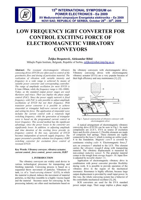
Fig.1. Typical construction <strong>of</strong> vibratory conveyer with<br />
electromagnetic drive<br />
A typical arrangement <strong>of</strong> electromagnetic vibratory<br />
conveying drive (EVCD) can be seen in Fig.1. Its main<br />
components are LCE-1, EVA as source <strong>of</strong> excitation<br />
<strong>for</strong>ce and flexible elements-2. Flexible elements are made<br />
<strong>of</strong> composite leaf springs. These elements are rigidly<br />
connected to the base-3, which is resting on rubber pads-<br />
4 to the foundation. Magnetic core-5 is covered by<br />
continuous winding coils- 6. Electromagnetic <strong>for</strong>ce f<br />
acts on armature-7 attached to the LCE. This element<br />
carries the vibratory trough-8 along with transporting<br />
material. The vibratory displacement is measured by<br />
non-contact inductive sensor- 9. The granular material<br />
comes to the trough from storage hopper- 10. Input f<strong>low</strong><br />
is adjusted by movable shutter- 11.<br />
Application <strong>of</strong> electromagnetic vibratory drive in<br />
combination with power <strong>converter</strong> provides flexibility<br />
during work. It is possible to provide operation <strong>of</strong> the<br />
vibratory drive in the region <strong>of</strong> the mechanical<br />
resonance. Resonance is highly efficient, because large<br />
output displacement is provided by small input power. In<br />
this way, the whole conveying system has a behavior <strong>of</strong><br />
the <strong>control</strong>lable mechanical oscillator [3], [4].<br />
SCR <strong>converter</strong>s are used <strong>for</strong> the EVA standard<br />
power output stage. Their usage implies a phase angle
<strong>control</strong> [4-6]. Firing angle varying provides the<br />
<strong>control</strong>led AC or DC injection current <strong>of</strong> EVA or<br />
<strong>control</strong>s his mechanical <strong>for</strong>ce. This <strong>for</strong>ce is squared<br />
function <strong>of</strong> current in EVA winding coils [3], [5-7].<br />
One type <strong>of</strong> this <strong>converter</strong>-unidirectional, with DC<br />
pulsing output current, using only one half period <strong>of</strong><br />
mains voltage. They are implemented with a one<br />
thyristor as shown in Fig.2 (a). In this case thyristor<br />
firing is achieved only in positive half wave as shown in<br />
Fig.3 (a). The output voltage (50Hz or 60Hz) is<br />
converted to pulsating DC current <strong>of</strong> EVA i.e. pulsating<br />
<strong>for</strong>ce <strong>of</strong> EVCD. In this way, generate vibrations <strong>of</strong><br />
discrete spectrum like in Fig.3, depending on the<br />
moment <strong>of</strong> thyristor firing.<br />
Fig.2. Power <strong>converter</strong> with phase angle <strong>control</strong> <strong>for</strong><br />
vibratory conveying <strong>control</strong>; (a)-unidirectional, (b)-<br />
bidirectional<br />
Another type power <strong>converter</strong>- bidirectional with<br />
AC output current, using full period <strong>of</strong> mains voltage.<br />
They are implemented with triacs or ant-parallel<br />
connection <strong>of</strong> thyristor <strong>for</strong> higher power application, as<br />
shown in Fig.2 (b).With these power <strong>converter</strong>s is the<br />
mains <strong>frequency</strong> 50Hz/60Hz converted to AC power<br />
supplied to the same <strong>frequency</strong> coil EVA as shown in<br />
Fig.3(b).<br />
Fig.3. PAC <strong>for</strong> vibratory conveying drive; EVA voltage and<br />
current; (a)-bidirectional mode, (b)-unidirectional mode<br />
Today is intensively working on implemented <strong>of</strong><br />
high-<strong>frequency</strong> (HF) power <strong>converter</strong>s <strong>for</strong> obtaining<br />
sinusoidal current in the EVA. As in the case <strong>of</strong> SCR can<br />
talk about on unidirectional and bidirectional <strong>converter</strong><br />
type, depending on whether there was DC pulsating or<br />
AC excitation <strong>of</strong> EVA. The generally accepted<br />
topologies are shown in Fig.4.<br />
Fig.4. Power <strong>converter</strong> switching topology <strong>for</strong> driving EVA;<br />
(a)- asymmetrical half bridge,(b)-symmetrical half bridge, (c)-<br />
full bridge<br />
The HF switching <strong>converter</strong>s, despite significant<br />
merits, have a shortcoming <strong>of</strong> having switching losses<br />
which become dominant at high frequencies. This<br />
reduces the efficiency <strong>of</strong> the EVCD and power losses in<br />
the <strong>converter</strong> are <strong>of</strong>ten higher than the power required <strong>for</strong><br />
maintaining the resonant oscillatory regime. This reduces<br />
considerably the efficiency <strong>of</strong> the whole system [9].<br />
By suitable way to <strong>control</strong> <strong>of</strong> EVCD it is possible<br />
to overcome this problem. In the present paper this is<br />
obtained by generating <strong>low</strong> <strong>frequency</strong> triangle current<br />
pulses <strong>of</strong> EVA. One possibility is to use half-bridge like<br />
in Fig.4 (a).<br />
2. MODELLING OF EVCD DYNAMICS<br />
Principle <strong>of</strong> amplitude-<strong>frequency</strong> <strong>control</strong> means<br />
actuating <strong>for</strong>ce is given on the block diagram in Fig.5. A<br />
high per<strong>for</strong>mance <strong>exciting</strong> <strong>for</strong>ce <strong>control</strong> <strong>of</strong> EVCD<br />
requires a detailed analysis <strong>of</strong> their electromagnetic and<br />
mechanical part.<br />
Fig.5. Principal block diagram <strong>of</strong> regulated EVCD<br />
2.1-Electromagnetic part<br />
Detailed electrical model <strong>of</strong> EVA is derived in [5]. It<br />
can be written as [10-13]:<br />
di ⎛∂L( y)<br />
dy ⎞<br />
Ly ( ) + ⎜ + R i=<br />
u<br />
dt ⎝ ∂y dt ⎠ ⎟ (1)<br />
1 ∂L( y)<br />
2<br />
f = i<br />
2 ∂y<br />
(2)<br />
where, R and L( y)<br />
denotes EVA coil electrical<br />
resistance and inductivity, and y , i , u denotes LCE<br />
position in relation to conveyer base, EVA coil current<br />
and EVA coil voltage respectively. Mechanical <strong>for</strong>ce<br />
f is produced by the electromagnet. According to Fig.5,<br />
EVA coil voltage u depends on <strong>control</strong> voltageu D<br />
:<br />
⎧ Vs, uD<br />
= 1∧Δ i > 0<br />
⎪<br />
u = ⎨− Vs, uD<br />
= 0∧Δ i
with Ly ( ) ≈ L0+ ( y−y0) ⋅∂L/ ∂ y y =<br />
. Now, equation (1) can be<br />
y<br />
approximated around<br />
0<br />
y = y 0 as:<br />
di dy ∂L<br />
L0 + R' i = u, R'<br />
= R+<br />
(4)<br />
dt dt ∂y y = y0<br />
where parameter R' , dependant on velocity dy/dt ,<br />
represents equivalent resistance. Pulses generated by<br />
<strong>control</strong> logic are short, so supposing that the equivalent<br />
time constant L 0 / R ' is much greater then pulse<br />
duration, we obtain Ri '
section.The influence <strong>of</strong> current reference changes and<br />
<strong>control</strong> logic signals at the entrance to the FF on the<br />
EVA current and output displacement are given in Fig.7.<br />
5. EXPERIMENTAL RESULTS<br />
The experimental results are obtained on real realized<br />
laboratory prototype <strong>of</strong> resonant EVCD at which the<br />
applied current <strong>control</strong> and high per<strong>for</strong>mance <strong>exciting</strong><br />
<strong>for</strong>ce <strong>control</strong>. The principle scheme <strong>of</strong> the realized<br />
system with IGBT power <strong>converter</strong> is given in Fig.10.<br />
Detailed description <strong>of</strong> this IGBT <strong>converter</strong> is given in<br />
[3]. It is experimentally observed the values <strong>of</strong> interest:<br />
EVA current- i(t) and output displacement <strong>of</strong> vibratory trough –<br />
y(t).<br />
On the oscilloscopic records in Fig.8. are shown the<br />
impact <strong>of</strong> changes in the duration <strong>of</strong> current pulse on the<br />
output displacement <strong>of</strong> vibratory trough at the resonant<br />
<strong>frequency</strong> f =45.5Hz and unchanged amplitude<br />
current<br />
I Mref<br />
rez<br />
=0.5A . At the stationary and unchanged<br />
resonance regime, change <strong>of</strong> current pulse duration <strong>for</strong><br />
about 33%, caused a nearly tw<strong>of</strong>old greater change in the<br />
value <strong>of</strong> the amplitude oscillation <strong>of</strong> the vibratory trough.<br />
On the Fig.9 are shown the load change<br />
compensation <strong>of</strong> EVCD and oscilloscopic records <strong>of</strong><br />
characteristic values (EVA current, EVA voltage and<br />
displacement <strong>of</strong> vibratory trough).<br />
Fig.7. The influence <strong>of</strong> refrence current change on the<br />
output displacement <strong>of</strong> EVCD; (a)-output displacement and<br />
EVA current, (b)-detail <strong>of</strong> interval I , (c)-detail <strong>of</strong> interval II<br />
In the simulation is set to the value <strong>of</strong> the resonant<br />
<strong>frequency</strong> <strong>of</strong> the mechanical system f rez =52Hz and period<br />
<strong>of</strong> driving pulses T=19.3ms d<br />
( f pob=52Hz).<br />
The simulations records <strong>of</strong> vibratory trough<br />
displacement- yt () and EVA current- it () in the case <strong>of</strong><br />
changing amplitude current reference are given on Fig.7<br />
(a). On the simulation records are marked two intervals<br />
<strong>of</strong> interest.<br />
These intervals are presented in detailed together<br />
with the corresponding <strong>control</strong> signals SET and RESET.<br />
The interval-I is given on the Fig.7 (a), while the<br />
interval-II is given on the Fig.7(c). In the first moment is<br />
established stationary regime with amplitude<br />
displacement value <strong>of</strong> Y m1=0.1mm<br />
i.e. vibratory width<br />
value <strong>of</strong> Y (p-p)1=0.2mm<br />
in which the amplitude <strong>of</strong> EVA<br />
current was I m1=280mA .In the moment <strong>of</strong> time t=2.5s is<br />
setting sudden increase <strong>of</strong> reference value <strong>of</strong> current<br />
half-wave <strong>for</strong>ms around 40%. As a result, there has been<br />
an increase in amplitude <strong>of</strong> the output displacement on<br />
the value Y m2 =0.2mm i.e. vibratory width value<br />
<strong>of</strong> Y (p-p)1=0.4mm. In addition to the current amplitude<br />
changes has been a change <strong>of</strong> time increase the value <strong>of</strong><br />
EVA current from value τ r1=0.64ms<br />
to<br />
value τ r1=1.70ms<br />
.These values actually represent the<br />
time interval between corresponding pulses SET and<br />
RESET <strong>of</strong> FF, as shown in Fig.7(b),(c).<br />
Fig.8. The influence <strong>of</strong> change EVA current duration on the<br />
output displacement;(a)-EVA current duration τ=3ms,(b)- EVA<br />
current duration τ=4ms; CH1- EVA current (0.2A/c),CH2-<br />
displacement (1mm/c).<br />
Fig.9. The load mass compensation <strong>of</strong> EVCD through<br />
changing <strong>frequency</strong> <strong>of</strong> EVA current, (a)-excitation <strong>frequency</strong><br />
f p1=f rez1=50Hz (b)- excitation <strong>frequency</strong> f p2 =f rez2 =41.5Hz ;<br />
CH1-EVA current (0.5A/c),CH2- displacement (2mm/c), CH3-EVA<br />
voltage (200V/c).<br />
The mass change was achieved with from<br />
m k0 =1.15kg to value m k1 = 1.65kg. Oscilloscopic<br />
records <strong>for</strong> mass load m k0<br />
(empty vibratory trough) are<br />
shown on Fig.9 (a). Oscilloscopic records <strong>for</strong> mass load<br />
m k1<br />
are shown on Fig.9 (b). The load change<br />
compensation and maintaining constant vibration<br />
amplitude <strong>of</strong> vibratory trough is achieved by changing<br />
the <strong>frequency</strong> <strong>of</strong> EVA current (from<br />
f rez1=50Hzto<br />
f rez2 =41.5Hz) at same value <strong>of</strong> time<br />
duration τ=4ms .
Fig.10. Principal diagram <strong>of</strong> implemented IGBT <strong>converter</strong> <strong>for</strong> current <strong>control</strong> <strong>of</strong> EVCD<br />
The mass change was achieved with from m k0 =1.15kg<br />
to value mk1 = 1.65kg. Oscilloscopic records <strong>for</strong> mass<br />
load<br />
m k0<br />
(empty vibratory trough) are shown on Fig.9<br />
(a). Oscilloscopic records <strong>for</strong> mass load<br />
m k1<br />
are shown<br />
on Fig.9 (b). The load change compensation and<br />
maintaining constant vibration amplitude <strong>of</strong> vibratory<br />
trough is achieved by changing the <strong>frequency</strong> <strong>of</strong> EVA<br />
current (from f rez1=50Hzto f rez2 =41.5Hz) at same value<br />
<strong>of</strong> time duration τ=4ms .<br />
6. CONCLUSION<br />
The paper presented a possible solution to excitation<br />
<strong>for</strong>ce <strong>control</strong> <strong>of</strong> EVCD. Presented simulation and<br />
experimental results showed that current <strong>control</strong> <strong>of</strong> EVA<br />
is a very effective way to amplitude and <strong>frequency</strong><br />
<strong>control</strong> <strong>of</strong> resonant EVCD. Resonant regime is very<br />
important from the aspect <strong>of</strong> minimizing energy<br />
consumption <strong>of</strong> the entire EVCD.<br />
The current <strong>control</strong> is achieved such that a<br />
mechanical system is <strong>control</strong>lable mechanical oscillator,<br />
independent <strong>of</strong> the supply network <strong>frequency</strong>, which was<br />
achieved a significant improvement compared to the<br />
thyristors and triacs drives.<br />
7. REFERENCES<br />
[1] H.G.Cock ,“Vibratory Feeders“-PHILIPS Technical<br />
Review, Vol.24, May 1975,pp.84-95.<br />
[2] P.U.Frei, “An Intelligent Vibratory Conveyor <strong>for</strong> the<br />
Individual Object Transportation in Two Dimensions”,<br />
Proceedings <strong>of</strong> the 2002 IEEE/RSJ, Intl. Conference on<br />
Intelligent Robots and Systems, EPFL, Lausanne,<br />
Switzerland, October 2002, pp.1832-1837.<br />
[3] Z.Despotovic and Z.Stojiljkovic, ”Power Converter<br />
Control Circuits <strong>for</strong> Two-Mass Vibratory Conveying System<br />
with Electromagnetic Drive: Simulations and Experimental<br />
Results”, IEEE Transaction on Industrial Electronics,<br />
Vol.54, Issue I, Februar 2007,pp.453-466.<br />
[4] T.Doi, K.Yoshida, Y.Tamai, K.Kono, K.Naito, T.Ono,<br />
“Modeling and Feedback Control <strong>for</strong> Vibratory Feeder<br />
<strong>of</strong> Electromagnetic Type”, Journal <strong>of</strong> Robotics and<br />
Mechatronics , Vol.11, No.5, June 1999, pp. 563-572.<br />
[5] N.Barjamović,“Tiristori u sistemima za doziranje rasutih<br />
materijala”, II simpozijum Energetska elektronika – Ee<br />
’75, Beograd (YU), Oktobar 1975, pp.334-348.<br />
[6] T.Doi, K.Yoshida, Y.Tamai, K.Kono, K.Naito, T.Ono,<br />
“Feedback Control <strong>for</strong> Electromagnetic Vibration<br />
Feeder”, JSME International Journal, Series C, Vol.44,<br />
No.1, 2001, pp. 44-52.<br />
[7] Ž.Despotović, M.Jovanović, Z.Stojiljković, “Tiristorski<br />
pretvarač za pogon elektromagnetnih vibratora”, X<br />
simpozijum Energetska elektronika – Ee ’99, N.Sad<br />
(YU), Oktobar 1999, pp.150-156.<br />
[8] Z.Despotovic, Z. and Z. Stojiljkovic, ”PSPICE<br />
Simulation <strong>of</strong> Two Mass Vibratory Conveying System<br />
with Electromagnetic Drive” , PROCEEDINGS <strong>of</strong><br />
International Conference EUROCON 2009-“Computer<br />
as a tool” , Belgrade 21.XI.-24.XI.2005, Vol. II,<br />
pp.1509-1512.<br />
[9] Z.Despotovic, Z.Stojiljkovic, “A Realization AC/DC<br />
Transistor Power Converter <strong>for</strong> Driving Electromagnetic<br />
Vibratory Conveyors”, PROCEEDINGS <strong>of</strong> the V<br />
Symposium <strong>of</strong> Industrial Electronics-INDEL, Banja<br />
Luka, 11-13.IX.2004, Vol. T2A, pp.34-40.<br />
[10] V.Gourishankar, D.H.Kelly, “Electromehanical energy<br />
conversion”, Billing and Sons Ltd., Guld<strong>for</strong>d &<br />
London, London, 1973.<br />
[11] Z.Despotovic,“Mathematical model <strong>of</strong> electromagnetic<br />
vibratory actuator”, PROCEEDINGS <strong>of</strong> the XII<br />
International Symposium <strong>of</strong> the Power Electronics,<br />
N.Sad 5.XI-7.XI.2003, Vol.T3-3.2, pp.1-5(In Serbian).<br />
[12] S.Seely, Electromechanical energy conversion”,<br />
McGraw-HILL Book Company INC., New York, 1962.<br />
[13] Z.Despotovic, M.Pesko, “Mathematical Model <strong>of</strong><br />
Vibratory Feeder Drive with Electromagnetic Vibratory<br />
Actuator”, PROCEEDINGS <strong>of</strong> the XLVIII Conference<br />
ETRAN, Cacak, 8-13.06.2004, Vol.I, pp.276-279.<br />
[14] P.Wolfsteiner, F.Pfeiffer, “Dynamics <strong>of</strong> a vibratory<br />
feeder”, PROCEEDINGS <strong>of</strong> DETC '97, ASME Design<br />
Engineering Technical Conferences, Sacramento,<br />
Cali<strong>for</strong>nia, DETC97/VIB-3905,Sept.14-17,1997, pp.1-9.<br />
[15] T.Doi, K.Yoshida, Y.Tamai, K.Kono, K.Naito,T. Ono<br />
“Feedback Control <strong>for</strong> Vibratory Feeder <strong>of</strong><br />
Electromagnetic Type”, Proc. ICAM’98, 1998, pp. 849-<br />
854.