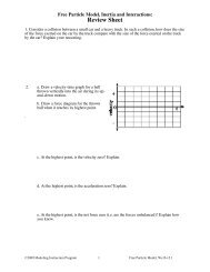
Summary reading for the Electric Circuits Model
Summary reading for the Electric Circuits Model
Summary reading for the Electric Circuits Model

You also want an ePaper? Increase the reach of your titles
YUMPU automatically turns print PDFs into web optimized ePapers that Google loves.
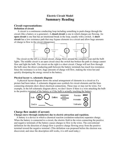
<strong>Electric</strong> Circuit <strong>Model</strong><br />
<strong>Summary</strong> Reading<br />
Circuit representations:<br />
Definition of circuit<br />
A circuit is a continuous conducting loop including something to push charge through <strong>the</strong><br />
circuit (like a battery or a generator). A closed circuit is one in which charges are flowing. An<br />
open circuit is one that has an intentional break in <strong>the</strong> loop, usually with a switch. A short<br />
circuit has a low resistance path that may bypass elements in a circuit and allow huge amounts<br />
of charge to flow in <strong>the</strong> circuit (dangerous).<br />
The circuit on <strong>the</strong> left is a closed circuit; charge flows around <strong>the</strong> complete loop and <strong>the</strong> bulb<br />
lights. The middle circuit is an open circuit since <strong>the</strong> switch has broken <strong>the</strong> path so charge cannot<br />
flow and light <strong>the</strong> bulb. The circuit on <strong>the</strong> right is a short circuit. Charge will not flow through<br />
<strong>the</strong> bulb since <strong>the</strong> direct conducting path between <strong>the</strong> battery terminals has much less resistance.<br />
Since <strong>the</strong> resistance is so low, huge amounts of charge will flow, making <strong>the</strong> wires hot and<br />
quickly dissipating <strong>the</strong> energy stored in <strong>the</strong> battery.<br />
Physical layout vs. schematic diagram<br />
A physical layout diagram shows <strong>the</strong> actual arrangement of elements in a circuit as if a<br />
picture had been taken. A schematic diagram uses symbols <strong>for</strong> circuit elements and <strong>the</strong> lines<br />
connecting elements show direct electrical connections. These may or may not be wires. For<br />
example, in <strong>the</strong> left schematic diagram above, we don’t know if <strong>the</strong>re is a wire attaching <strong>the</strong> bulb<br />
to <strong>the</strong> positive terminal of <strong>the</strong> battery or if <strong>the</strong> bulb is actually touching <strong>the</strong> battery.<br />
Charge flow model: (Current)<br />
Charges move through conductors due to electric attraction and repulsion.<br />
A battery is a device in which a chemical reaction (oxidation-reduction) separates charge.<br />
When <strong>the</strong> battery is connected to a circuit, <strong>the</strong> electric field in <strong>the</strong> wires connecting <strong>the</strong> positive<br />
and negative terminals of <strong>the</strong> battery causes charges to flow in <strong>the</strong> wires. The conventional<br />
definition <strong>for</strong> <strong>the</strong> direction of charge flow is positive charge flowing away from <strong>the</strong> positive<br />
terminal toward <strong>the</strong> negative terminal. (This definition was proposed be<strong>for</strong>e <strong>the</strong> electron was<br />
discovered, and since <strong>the</strong> description still works, it is still used today.)
Charges do not get “used up” in a circuit<br />
Charges are not created or destroyed (conservation of charge) so it is important to picture <strong>the</strong>m<br />
as little particle-like objects that flow in and out of circuit devices. The charges <strong>the</strong>mselves do<br />
not make bulbs light. We will see later that it is <strong>the</strong> energy that each charge carries that lights <strong>the</strong><br />
bulb.<br />
Adding obstacles inhibits <strong>the</strong> flow of charge (series circuits)<br />
A series circuit consists of a single conducting loop. In a series circuit <strong>the</strong> charge flows<br />
equally through each circuit element, and equally through each wire.<br />
In a series circuit, when more obstacles are added it is harder <strong>for</strong> charges to flow, and as a<br />
result <strong>the</strong> flow rate decreases throughout <strong>the</strong> circuit. Each obstacle (i.e. a light bulb) resists <strong>the</strong><br />
flow of charge and has a measurable property called resistance. Charge flow is inversely<br />
proportional to <strong>the</strong> resistance of <strong>the</strong> circuit.<br />
In <strong>the</strong> three series circuits above, we can see <strong>the</strong> inverse relation between charge flow and<br />
resistance. The left circuit is our reference circuit. The middle circuit has twice <strong>the</strong> resistance of<br />
<strong>the</strong> left circuit, (assuming <strong>the</strong> bulbs have identical resistance) <strong>the</strong>re<strong>for</strong>e <strong>the</strong> middle circuit has<br />
only half <strong>the</strong> charge flow of <strong>the</strong> left circuit. The circuit on <strong>the</strong> right has three times <strong>the</strong> resistance<br />
of <strong>the</strong> left circuit and has one-third <strong>the</strong> charge flow from <strong>the</strong> battery and throughout <strong>the</strong> circuit.<br />
Adding pathways allows more charge to flow (parallel circuits)<br />
A parallel circuit consists of more than one conducting loop. This means that <strong>the</strong> flow of<br />
charge is not equal everywhere in <strong>the</strong> circuit, since <strong>the</strong>re will be junctions where <strong>the</strong> charge flow<br />
splits to take different paths around <strong>the</strong> circuit.<br />
Note that <strong>the</strong> parallel circuits above are identical since <strong>the</strong>y both show <strong>the</strong> same electrical<br />
connections. Both show that <strong>the</strong> charge flowing from <strong>the</strong> battery splits, some travels through<br />
each bulb, <strong>the</strong> charges rejoin and flow back into <strong>the</strong> opposite terminal of <strong>the</strong> battery.<br />
Adding additional pathways (branches or loops) to <strong>the</strong> circuit makes it easier <strong>for</strong> charge to<br />
flow since <strong>the</strong>re are more ways <strong>for</strong> charge to flow around <strong>the</strong> circuit. Adding branches increases<br />
<strong>the</strong> charge flow from <strong>the</strong> battery and decreases <strong>the</strong> overall resistance of <strong>the</strong> circuit. In parallel<br />
circuits, each branch is also independent of one ano<strong>the</strong>r. Any branch can be turned on or off<br />
without affecting <strong>the</strong> operation of <strong>the</strong> o<strong>the</strong>r branches. (This is why your house is wired in<br />
parallel.)
In all three parallel circuits above, <strong>the</strong> flow of charge through each branch is identical. The<br />
flow of charge from <strong>the</strong> battery is not identical. If <strong>the</strong> flow in <strong>the</strong> left circuit is X, <strong>the</strong>n <strong>the</strong> flow<br />
from (and into) <strong>the</strong> battery in <strong>the</strong> middle circuit is 2X. In <strong>the</strong> right circuit <strong>the</strong> flow would be 3X,<br />
assuming that <strong>the</strong> bulbs have identical resistance.<br />
Quantitative combinations of resistors<br />
The squiggly line in <strong>the</strong> schematics below represents a generic resistor (like a light bulb or<br />
heater). The unit <strong>for</strong> electrical resistance is <strong>the</strong> Ohm, represented by <strong>the</strong> Greek letter omega, Ω .<br />
In series circuits, <strong>the</strong> total resistance is additive: R total = R 1 + R 2 + R 3 + . . .<br />
Each additional resistor in <strong>the</strong> series makes charge flow more difficult. In <strong>the</strong> series circuit<br />
shown above, <strong>the</strong> total resistance equals <strong>the</strong> sum of <strong>the</strong> two resistances, or 10 Ω.<br />
In parallel circuits, <strong>the</strong> total conductivity is additive: (Conductivity is <strong>the</strong> reciprocal of<br />
resistivity.) 1/R total = 1/R 1 + 1/R 2 + 1/R 3 . . .<br />
Each additional pathway decreases <strong>the</strong> resistance and makes charge flow easier. In <strong>the</strong> parallel<br />
circuit shown above, <strong>the</strong> total resistance equals <strong>the</strong> reciprocal of <strong>the</strong> sum of <strong>the</strong> reciprocals of <strong>the</strong><br />
branch resistances, or 2.5 Ω.<br />
Current (in Amperes) is defined as <strong>the</strong> number of charges (in Coulombs) flowing past a<br />
point in <strong>the</strong> circuit each second<br />
<strong>Electric</strong>al current is <strong>the</strong> fancy name <strong>for</strong> "rate of flow of charge". One Coulomb of charges<br />
passing a point in a circuit each second is one Ampere of current (one Coulomb is 6.25 x 10 18<br />
charges). The common abbreviation <strong>for</strong> current in equations is <strong>the</strong> capital letter "I" to minimize<br />
confusion with Coulomb, charge, and capacitance. The unit <strong>for</strong> current, Ampere, is abbreviated<br />
"A".<br />
Junction rule: (conservation of charge)<br />
In parallel circuits <strong>the</strong>re are junctions where <strong>the</strong> charge flow splits or rejoins. The number of<br />
charges flowing into a junction must equal <strong>the</strong> number flowing out of <strong>the</strong> junction. In o<strong>the</strong>r<br />
words, <strong>the</strong> sum of <strong>the</strong> currents entering <strong>the</strong> junction must equal <strong>the</strong> sum of <strong>the</strong> currents leaving<br />
<strong>the</strong> junction.<br />
The resistance of each branch determines how <strong>the</strong> current will split when it gets to a junction.<br />
More current will flow along <strong>the</strong> branch with less resistance.
In <strong>the</strong> circuit above, <strong>the</strong> charges will split unevenly at <strong>the</strong> junction. Twice as many charges<br />
flow through <strong>the</strong> single bulb branch as flow though <strong>the</strong> two-bulb branch. For example, 3<br />
Amperes of current might flow out of <strong>the</strong> battery. The current would split at <strong>the</strong> junction so that<br />
2 A travels through <strong>the</strong> single bulb and 1 A would flow through <strong>the</strong> two-bulb branch. The current<br />
would rejoin at <strong>the</strong> o<strong>the</strong>r junction and 3 A would flow back into <strong>the</strong> battery.<br />
<strong>Electric</strong> Field Energy model: (Potential)<br />
Energy stored in <strong>the</strong> electric field is transferred to circuit resistors as charges move<br />
through <strong>the</strong> field.<br />
In order <strong>for</strong> charges to move through a circuit, energy is required. The energy ultimately<br />
comes from <strong>the</strong> chemical reactions in <strong>the</strong> battery that separate charges. The separated charges<br />
store energy in <strong>the</strong> electric field in <strong>the</strong> circuit. As charges move through <strong>the</strong> field, <strong>the</strong> field loses<br />
energy, which is continually replaced by <strong>the</strong> battery until <strong>the</strong> chemical reactions in <strong>the</strong> battery<br />
reach completion. Energy that <strong>the</strong> field loses is transferred to electrical devices in <strong>the</strong> circuit<br />
(bulbs, resistors, motors, etc . . .) The field loses very little energy <strong>for</strong> each charge that passes<br />
through connecting wires because <strong>the</strong> resistance in connecting wires is so small. The field loses<br />
much more energy <strong>for</strong> each charge that passes through resistive circuit elements.<br />
<strong>Electric</strong> Potential tells <strong>the</strong> “energy density” of <strong>the</strong> electric field in Joules per Coulomb at a<br />
point in <strong>the</strong> circuit.<br />
For example, <strong>the</strong> negative terminal of a battery has an electric potential of zero: positive<br />
charges at <strong>the</strong> negative terminal of <strong>the</strong> battery will not enter <strong>the</strong> circuit. Positive charges at <strong>the</strong><br />
positive terminal of <strong>the</strong> battery are at a high potential, that is, <strong>the</strong> field can lose lots of energy as<br />
<strong>the</strong> positive charges leave <strong>the</strong> positive battery terminal and pass through <strong>the</strong> circuit. The larger<br />
<strong>the</strong> potential difference between <strong>the</strong> terminals of <strong>the</strong> battery, <strong>the</strong> greater <strong>the</strong> amount of energy <strong>the</strong><br />
field will lose <strong>for</strong> each Coulomb of charge that passes through <strong>the</strong> circuit.<br />
Potential difference, or Voltage, is <strong>the</strong> number of Joules of electric field energy required to<br />
move one Coulomb of charge between two points in a circuit<br />
Measuring a potential difference between two points in a circuit implies <strong>the</strong> existence of an<br />
electric field. As <strong>the</strong> field moves charges, <strong>the</strong> field loses energy. For example, a 1.5 Volt battery<br />
supplies 1.5 Joules of energy to <strong>the</strong> electric field <strong>for</strong> each Coulomb of charge that travels through<br />
<strong>the</strong> circuit. In a series circuit with two identical bulbs connected to a 1.5 volt battery, <strong>the</strong><br />
potential difference across each lightbulb is 0.75 V. In o<strong>the</strong>r words, as charges pass through <strong>the</strong><br />
fields in <strong>the</strong> bulbs, 0.75 Joules of energy will be transferred to each lightbulb from <strong>the</strong> field <strong>for</strong><br />
every Coulomb of charge that passes through <strong>the</strong>m.
Increasing <strong>the</strong> potential difference increases <strong>the</strong> flow of charge: (current is proportional to<br />
voltage)<br />
When batteries are connected in series, <strong>the</strong>re is a larger potential difference than when a single<br />
battery is used. The resulting electric field through <strong>the</strong> circuit is stronger, causing more charges<br />
to move.<br />
The circuit on <strong>the</strong> left will light <strong>the</strong> bulb. In <strong>the</strong> middle circuit, <strong>the</strong>re are two batteries. The<br />
voltage is doubled and <strong>the</strong> current will double. The circuit on <strong>the</strong> left has triple <strong>the</strong> voltage of <strong>the</strong><br />
circuit on <strong>the</strong> left, and three times as many charges will flow through <strong>the</strong> bulb in <strong>the</strong> right circuit<br />
each second. The current is directly proportional to <strong>the</strong> voltage.<br />
Loop rule: <strong>the</strong> battery voltage minus <strong>the</strong> voltage drops around a circuit loop equals zero<br />
(conservation of energy)<br />
The series circuit on <strong>the</strong> left has a 12 Volt battery. The field will lose a total of 12 Joules of<br />
energy <strong>for</strong> each Coulomb of charge that passes through <strong>the</strong> circuit, transferring 6 Joules of<br />
energy to <strong>the</strong> first resistor and 6 Joules of energy to <strong>the</strong> second resistor as one Coulomb of charge<br />
passes through <strong>the</strong>m. So <strong>the</strong> voltage drop across each resistor is 6 Volts. The loop rule is satisfied<br />
by 12 V = 6 V + 6 V.<br />
In <strong>the</strong> parallel circuit on <strong>the</strong> right, both resistors have direct electrical connections to <strong>the</strong><br />
battery, and both resistors are in <strong>the</strong>ir own loop. The voltage of <strong>the</strong> battery has to be equal to <strong>the</strong><br />
voltage drop across each resistor, regardless of its resistance, since <strong>the</strong> field will lose 12 Joules of<br />
energy <strong>for</strong> every Coulomb of charge passing through a branch. Here we use <strong>the</strong> loop rule twice:<br />
12V across <strong>the</strong> battery = 12 V across <strong>the</strong> left resistor and 12V across <strong>the</strong> battery = 12 V across<br />
<strong>the</strong> right resistor.<br />
Now we will look at <strong>the</strong> loop rule when <strong>the</strong> resistors do not have equal values. In <strong>the</strong> series<br />
circuit, <strong>the</strong> field will lose twice as much energy as charges pass through <strong>the</strong> 10 Ohm resistor as is<br />
lost as charges pass through <strong>the</strong> 5 Ohm resistor. Consequently, <strong>for</strong> every charge that passes<br />
through <strong>the</strong> circuit, one third of <strong>the</strong> field’s energy will be transferred to <strong>the</strong> 5 Ohm resistor and<br />
two-thirds to <strong>the</strong> 10 Ohm resistor. The loop rule is satisfied by 12 V across <strong>the</strong> battery = 4 V<br />
drop across <strong>the</strong> 5 Ohm resistor and an 8 Ohm drop across <strong>the</strong> 10 Ohm resistor.<br />
In <strong>the</strong> parallel circuit, <strong>the</strong> voltage drop across each resistor is still equal to <strong>the</strong> battery voltage.<br />
In this case, <strong>the</strong> current will not be <strong>the</strong> same in each branch, but <strong>the</strong> amount of energy <strong>the</strong> field<br />
will lose <strong>for</strong> every Coulomb of charge passing through <strong>the</strong> branches is <strong>the</strong> same.
Ohm's law: Voltage = Current x Resistance<br />
In <strong>the</strong> previous sections we have established that current is inversely proportional to resistance<br />
and current is directly proportional to voltage. Combining <strong>the</strong>se relations we get current =<br />
voltage/ resistance. Solving <strong>for</strong> resistance: resistance = voltage/current. Solving <strong>for</strong> voltage,<br />
voltage = current x resistance, or V = IR.<br />
Power is <strong>the</strong> amount of energy transferred each second: Power (in watts) = Voltage x<br />
Current<br />
The actual brightness of a light bulb depends on <strong>the</strong> number of charges flowing through <strong>the</strong><br />
bulb each second (current), as well as <strong>the</strong> energy lost by <strong>the</strong> field per charge (voltage). The<br />
product of current and voltage is a rate of energy transfer, power.<br />
Example of energy transfer (power) in series and parallel circuits:<br />
In <strong>the</strong> series circuit, <strong>the</strong> current is <strong>the</strong> same through both resistors, however <strong>the</strong> voltage drop is<br />
not. Using Ohm’s law, we can determine that <strong>the</strong> current in <strong>the</strong> circuit is I = V/R = 12 V/15 Ω =<br />
0.8 A. So <strong>the</strong> rate of electric field energy transferred to <strong>the</strong> 5 Ohm resistor is P = IV = 0.8 A x 4<br />
V = 3.2 Watts. The energy transfer rate to <strong>the</strong> 10 Ohm resistor is P = IV = 0.8 A x 8 V = 6.4<br />
Watts. Note that if <strong>the</strong> resistors were light bulbs, <strong>the</strong> 10 Ohm resistor would correspond to <strong>the</strong><br />
brighter bulb.<br />
In <strong>the</strong> parallel circuit, <strong>the</strong> voltage is <strong>the</strong> same across each branch. The current flowing through<br />
<strong>the</strong> 5 Ohm branch is V/R = 2.4 A, more than <strong>the</strong> current flowing in <strong>the</strong> 10 Ohm branch, V/R =<br />
1.2A. So <strong>the</strong> energy transferred to <strong>the</strong> 5 Ohm resistor is P = IV = 2.4 A x 12 V = 28.8 Watts and<br />
<strong>the</strong> energy transferred by <strong>the</strong> 10 Ohm resistor is P = IV = 1.2 A x 12 V = 14.4 Watts. Note that in<br />
this case, <strong>the</strong> 5 Ohm resistor would correspond to <strong>the</strong> brighter bulb.