Sample problems Chap 20 Cutnell.pdf - DrJJ
Sample problems Chap 20 Cutnell.pdf - DrJJ
Sample problems Chap 20 Cutnell.pdf - DrJJ

Create successful ePaper yourself
Turn your PDF publications into a flip-book with our unique Google optimized e-Paper software.
<strong>Sample</strong>s of conceptual and analytical/numerical questions from chap <strong>20</strong>, C&J, 7E<br />
CHAPTER <strong>20</strong> CIRCUITS<br />
CONCEPTUAL QUESTIONS<br />
<strong>Cutnell</strong> & Johnson 7E<br />
2. When an incandescent light bulb is turned on, the tungsten filament becomes white hot.<br />
The temperature coefficient of resistivity for tungsten is a positive number. What happens to<br />
the power delivered to the bulb as the filament heats up Does the power increase, remain the<br />
same, or decrease Justify your answer.<br />
2. REASONING AND SOLUTION When an incandescent light bulb is turned on, the<br />
tungsten filament becomes white hot. Since the voltage is constant, the power delivered<br />
to the light bulb is given by Equation <strong>20</strong>.6c: P = V 2 / R . From Equation <strong>20</strong>.5,<br />
R = R0[1 + α( T − T0)]<br />
, where α is the temperature coefficient of resistivity and is a<br />
positive number. Thus, as the filament temperature increases, the resistance of the wire<br />
increases, and as the filament heats up, the power delivered to the bulb decreases.<br />
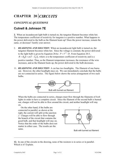
11. REASONING AND SOLUTION A car has two headlights. The filament of one burns<br />
out. However, the other headlight stays on. We can immediately conclude that the bulbs<br />
are not connected in series. The figure below shows the series arrangement of two such<br />
bulbs.<br />
Bulb with burned out filament<br />
When the bulbs are connected in series, charges must flow through the filaments of both<br />
lights in order to have a complete circuit. Since the filament of the second bulb is burned<br />
out, charges will not be able to flow around the circuit, and neither headlight will stay<br />
on.<br />
On the other hand, if the bulbs are<br />
J<br />
connected in parallel, as shown at the<br />
right, the current will split at the junction<br />
J. Charges will be able to flow through<br />
the branch of the circuit that contains the<br />
good bulb, and that headlight will stay on.<br />
Notice that the order of the bulbs does not<br />
matter in either case. The results are the<br />
same.<br />
Bulb with burned out filament<br />
__________________________________________________________________________________________<br />
12. In one of the circuits in the drawing, none of the resistors is in series or in parallel.<br />
Which is it Explain.<br />
Compiled by <strong>DrJJ</strong> Page 1 of 12 8/24/<strong>20</strong>06
<strong>Sample</strong>s of conceptual and analytical/numerical questions from chap <strong>20</strong>, C&J, 7E<br />
12. REASONING AND SOLUTION When two or more circuit elements are connected in<br />
series, they are connected such that the same electric current flows through each element.<br />
When two or more circuit elements are connected in parallel, they are connected such<br />
that the same voltage is applied across each element.<br />
The circuit in Figure (a) can be shown to be a combination of series and parallel<br />
arrangements of resistors. The circuit can be redrawn as shown in the following<br />
drawing.<br />
2 3<br />
3<br />
4<br />
2<br />
4<br />
5<br />
7<br />
5<br />
7<br />
1<br />
6<br />
8<br />
6<br />
8<br />
1<br />
We can see in the redrawn figure that the current through resistors 2 and 3 is the same;<br />
therefore, resistors 2 and 3 are in series and can be represented by an equivalent<br />
resistance 23 as shown in the following drawing.<br />
2 3<br />
4<br />
23<br />
4<br />
234<br />
5<br />
7<br />
5<br />
7<br />
5<br />
7<br />
6<br />
8<br />
6<br />
8<br />
6<br />
8<br />
1<br />
1<br />
1<br />
Compiled by <strong>DrJJ</strong> Page 2 of 12 8/24/<strong>20</strong>06
<strong>Sample</strong>s of conceptual and analytical/numerical questions from chap <strong>20</strong>, C&J, 7E<br />
The voltage across resistance 23 and resistor 4 is the same, so these two resistances are<br />
in parallel; they can be represented by an equivalent resistance 234. The current through<br />
resistance 234 is the same as that through resistor 7, so resistance 234 is in series with<br />
resistor 7; they can be represented by an equivalent resistance 2347 as shown in the<br />
following figure.<br />
2347<br />
23475<br />
234758<br />
5<br />
6<br />
8<br />
1<br />
6<br />
8<br />
1<br />
6<br />
1<br />
The voltage across 2347 is the same as that across resistor 5; therefore, resistance 2347 is<br />
in parallel with resistor 5. They can be represented by an equivalent resistance 23475.<br />
Similarly, resistance 23475 is in series with resistor 8, giving an equivalent resistance<br />
234758. Resistance 234758 is in parallel with resistor 6, giving an equivalent resistance<br />
2347586.<br />
Finally, the current through resistor 1 and<br />
resistance 2347586 is the same, so they<br />
are in series as shown at the right.<br />
1<br />
2347586<br />
The circuit in Figure (b) can also be shown to be a combination of series and parallel<br />
arrangements of resistors. Since both ends of resistors 2 and 3 are connected, the voltage<br />
across resistors 2 and 3 is the same. The same statement can be made for resistors 4 and<br />
5, and resistors 6 and 7. Therefore, resistor 2 is in parallel with the resistor 3 to give an<br />
equivalent resistance labeled 23. Resistor 4 is in parallel with resistor 5 to give an<br />
equivalent resistance 45, and resistor 6 is in parallel with resistor 7 to give an equivalent<br />
resistance 67. From the right-hand portion of the drawing below, it is clear that the<br />
resistances 23, 45, and 67 are in series with resistor 1.<br />
2<br />
4<br />
6<br />
23 45 67<br />
1<br />
3<br />
5<br />
7<br />
1<br />
Compiled by <strong>DrJJ</strong> Page 3 of 12 8/24/<strong>20</strong>06
<strong>Sample</strong>s of conceptual and analytical/numerical questions from chap <strong>20</strong>, C&J, 7E<br />
The drawing at the right shows the circuit<br />
1 2<br />
in Figure (c). No such simplifying<br />
arguments can be made for this circuit.<br />
No two resistors carry the same current;<br />
3<br />
thus, no two of the resistors are in series.<br />
Furthermore, no two resistors have the<br />
5<br />
4<br />
same voltage applied across them; thus,<br />
no two of the resistors are in parallel.<br />
Circuit (c) contains resistors that are<br />
neither in series nor in parallel.<br />
__________________________________________________________________________________________<br />
16. A proton and an electron are released from rest at the midpoint between the plates of a<br />
charged parallel plate capacitor. Except for these particles, nothing else is between the plates.<br />
Ignore the attraction between the proton and the electron, and decide which particle strikes a<br />
capacitor plate first. Why<br />
16. REASONING AND SOLUTION Since both particles are released from rest, their<br />
initial kinetic energies are zero. They both have electric potential energy by virtue of<br />
their respective positions in the electric field between the plates. Since the particles are<br />
oppositely charged, they move in opposite directions toward opposite plates of the<br />
capacitor. As they move toward the plates, the particles gain kinetic energy and lose<br />
potential energy. Using (EPE) 0<br />
and (EPE) f<br />
to denote the initial and final electric<br />
potential energies of the particle, respectively, we find from energy conservation that<br />
2<br />
( EPE) =<br />
1<br />
m v + ( EPE)<br />
The final speed of each particle is given by<br />
0 2 particle f<br />
f<br />
v<br />
f<br />
=<br />
( ) − ( )<br />
2⎡<br />
⎣<br />
EPE EPE<br />
m<br />
0 f<br />
particle<br />
⎤<br />
⎦<br />
Since both particles travel through the same distance between the plates of the capacitor,<br />
the change in the electric potential energy is the same for both particles. Since the mass<br />
of the electron is smaller than the mass of the proton, the final speed of the electron will<br />
be greater than that of the proton. Therefore, the electron travels faster than the proton as<br />
the particles move toward the respective plates. The electron, therefore, strikes the<br />
capacitor plate first.<br />
__________________________________________________________________________________________<br />
CHAPTER <strong>20</strong> CIRCUITS<br />
<strong>Sample</strong>s of solutions to Problems from chapter <strong>20</strong> <strong>Cutnell</strong><br />
& Johnson 7E<br />
Compiled by <strong>DrJJ</strong> Page 4 of 12 8/24/<strong>20</strong>06
<strong>Sample</strong>s of conceptual and analytical/numerical questions from chap <strong>20</strong>, C&J, 7E<br />
2. A defibrillator is used during a heart attack to restore the heart to its normal beating<br />
pattern (see Section 19.5). A defibrillator passes 18 A of current through the torso of a person<br />
in 2.0 ms. (a) How much charge moves during this time (b) How many electrons pass<br />
through the wires connected to the patient<br />
2. REASONING The current I is defined in Equation <strong>20</strong>.1 as the amount of charge ∆q<br />
per unit of time ∆t that flows in a wire. Therefore, the amount of charge is the product of the<br />
current and the time interval. The number of electrons is equal to the charge that flows<br />
divided by the magnitude of the charge on an electron.<br />
SOLUTION<br />
a. The amount of charge that flows is<br />
−<br />
( )( )<br />
3 −2<br />
∆ q = I∆ t = 18 A 2.0 × 10 s = 3.6 × 10 C<br />
b. The number of electrons N is equal to the amount of charge divided by e, the magnitude of<br />
the charge on an electron.<br />
−2<br />
∆q<br />
3.6 × 10 C<br />
17<br />
N = = = 2.3 × 10<br />
−19<br />
e 1.60 × 10 C<br />
___________________________________________________________________________<br />
8. A car battery has a rating of 2<strong>20</strong> ampere · hours (A · h). This rating is one indication of the<br />
total charge that the battery can provide to a circuit before failing. (a) What is the total charge<br />
(in coulombs) that this battery can provide (b) Determine the maximum current that the<br />
battery can provide for 38 minutes.<br />
8. REASONING AND SOLUTION<br />
a. The total charge that can be delivered is<br />
⎛3600 s ⎞<br />
5<br />
∆ q = (2<strong>20</strong> A ⋅ h) ⎜ ⎟= 7.9×<br />
10 C<br />
⎝ 1 h ⎠<br />
b. The maximum current is<br />
2<strong>20</strong> A ⋅ h<br />
I = = 350 A<br />
⎛ 1 hr ⎞<br />
(38 min) ⎜ ⎟<br />
⎝60 min ⎠<br />
___________________________________________________________________________<br />
13. ssm www Two wires have the same length and the same resistance. One is made from<br />
aluminum and the other from copper. Obtain the ratio of the cross-sectional area of the<br />
aluminum wire to that of the copper wire.<br />
13. REASONING The resistance of a metal wire of length L, cross-sectional area A and<br />
resistivity ρ is given by Equation <strong>20</strong>.3: R = ρL/<br />
A. Solving for A, we have A= ρL/<br />
R.<br />
We can use this expression to find the ratio of the cross-sectional area of the aluminum wire<br />
to that of the copper wire.<br />
Compiled by <strong>DrJJ</strong> Page 5 of 12 8/24/<strong>20</strong>06
<strong>Sample</strong>s of conceptual and analytical/numerical questions from chap <strong>20</strong>, C&J, 7E<br />
SOLUTION Forming the ratio of the areas and using resistivity values from Table<br />
<strong>20</strong>.1, we have<br />
A<br />
–8<br />
aluminum<br />
ρaluminumL/ R ρaluminum<br />
2.82× 10 Ω⋅m = = = =<br />
–8 1.64<br />
A ρ L/ R ρ 1.72× 10 Ω⋅m<br />
copper copper copper<br />
___________________________________________________________________________<br />
23. A blow-dryer and a vacuum cleaner each operate with a voltage of 1<strong>20</strong> V. The current<br />
rating of the blow-dryer is 11 A, and that of the vacuum cleaner is 4.0 A. Determine the<br />
power consumed by (a) the blow-dryer and (b) the vacuum cleaner. (c) Determine the ratio of<br />
the energy used by the blow-dryer in 15 minutes to the energy used by the vacuum cleaner in<br />
one-half hour.<br />
23. REASONING AND SOLUTION The power delivered is P = VI so<br />
a. P bd<br />
= VI bd<br />
= (1<strong>20</strong> V)(11 A) = 1300 W<br />
b. P vc<br />
= VI vc<br />
= (1<strong>20</strong> V)(4.0 A) = 480 W<br />
c. The energy is E = Pt so,<br />
Ebd<br />
Pbdtbd<br />
(1300 W)(15 min)<br />
= = = 1.4<br />
Evc<br />
Pvctvc<br />
(480 W)(30.0 min)<br />
___________________________________________________________________________<br />
38. To save on heating costs, the owner of a greenhouse keeps 660 kg of water around in<br />
barrels. During a winter day, the water is heated by the sun to 10.0°C. During the night<br />
the water freezes into ice at 0.0 °C in nine hours. What is the minimum ampere rating of<br />
an electric heating system (240 V) that would provide the same heating effect as the<br />
water does<br />
38. REASONING AND SOLUTION The energy Q 1<br />
that is released when the water<br />
cools from an initial temperature T to a final temperature of 0.0 °C is given by Equation 12.4<br />
as Q 1<br />
= cm(T – 0.0 °C). The energy Q 2<br />
released when the water turns into ice at 0.0 °C is<br />
Q 2<br />
= mL f<br />
, where L f<br />
is the latent heat of fusion for water. Since power P is energy divided by<br />
time, the power produced is<br />
Q + Q cm( T − 0.0 ° C)<br />
+ mL<br />
P = =<br />
t<br />
t<br />
1 2 f<br />
The power produced by an electric heater is, according to Equation <strong>20</strong>.6a, P = IV.<br />
Substituting this expression for P into the equation above and solving for the current I, we get<br />
Compiled by <strong>DrJJ</strong> Page 6 of 12 8/24/<strong>20</strong>06
<strong>Sample</strong>s of conceptual and analytical/numerical questions from chap <strong>20</strong>, C&J, 7E<br />
I<br />
cm( T − 0.0 ° C)<br />
+ mL<br />
=<br />
tV<br />
f<br />
(4186 J/kg ⋅ C ° )(660 kg)(10.0 C ° ) + (660 kg)(33.5 × 10 J/kg)<br />
I = = 32 A<br />
⎛3600 s ⎞<br />
(9.0 h) ⎜ ⎟(240 V)<br />
⎝ h ⎠<br />
___________________________________________________________________________<br />
61. ssm Determine the equivalent resistance between the points A and B for the group of<br />
resistors in the drawing.<br />
4<br />
61. REASONING When two or more resistors are in series, the equivalent resistance is<br />
given by Equation <strong>20</strong>.16: R s = R 1 + R 2 + R 3 + . . . . Likewise, when resistors are in parallel,<br />
the expression to be solved to find the equivalent resistance is given by Equation <strong>20</strong>.17:<br />
1<br />
= 1 + 1 + 1 +... . We will successively apply these to the individual resistors in the<br />
R p R 1 R 2 R 3<br />
figure in the text beginning with the resistors on the right side of the figure.<br />
SOLUTION Since the 4.0-Ω and the 6.0-Ω resistors are in series, the equivalent<br />
resistance of the combination of those two resistors is 10.0 Ω. The 9.0-Ω and 8.0-Ω resistors<br />
are in parallel; their equivalent resistance is 4.24 Ω. The equivalent resistances of the parallel<br />
combination (9.0 Ω and 8.0 Ω) and the series combination (4.0 Ω and the 6.0 Ω) are in<br />
parallel; therefore, their equivalent resistance is 2.98 Ω. The 2.98-Ω combination is in series<br />
with the 3.0-Ω resistor, so that equivalent resistance is 5.98 Ω. Finally, the 5.98-Ω<br />
combination and the <strong>20</strong>.0-Ω resistor are in parallel, so the equivalent resistance between the<br />
points A and B is 46 . Ω .<br />
___________________________________________________________________________<br />
77. Determine the voltage across the 5.0 - Ω resistor in the drawing. Which end of the<br />
resistor is at the higher potential<br />
Compiled by <strong>DrJJ</strong> Page 7 of 12 8/24/<strong>20</strong>06
<strong>Sample</strong>s of conceptual and analytical/numerical questions from chap <strong>20</strong>, C&J, 7E<br />
77. REASONING We begin by labeling the currents in the three resistors. The drawing<br />
below shows the directions chosen for these currents. The directions are arbitrary, and if any<br />
of them is incorrect, then the analysis will show that the corresponding value for the current<br />
is negative.<br />
5.0 Ω 10.0 Ω<br />
+ – – +<br />
+<br />
I 1 I 2<br />
+<br />
I 10.0 Ω<br />
3 +<br />
10.0 V<br />
15.0 V<br />
–<br />
– –<br />
+<br />
2.0 V<br />
–<br />
We then mark the resistors with the plus and minus signs that serve as an aid in<br />
identifying the potential drops and rises for the loop rule, recalling that conventional current<br />
is always directed from a higher potential (+) toward a lower potential (–). Thus, given the<br />
directions chosen for I 1 , I 2 , and I 3 , the plus and minus signs must be those shown in the<br />
drawing. We can now use Kirchhoff's rules to find the voltage across the 5.0-Ω resistor.<br />
SOLUTION Applying the loop rule to the left loop (and suppressing units for<br />
onvenience) gives<br />
5.0 I 1<br />
+10.0I 3<br />
+ 2.0 = 10.0 (1)<br />
Similarly, for the right loop,<br />
10.0 I 2<br />
+10.0 I 3<br />
+ 2.0 =15.0 (2)<br />
If we apply the junction rule to the upper junction, we obtain<br />
Subtracting Equation (2) from Equation (1) gives<br />
I 1<br />
+ I 2<br />
= I 3 (3)<br />
5.0I 1 –10.0I 2 = –5.0 (4)<br />
We now multiply Equation (3) by 10 and add the result to Equation (2); the result is<br />
10.0I 1 + <strong>20</strong>.0I 2 = 13.0 (5)<br />
Compiled by <strong>DrJJ</strong> Page 8 of 12 8/24/<strong>20</strong>06
<strong>Sample</strong>s of conceptual and analytical/numerical questions from chap <strong>20</strong>, C&J, 7E<br />
If we then multiply Equation (4) by 2 and add the result to Equation (5), we obtain<br />
<strong>20</strong>.0I 1 = 3.0 , or solving for I 1 , we obtain I 1 = 0.15 A. The fact that I 1<br />
is positive means that<br />
the current in the drawing has the correct direction. The voltage across the 5.0-Ω resistor can<br />
be found from Ohm's law:<br />
V = (0.15 A)(5.0 Ω) = 0.75 V<br />
Current flows from the higher potential to the lower potential, and the current through<br />
the 5.0-Ω flows from left to right, so the left end of the resistor is at the higher potential.<br />
___________________________________________________________________________<br />
118. Concept Questions Each of the four circuits in the drawing consists of a single resistor<br />
whose resistance is either R or 2R, and a single battery whose voltage is either V or 2V. Rank<br />
the circuits according to (a) the power and (b) the current delivered to the resistor, largest to<br />
smallest. Explain your answers.<br />
Problem The unit of voltage in each circuit is V = 12.0 V and the unit of resistance is<br />
. Determine (a) the power supplied to each resistor and (b) the current delivered to<br />
each resistor. Check to see that your answers are consistent with your answers to the Concept<br />
Questions.<br />
118. CONCEPT QUESTIONS<br />
a. The power delivered to a resistor is given by Equation <strong>20</strong>.6c as<br />
P= V 2 / R, where<br />
V is the voltage and R is the resistance. Because of the dependence of the power on V 2 ,<br />
doubling the voltage has a greater effect in increasing the power than halving the<br />
resistance. The table shows the power for each circuit, given in terms of these<br />
variables:<br />
Power<br />
Rank<br />
a<br />
b<br />
c<br />
d<br />
2<br />
V<br />
P =<br />
R<br />
3<br />
2<br />
V<br />
P =<br />
2R<br />
4<br />
( ) 2 2<br />
2V<br />
4V<br />
P = R<br />
= R<br />
1<br />
( ) 2 2<br />
2V<br />
2V<br />
P = 2R<br />
= R<br />
2<br />
Compiled by <strong>DrJJ</strong> Page 9 of 12 8/24/<strong>20</strong>06
<strong>Sample</strong>s of conceptual and analytical/numerical questions from chap <strong>20</strong>, C&J, 7E<br />
b. The current is given by Equation <strong>20</strong>.2 as I = V/R. Note that the current, unlike the<br />
power, depends linearly on the voltage. Therefore, either doubling the voltage or<br />
halving the resistance has the same effect on the current. The table shows the current<br />
for the four circuits:<br />
Current<br />
Rank<br />
a<br />
V<br />
I =<br />
R<br />
2<br />
b<br />
V<br />
I =<br />
2R<br />
3<br />
c<br />
2V<br />
I =<br />
R<br />
1<br />
d<br />
2V<br />
V<br />
I 2R<br />
R<br />
2<br />
SOLUTION<br />
a. Using the results from part (a) and the values of V = 12.0 V and R = 6.00 Ω, the<br />
power dissipated in each resistor is<br />
a<br />
b<br />
c<br />
d<br />
Power<br />
( ) 2<br />
2<br />
V 12.0 V<br />
P = = = 24.0 W<br />
R 6.00 Ω<br />
2<br />
( )<br />
( Ω)<br />
( )<br />
( 6.00 Ω)<br />
( )<br />
( 6.00 Ω)<br />
2<br />
V 12.0 V<br />
P = = = 12.0 W<br />
2R<br />
2 6.00<br />
2<br />
4V<br />
4 12.0 V<br />
P = = = 96.0 W<br />
R<br />
2<br />
2V<br />
2 12.0 V<br />
P = = = 48.0 W<br />
R<br />
2<br />
2<br />
Rank<br />
3<br />
4<br />
1<br />
2<br />
b. Using the results from part (b) and the values of V = 12.0 V and R = 6.00 Ω, the<br />
current in each circuit is<br />
Current<br />
Rank<br />
V 12.0 V<br />
a I = = = 2.00 A 2<br />
R 6.00 Ω<br />
V 12.0 V<br />
b I = = = 1.00 A 3<br />
2R<br />
2 6.00 Ω<br />
( )<br />
( )<br />
2V<br />
2 12.0 V<br />
c I = = = 4.00 A<br />
R 6.00 Ω<br />
( )<br />
( )<br />
2V<br />
2 12.0 V<br />
d I = = = 2.00 A<br />
2R<br />
2 6.00 Ω<br />
___________________________________________________________________________<br />
1<br />
2<br />
Compiled by <strong>DrJJ</strong> Page 10 of 12 8/24/<strong>20</strong>06
<strong>Sample</strong>s of conceptual and analytical/numerical questions from chap <strong>20</strong>, C&J, 7E<br />
123. Concept Questions The drawing shows two circuits, and the same battery is used in<br />
each. The two resistances R A in circuit A are the same, and the two resistances R B in circuit B<br />
are the same. (a) How is the total power delivered by the battery related to the equivalent<br />
resistance connected between the battery terminals and to the battery voltage (b) When two<br />
resistors are connected in series, is the equivalent resistance of the combination greater than,<br />
smaller than, or equal to the resistance of either resistor alone (c) When two resistors are<br />
connected in parallel, is the equivalent resistance of the combination greater than, smaller<br />
than, or equal to the resistance of either resistor alone (d) The same total power is delivered<br />
by the battery in circuits A and B. Is R B greater than, smaller than, or equal to R A <br />
Problem Knowing that the same total power is delivered in each case, find the ratio R B /R A<br />
for the circuits in the drawing. Verify that your answer is consistent with your answer to<br />
Concept Question (d).<br />
123. CONCEPT QUESTIONS<br />
a. The total power P delivered by the battery is related to the equivalent resistance R eq<br />
connected between the battery terminals and to the battery voltage V according to<br />
2<br />
Equation <strong>20</strong>.6c: P = V / R .<br />
eq<br />
b. When two resistors are connected in series, the equivalent resistance R S<br />
of the<br />
combination is greater than the resistance of either resistor alone. This can be seen<br />
directly from RS = R1+ R2<br />
(Equation <strong>20</strong>.16).<br />
c. When two resistors are connected in parallel, the equivalent resistance R P<br />
of the<br />
combination is smaller than the resistance of either resistor alone. This can be seen<br />
−1 −1 −1<br />
directly by substituting values in RP = R1 + R2<br />
(Equation <strong>20</strong>.17) or by reviewing the<br />
discussion in Section <strong>20</strong>.7 concerning the water flow analogy for electric current in a<br />
circuit.<br />
Compiled by <strong>DrJJ</strong> Page 11 of 12 8/24/<strong>20</strong>06
<strong>Sample</strong>s of conceptual and analytical/numerical questions from chap <strong>20</strong>, C&J, 7E<br />
d. Since the total power delivered by the<br />
2<br />
battery is P = V / Req<br />
and since the power<br />
and the battery voltage are the same in both<br />
cases, it follows that the equivalent<br />
resistances are also the same. But the<br />
parallel combination has an equivalent<br />
resistance R P<br />
that is smaller than R B<br />
,<br />
whereas the series combination has an<br />
equivalent resistance R S<br />
that is greater than<br />
R A<br />
. This means that R B<br />
must be greater<br />
than R A<br />
, as Diagram 1 at the right shows. If<br />
R A<br />
were greater than R B<br />
, as in Diagram 2,<br />
the equivalent resistances R S<br />
and R P<br />
would<br />
not be equal.<br />
Resistance<br />
Diagram 1<br />
R S<br />
= R P<br />
Resistance<br />
R S<br />
R B<br />
R A<br />
R A<br />
R P<br />
Diagram 2<br />
R B<br />
SOLUTION As discussed in our answer to Concept Question (d), the equivalent<br />
resistances in circuits A and B are equal. According to Equations <strong>20</strong>.16 and <strong>20</strong>.17, the<br />
series and parallel equivalent resistances are<br />
R = R + R = 2R<br />
S A A A<br />
1 1 1<br />
= + or RP<br />
=<br />
R R R<br />
P B B<br />
Setting the equivalent resistances equal gives<br />
As expected, R B<br />
is greater than R A<br />
.<br />
A<br />
1<br />
2<br />
2 1<br />
B<br />
A 2 B<br />
or R<br />
R = R<br />
=<br />
R<br />
4<br />
R<br />
B<br />
Compiled by <strong>DrJJ</strong> Page 12 of 12 8/24/<strong>20</strong>06