Model PL2 Service Manual - TWG
Model PL2 Service Manual - TWG
Model PL2 Service Manual - TWG

Create successful ePaper yourself
Turn your PDF publications into a flip-book with our unique Google optimized e-Paper software.
SERVICE INSTRUCTIONS CONTINUED<br />
5) Install brake spacer, item 712, into brake housing, item 700.<br />
DANGER<br />
INCORRECT ASSEMBLY OF THE FRICTION PLATE AND DIVIDER<br />
PLATE STACK WILL REDUCE BRAKING CAPACITY AND ALLOW<br />
THE LOAD TO DROP, CAUSING PROPERTY DAMAGE, SEVERE<br />
INJURY OR DEATH. REASSEMBLE PER INSTRUCTIONS.<br />
6) Starting and finishing with divider plate, alternately install four divider plates, item 713, and three friction plates,<br />
item 716.<br />
7) Install pipe plug, item 757, in brake piston, item 750. Install new, well-greased O-rings, items 751 and 753,<br />
into piston glands. Carefully install brake piston in brake housing. Rotate piston to align connecting tube hole<br />
with corresponding hole in motor adaptor.<br />
8) Install six brake springs, item 752.<br />
9) Install new, well-greased O-ring, item 707, onto motor adaptor pilot, item 800.<br />
10) Position motor adaptor with hydraulic motor mounting holes horizontal and connecting tube holes of piston<br />
and adaptor aligned. Tighten four capscrews, item 931, and lockwashers, item 933, one turn at a time to evenly<br />
compress springs.<br />
REPLACEMENT OF HYDRAULIC MOTOR ASSEMBLY:<br />
Replace the hydraulic motor assembly by reversing the removal procedure.<br />
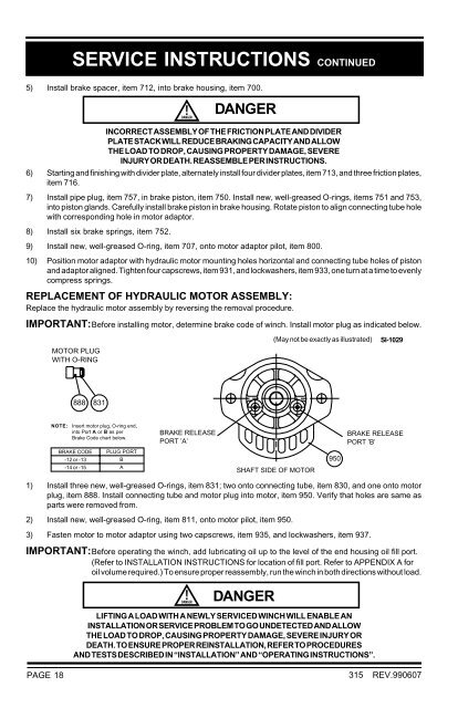
IMPORTANT:Before installing motor, determine brake code of winch. Install motor plug as indicated below.<br />
MOTOR PLUG<br />
WITH O-RING<br />
(May not be exactly as illustrated)<br />
SI-1029<br />
888 831<br />
NOTE:<br />
Insert motor plug, O-ring end,<br />
into Port A or B as per<br />
Brake Code chart below.<br />
BRAKE CODE<br />
-12 or -13<br />
-14 or -15<br />
PLUG PORT<br />
B<br />
A<br />
BRAKE RELEASE<br />
PORT ’A’<br />
SHAFT SIDE OF MOTOR<br />
950<br />
BRAKE RELEASE<br />
PORT ’B’<br />
1) Install three new, well-greased O-rings, item 831; two onto connecting tube, item 830, and one onto motor<br />
plug, item 888. Install connecting tube and motor plug into motor, item 950. Verify that holes are same as<br />
parts were removed from.<br />
2) Install new, well-greased O-ring, item 811, onto motor pilot, item 950.<br />
3) Fasten motor to motor adaptor using two capscrews, item 935, and lockwashers, item 937.<br />
IMPORTANT:Before operating the winch, add lubricating oil up to the level of the end housing oil fill port.<br />
(Refer to INSTALLATION INSTRUCTIONS for location of fill port. Refer to APPENDIX A for<br />
oil volume required.) To ensure proper reassembly, run the winch in both directions without load.<br />
DANGER<br />
LIFTING A LOAD WITH A NEWLY SERVICED WINCH WILL ENABLE AN<br />
INSTALLATION OR SERVICE PROBLEM TO GO UNDETECTED AND ALLOW<br />
THE LOAD TO DROP, CAUSING PROPERTY DAMAGE, SEVERE INJURY OR<br />
DEATH. TO ENSURE PROPER REINSTALLATION, REFER TO PROCEDURES<br />
AND TESTS DESCRIBED IN “INSTALLATION” AND “OPERATING INSTRUCTIONS”.<br />
PAGE 18<br />
315 REV.990607