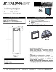
5300S 3 Hour Static Fire Damper Installation Instructions - Ventex
5300S 3 Hour Static Fire Damper Installation Instructions - Ventex
5300S 3 Hour Static Fire Damper Installation Instructions - Ventex

You also want an ePaper? Increase the reach of your titles
YUMPU automatically turns print PDFs into web optimized ePapers that Google loves.
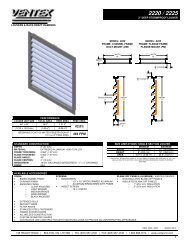
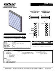
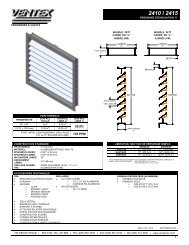
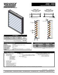
INSTALLATION INSTRUCTIONS FOR STATIC<br />
CURTAIN TYPE FIRE DAMPERS<br />
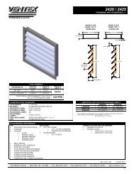
<strong>5300S</strong> SERIES • 3 HR. LABEL • VERTICAL MOUNT<br />
IMPORTANT GENERAL NOTES: When UL is referred to in this document, it represents UL/ULC. This installation<br />
instruction applies to static curtain type fire dampers mounted in the plane of an UL approved fire partition. These<br />
instructions meet the requirements of UL 555 and ULC S112. Vertical mount dampers must be installed with the blades<br />
running horizontally. The dampers are to be installed square and free from twisting or racking. The dampers shall not be<br />
compressed or stretched into the opening. Transportation and installation of the dampers shall be handled with the sleeve or<br />
frame. Do not lift the damper with the blades. Special care shall be given to the damper before installation and after to insure<br />
it is protected against dirt, weather, mortar and drywall dust, wall texture and paint. Any of these conditions could cause the<br />
damper not to operate correctly and void the warranty. Suitable access to inside duct is to be provided for inspection and<br />
replacement of parts such as heat response devices per NFPA 90A and local authority having jurisdiction. Sleeve-to-duct<br />
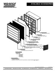
connections may be sealed using approved sealant (see Note 5). Alumavent Inc. model numbers which are UL approved to<br />
utilize this installation are 53AVS, 53BVS, 53CVS, 53CRVS and 53COVS.<br />
SAFETY WARNING:<br />
Improper installation, adjustment, alteration, service or maintenance can cause property damage, injury or death.<br />
Read the installation, operating, and maintenance instructions thoroughly before installing or servicing this<br />
equipment.<br />
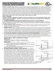
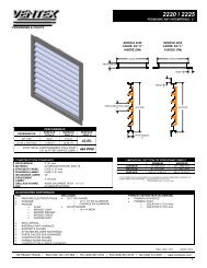
1. CLEARANCES REQUIRED BETWEEN FIRE DAMPER SLEEVES AND WALL OPENINGS:<br />
Due to the thermal expansion of fire dampers and sleeves during periods of extreme heat, it is essential that openings in walls be larger<br />
than the damper to allow for this expansion. Minimum clearances required between the outside of fire damper sleeve assemblies and wall<br />
openings are as follows:<br />
A. <strong>Damper</strong> assemblies using 2 Sided Angles method (see Note 4) shall be a minimum of 1/8”(3mm) per linear foot (305mm) of<br />
height and width of sleeved assembly with a minimum of 1/4” (6mm). The maximum opening size shall be 2” (51) larger in either dimension<br />
than the allowable minimum size.<br />
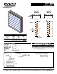
2. DAMPER SLEEVE: Sleeves shall be of the SAME GAUGE or heavier as the duct to which it is attached, if one of the breakaway<br />
connection is used as defined in the SMACNA <strong>Fire</strong>, Smoke and Radiation <strong>Damper</strong> Guide for HVAC Systems and in NFPA 90A.<br />
Gauges shall conform to SMACNA or ASHRAE duct standards. Sleeves shall not extend beyond the fire barrier more than 6”(152mm)<br />
unless a factory installed access door is supplied, then the sleeve may extend up to 16”(406mm). Sleeve shall terminate at both sides<br />
of wall within dimensions shown. If a rigid connection is used, then the sleeve shall be a minimum of 16 Ga. for dampers up to 36”<br />
914mm) wide by 24”(610mm) high and 14 Ga. for dampers exceeding 36” (914mm) wide by 24” (610mm) high.<br />
3. ATTACHING FIRE DAMPERS TO SLEEVES and MULTIPLE SECTION FIRE DAMPERS: <strong>Damper</strong> shall be secured on<br />
all four sides to the sleeve, and to each other when multiple sections are shipped unassembled, as follows: Use #10 sheet metal<br />
screws, ¼” (6mm) nuts and bolts, ¼” (6mm) tack welds or 3/16” (5mm) steel rivets, spaced a maximum of 6” (152 mm) on centers and<br />
a maximum of 2” (51mm) from the corners. A minimum of 4 attachments (2 on each side of the blade track) per side (16 per damper)<br />
are required. 3 section wide assemblies require additional damper-to-sleeve fasteners at bottom of sleeve, 2” (51) each side from the<br />
centerline of the middle section. Fasteners are not to be located inside the blade track.<br />
Maximum sizes for “Type A” dampers are as follows:<br />
Single Section<br />
53AVS <strong>Static</strong>, Vertical Mount only (3 hr. label): 36” x 48” (914 x 1219mm).<br />
Multiple Section<br />
53AVS <strong>Static</strong>, Vertical Mount only (3 hr. label): 108” x 96” (2743 x 2438mm).<br />
Note: Type B and C dampers have the same overall damper size but the connection ducts are smaller due to the B or C enclosures.<br />
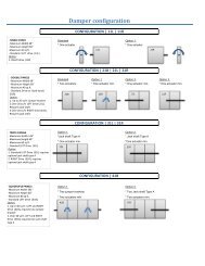
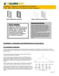
4. SECURING DAMPER IN OPENING (2 ANGLE METHOD): In this method 2 sets of angles are used to secure the damper in<br />
the opening, one on each side of the partition (See Figures 1 through 5). Two Angle Method is approved for 3 Hr. installations and<br />
any maximum size multi-section UL approved damper. Angles shall be a minimum of 1 1/2” x 1 1/2” (38mm x 38mm) x 16 Ga. The<br />
angles are to overlap the partition a minimum of 1”(25mm). These angles may be of a unit type construction and may or may not be<br />
fastened to each other at the corners. Angles are to be fastened to the sleeve on 6” centers with #10 (M5mm) sheet metal screws,<br />
3/16” (5mm) steel pop rivets,1/2” (13mm) tack welds, or 1/4” (6mm) diameter nut and bolts and not more than 2” (51mm) from each<br />
end with a minimum of two connections per side/leg. When the duct work terminates at the damper or installation prohibits angles from<br />
turning out/away from the wall, the retaining angle shall be reversed (leg turned into the opening) providing the size of the opening is<br />
increased by an amount equal to twice the combined thickness of the angle and the height of the screw or bolt head to maintain<br />
expansion clearances. See Note 1A for information on clearances. See Fig. 5 for detailed drawings of installations. Retaining angles<br />
should not be fastened to the wall material. The angles should only sandwich the partition and allow for damper / sleeve expansion<br />
during periods of intense heat.<br />
5/2012 FD3 IOM Page 1
Figure 1<br />
Figure 2<br />
Figure 3<br />
Figure 4<br />
Figure 5<br />
5. BREAKAWAY DUCT/SLEEVE CONNECTIONS:<br />
Rectangular ducts must use one or more of the following<br />
connects if the gauge is less than the requirement in Note 2 for<br />
rigid connections.<br />
Additionally, a maximum of two #10 sheet metal screws on<br />
each side and on the bottom, located in the center of the slip<br />
pocket and penetrating both sides of the slip pocket may be<br />
used.<br />
One of the connections shown in Figure 6 on the top and<br />
bottom joints with flat drive slip connections (shown below,<br />
Figure 7) on the side joints may be used for dampers up to 20”<br />
(508mm) in height.<br />
Figure 6<br />
Figure 7<br />
5/2012 FD3 IOM Page 2
Round or flat oval ducts connected to Type C, CR or CO damper collars may use no. 10 sheet metal screws as follows:<br />
• Duct diameters to 22" (558mm) and smaller may use 3 screws, equally spaced around the circumference.<br />
• Duct diameters larger than 22" (558mm) and up to 36" (914mm) dia. may use 5 screws, equally spaced around the<br />
circumference.<br />
• Duct diameters larger than 36” (914 mm) may use eight screws, equally spaced around the circumference.<br />
NOTE: All breakaway connections described may have duct sealant, PA2048T duct sealant adhesive manufactured by<br />
Precision, DP1010 water base duct sealant by Design Polymetrics, or Grey Pookie applied in accordance with SMACNA<br />
recommendations.<br />
Proprietary Flange System Breakaway Connections<br />
(Ductmate, Ward, Nexus)<br />
6 in. long 1/16 in. max.<br />
Flanged connection systems manufactured by Ductmate,<br />
Ward and Nexus are approved as breakaway connections<br />
when installed as illustrated.<br />
Figure 8<br />
TDC by Lockformer, TDF by Engle:<br />
TDC and TDF systems are approved as breakaway<br />
connections when installed as per manufacturer’s<br />
instructions using 6” (152mm) metal clips spaced as<br />
shown, gaskets and four 3/8” (9.5mm) bolts and<br />
nuts (optional). Refer also to the SMACNA HVAC<br />
Duct Construction Standards and SMACNA <strong>Fire</strong><br />
<strong>Damper</strong> <strong>Installation</strong> Guide.<br />
Figure 9<br />
<strong>Damper</strong> Maintenance<br />
<strong>Damper</strong>s shall be maintained, cycled and tested in intervals as stated in the latest editions of NFPA 80 and 90A unless local<br />
codes require more frequent inspections.<br />
<strong>Damper</strong>s do not usually require maintenance as long as they are kept dry and clean. If cleaning is required use mild<br />
detergents or solvents. Do not use oil-based lubricants or any other lubricants that attract and retain contaminants such as<br />
dust.<br />
Trouble Shooting Chart<br />
Symptom Possible Cause Corrective Action<br />
<strong>Damper</strong> does not fully open and or fully<br />
close<br />
Frame is out of square causing blades<br />
to bind on track or jamb.<br />
Adjust damper frame such that it is<br />
square and there is no twisting.<br />
Contaminants on damper<br />
Clean blades with a non oil based<br />
solvent.<br />
Screws in damper blade track.<br />
Find screws in the damper blade track<br />
and remove.<br />
Blades will not stay open Link melted by heat. Replace Link.<br />
195 HEALEY ROAD | BOLTON, ON. L7E 5B2 | TEL (905) 857-4700 | FAX (905) 857-4730 | 1-800-668-7214 | www.ventexinc.com<br />
5/2012 FD3 IOM Page 3