Worksheet 3: Quantitative Circuit Analysis - Modeling Physics
Worksheet 3: Quantitative Circuit Analysis - Modeling Physics
Worksheet 3: Quantitative Circuit Analysis - Modeling Physics

Create successful ePaper yourself
Turn your PDF publications into a flip-book with our unique Google optimized e-Paper software.
Electric <strong>Circuit</strong> Model <strong>Worksheet</strong> 3:<br />
<strong>Quantitative</strong> <strong>Circuit</strong> <strong>Analysis</strong><br />
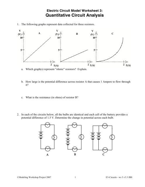
1. The following graphs represent data collected for three resistors.<br />
a. Which graph(s) represent "ohmic" resistors Explain.<br />
b. How large is the potential difference across resistor A that causes 1 Ampere to flow through<br />
it<br />
c. What is the resistance (in ohms) of resistor B<br />
2. In each of the circuits below, all the bulbs are identical and each cell of the battery provides a<br />
potential difference of 1.5 V. Determine the change in potential across each bulb.<br />
A B C<br />
©<strong>Modeling</strong> Workshop Project 2007 1 E3-<strong>Circuit</strong>s - ws 3 v3.3 JBS
3. In each of the diagrams below, draw rings showing the surface charge distribution at the<br />
terminals to each circuit device.<br />
a. Rank the flow rates through points A, B and C. Explain your ranking.<br />
b. Rank the potentials at A, B and C relative to the negative terminal of the battery. Explain<br />
your ranking.<br />
c. Rank the flow rates through points X, Y and Z. Explain your ranking.<br />
d. Rank the potentials at X, Y and Z relative to the negative terminal of the battery. Explain your<br />
ranking.<br />
©<strong>Modeling</strong> Workshop Project 2007 2 E3-<strong>Circuit</strong>s - ws 3 v3.3 JBS
4. The circuit on the right consists of bulbs of identical<br />
resistance and a 3V battery.<br />
a. Draw rings showing the surface charge<br />
distribution at the terminals to each circuit device.<br />
b. What is the change in potential across each bulb<br />
A<br />
B<br />
C<br />
c. How does the flow rate through A compare to that<br />
through B Explain.<br />
d. How many times brighter should A be compared to B Explain.<br />
5. For the series circuit at right draw rings showing<br />
the surface charge distribution at the terminals to<br />
each circuit device.<br />
a<br />
3V<br />
b<br />
a. What is the ∆V between:<br />
a and b<br />
12 !<br />
b and c<br />
c and d<br />
d<br />
6 !<br />
c<br />
d and a<br />
b. Calculate the current in this circuit.<br />
c. Determine the power dissipation by each resistor.<br />
©<strong>Modeling</strong> Workshop Project 2007 3 E3-<strong>Circuit</strong>s - ws 3 v3.3 JBS
6. For the parallel circuit at right draw rings<br />
showing the surface charge distribution at<br />
the terminals to each circuit device.<br />
3V<br />
a<br />
c<br />
a. Determine the equivalent resistance<br />
of the circuit.<br />
12 ! 6 !<br />
b<br />
d<br />
b. What is the ∆V between:<br />
a and b<br />
c and d<br />
c. What is the current in each of the branches<br />
d. What is the current in the wire leading from the battery to point a<br />
e. Determine the power dissipation by each resistor.<br />
©<strong>Modeling</strong> Workshop Project 2007 4 E3-<strong>Circuit</strong>s - ws 3 v3.3 JBS