Capilube Bearings with solid lubricant oil
Capilube Bearings with solid lubricant oil
Capilube Bearings with solid lubricant oil

Create successful ePaper yourself
Turn your PDF publications into a flip-book with our unique Google optimized e-Paper software.
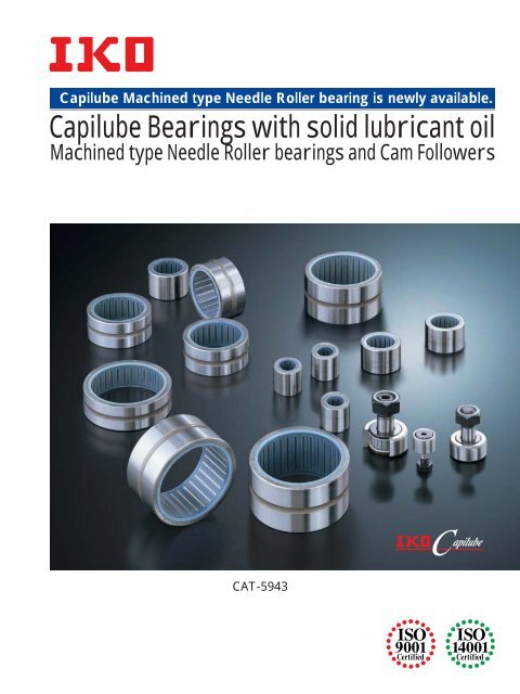
<strong>Capilube</strong> Machined type Needle Roller bearing is newly available.<br />
<strong>Capilube</strong> <strong>Bearings</strong> <strong>with</strong> <strong>solid</strong> <strong>lubricant</strong> <strong>oil</strong><br />
Machined type Needle Roller bearings and Cam Followers<br />
CAT-5943
<strong>Capilube</strong> bearings are bearings that are<br />
pre-packed <strong>with</strong> thermosetting <strong>solid</strong> <strong>lubricant</strong><br />
(<strong>Capilube</strong>) in the bearing space. <strong>Capilube</strong> is a<br />
<strong>lubricant</strong> made by thermosetting a large<br />
amount of <strong>oil</strong> and fine particles of ultra high<br />
molecular weight polyolefine resin. As the<br />
bearing rotates, the lubricating <strong>oil</strong> oozes out<br />
onto the raceway in proper quantity, keeping<br />
the lubrication performance for a long period<br />
of time.<br />
Feature of<br />
<strong>Capilube</strong> bearings<br />
Maintenance work can be reduced greatly<br />
Work for lubrication control can be reduced<br />
by a good lubrication performance kept by<br />
pre-packed <strong>solid</strong> type <strong>lubricant</strong>.<br />
Best suit for <strong>oil</strong> free environment<br />
applications<br />
No <strong>oil</strong> scattering makes any pollution in the<br />
ambient environment.<br />
Best remedy for grease loss<br />
Applications<br />
Most suitable for applications of printing machines,<br />
food-manufacturing machines, liquid<br />
crystal/semiconductor manufacturing equipment,<br />
various types of washing line, various<br />
types of transport lines, etc.<br />
With retainer<br />
Crowned outer ring<br />
is effective in moderating<br />
the edge load due to<br />
mounting errors.<br />
Best solution for grease loss at hard-to<br />
grease positions by the restriction of machine/equipment<br />
structure.<br />
<strong>Capilube</strong> Machined type<br />
Needle Roller bearings<br />
Outer ring<br />
Many needle rollers are arranged at a<br />
small spacing pitch, and can make<br />
bearing sectional height very low.<br />
It is the most suitable to oscillating<br />
motions.<br />
Needle roller<br />
Cage<br />
With hexagon<br />
socket hole<br />
for easy mounting<br />
Thrust disk<br />
is effective in supporting<br />
unexpected thrust load due<br />
to mounting errors.<br />
With seals<br />
<strong>Capilube</strong> Cam Followers<br />
With a pre-packed <strong>solid</strong> type<br />
<strong>lubricant</strong>, the lubrication performance<br />
can be kept for a<br />
long time.<br />
Cam Follower is the best bearing for cam<br />
mechanism and linear motion and has high<br />
rigidity and high accuracy.<br />
Capiluibe<br />
Needle roller<br />
1 2
Maintenance Free bearing series<br />
[ <strong>Capilube</strong> <strong>Bearings</strong> <strong>with</strong> <strong>solid</strong> <strong>lubricant</strong> <strong>oil</strong> ]<br />
Machined type Needle Roller bearings<br />
With a low sectional height, it can have large load ratings.<br />
Machined outer ring has superior rigidity and can be fitted into light alloy housing.<br />
TAF 12 19 12 P6 /SG<br />
∆<br />
F Fws min<br />
w<br />
Deviation of the smallest<br />
Nominal roller set bore diameter<br />
mm<br />
single roller set bore diameter<br />
m<br />
D<br />
∆ Dmp ∆ Cs<br />
Over<br />
Incl.<br />
High<br />
Low<br />
10<br />
18<br />
27<br />
16<br />
18<br />
30<br />
33<br />
20<br />
30<br />
45<br />
41<br />
25<br />
Note ( 1 ) : This is the diameter of the cylinder used instead of the inner ring,<br />
where the radial clearance becomes zero at least in one radial direction.<br />
Design of shaft and housing<br />
<strong>Capilube</strong> Machined type Needle Roller bearings does not<br />
have inner ring so that the shaft can be used directly as the raceway<br />
surfaces. Shaft and housing according to specification in<br />
Table 3 are recommended.<br />
Oscillating endurance test<br />
Table 3 Specification of shaft and housing<br />
Test conditions<br />
Item Shaft Housing<br />
Test bearing:<br />
0.31T6 ( 1 )<br />
0.31T7 ( 1 )<br />
<br />
<strong>Capilube</strong> Machined type<br />
Roundness<br />
or<br />
or<br />
Needle Roller bearing : TAF253316/SG<br />
0.31T5 ( 1 )<br />
<br />
0.31T6 ( 1 )<br />
Oscillating angle : 2θ=151°<br />
0.31T6 ( 1 )<br />
<br />
0.51T7 ( 2 )<br />
<br />
Oscillating speed : 217cpm<br />
Cylindricity<br />
or<br />
or<br />
Load amount<br />
: 1960N<br />
0.31T5 ( 1 )<br />
0.51T6 ( 2 )<br />
Ambient temperature : Room temperature<br />
Surface roughness 0.2mR ( 3 )<br />
100<br />
100<br />
a 1.6mR a <br />
90<br />
90<br />
Hardness 5864HRC ( 4 )<br />
<br />
80<br />
Residual <strong>oil</strong> content ratio<br />
80<br />
70<br />
70<br />
Note ( 30% or less of the dimensional tolerance for the shafts or housing<br />
in the bearing<br />
) :<br />
bores is recommended.<br />
60<br />
60<br />
(<br />
50<br />
50<br />
) : 50% or less of the dimensional tolerance for shafts or housing bores is<br />
recommended.<br />
40<br />
40<br />
( 3 ) : When required accuracy is not critical, a surface roughness <strong>with</strong>in 0.8<br />
30<br />
30<br />
mR a (3.2m R y ) is allowable.<br />
20<br />
Bearing temperature<br />
20<br />
( 4 ) : An appropriate depth of the hardened layer is required.<br />
10<br />
10<br />
0 0<br />
0 1 000 2 000 3 000<br />
Number of oscillation x 10 Allowable rotational speed<br />
times<br />
The allowable rotational speeds of <strong>Capilube</strong> Machined<br />
Accuracy<br />
type Needle Roller bearings are affected by mounting and operating<br />
conditions. Recommended d m n value (1 ) is less than 20,000<br />
The accuracy of <strong>Capilube</strong> Machined type Needle Roller<br />
under pure radial load condition. Under actual usage, d m n value is<br />
bearings conforms to JIS B 1514:2000 (Tolerances of Rolling <strong>Bearings</strong>),<br />
recommended to be less than 2,000 due to unexpected axial load.<br />
and the dimensional accuracy and rotational accuracy are<br />
Note (<br />
specified. Representative tolerances of outer ring are shown in<br />
) :<br />
Value d mn = (Bearing bore dia. [mm] +Bearing outside dia.[mm])/2 x Number of revolution [rpm]<br />
Table 1 and the tolerances for the smallest single roller set bore<br />
diameter is shown in Table 2.<br />
Table 1 Tolerance for outer ring<br />
unit:m<br />
Nominal<br />
Single plane mean outside Deviation of a single outer<br />
bearing<br />
diameter deviation<br />
ring width<br />
outside<br />
diameter<br />
Class Class Class Class Class Class Class Class<br />
mm 0 6 5 4 0 6 5 4<br />
<strong>Capilube</strong> Machined type Needle Roller bearing is a needle roller bearing that is prepacked<br />
<strong>with</strong> thermosetting <strong>solid</strong> <strong>lubricant</strong> (<strong>Capilube</strong>) in the bearing space. As the bearing rotates,<br />
the lubricating <strong>oil</strong> oozes out onto the raceway in proper quantity, keeping the lubrication<br />
performance for a long period of time.<br />
Residual <strong>oil</strong> content ratio<br />
in the bearing %<br />
100<br />
90<br />
80<br />
70<br />
60<br />
50<br />
40<br />
30<br />
20<br />
10<br />
0<br />
Rotational endurance test<br />
Test conditions<br />
Test bearing:<br />
<strong>Capilube</strong> Machined type<br />
Needle Roller bearing : TAF455520/SG<br />
Rotational speed : 400rpm<br />
Load amount<br />
: 3000N<br />
Ambient temperature : Room temperature<br />
100<br />
90<br />
80<br />
70<br />
60<br />
50<br />
40<br />
30<br />
20<br />
10<br />
0<br />
0 1 000 2 000 3 000 4 000 5 000<br />
Operation time min<br />
Identification number<br />
The identification number example of<br />
type Needle Roller bearing is shown.<br />
Identification number<br />
Type of bearing<br />
/SG: <strong>Capilube</strong> specification<br />
Bearing bore diameter<br />
Bearing outside diameter<br />
Outer ring width<br />
Accuracy class<br />
Basic dynamic load rating<br />
The basic dynamic load rating is defined as the constant radial<br />
load acting along the bearing central axis that allows a basic rating<br />
life of 1,000,000 revolutions.<br />
Basic static load rating<br />
Residual <strong>oil</strong> content ratio<br />
in the bearing<br />
Bearing temperature<br />
Bearing temperature °C<br />
<strong>Capilube</strong> Machined<br />
Residual <strong>oil</strong> content ratio<br />
in the bearing %<br />
Over<br />
Incl.<br />
High<br />
Low<br />
High<br />
Low<br />
High<br />
Low<br />
<br />
<br />
—9<br />
—9<br />
<br />
<br />
—8<br />
—8<br />
<br />
<br />
—11 —9 <br />
—13 —11 <br />
—6<br />
—6<br />
—7<br />
—9<br />
High<br />
Low<br />
—5<br />
—5<br />
—6<br />
—7<br />
High<br />
Low<br />
High<br />
Low<br />
Bearing temperature °C<br />
High<br />
Low<br />
High<br />
Low<br />
—120 —120 <br />
—120 —120 <br />
—40 <br />
—80 <br />
—40<br />
—80<br />
—120 —120 —120 —120<br />
—120 —120 —120 —120<br />
Table 2<br />
Tolerances for the smallest single roller<br />
set bore diameter F ws min<br />
(1)<br />
Fit<br />
The recommended fits for <strong>Capilube</strong> Machined type Needle<br />
Roller bearings are shown in Table 4 to 5.<br />
Table 4 Fit between <strong>Capilube</strong> Machined type<br />
Needle Roller bearings and housings<br />
Tolerance class<br />
Load condition<br />
of housing<br />
Rotating load<br />
on outer ring<br />
Directionally<br />
indeterminate<br />
load<br />
Stationary load<br />
on outer ring<br />
N7 ( 1 )<br />
M7<br />
K7<br />
J7<br />
H7<br />
G7<br />
Note ( 1 ) : Care should be taken so that the radial internal clearance is not too<br />
small.<br />
Remark 1: This table applies to steel or cast iron housings. For lighter metal, a<br />
tighter fit should be selected. For split housings, do not use a fit tighter<br />
than J7.<br />
2: Light load and normal load represent P 0.06C and 0.06C
<strong>Capilube</strong> Machined type Needle Roller bearings<br />
C<br />
C<br />
r<br />
r<br />
D<br />
Fw<br />
D<br />
Fw<br />
Da<br />
r<br />
r<br />
F w 26<br />
(Without <strong>oil</strong> hole and <strong>oil</strong> groove)<br />
F w 26<br />
(With <strong>oil</strong> hole and <strong>oil</strong> groove)<br />
<br />
Shaft dia.<br />
<br />
mm<br />
Identification number<br />
Mass <br />
(Reference)<br />
<br />
g<br />
Boundary dimensions<br />
mm<br />
F w D C r s min (1 )<br />
Standard<br />
mounting dimension<br />
D a <br />
Max.<br />
mm<br />
Basic dynamic<br />
load rating<br />
C<br />
N<br />
Basic static<br />
load rating<br />
C 0 <br />
N<br />
Identification number<br />
12<br />
15<br />
18<br />
20<br />
22<br />
25<br />
30<br />
45<br />
TAF 121912/SG 12.5 12 19 12 0.3 17 6 610 7 260 TAF 121912/SG<br />
TAF 121916/SG 16.8 12 19 16 0.3 17 9 250 11 200 TAF 121916/SG<br />
TAF 152316/SG 23.5 15 23 16 0.3 21 12 300 14 900 TAF 152316/SG<br />
TAF 152320/SG 29 15 23 20 0.3 21 15 600 20 200 TAF 152320/SG<br />
TAF 182616/SG 26.5 18 26 16 0.3 24 13 400 17 500 TAF 182616/SG<br />
TAF 182620/SG 33 18 26 20 0.3 24 17 000 23 600 TAF 182620/SG<br />
TAF 202816/SG 28.5 20 28 16 0.3 26 13 900 18 800 TAF 202816/SG<br />
TAF 202820/SG 37 20 28 20 0.3 26 17 600 25 400 TAF 202820/SG<br />
TAF 223016/SG 31 22 30 16 0.3 28 14 900 21 200 TAF 223016/SG<br />
TAF 223020/SG 39 22 30 20 0.3 28 18 900 28 700 TAF 223020/SG<br />
TAF 253316/SG 35 25 33 16 0.3 31 15 800 23 700 TAF 253316/SG<br />
TAF 253320/SG 43.5 25 33 20 0.3 31 20 000 32 100 TAF 253320/SG<br />
TAF 304020/SG 67 30 40 20 0.3 38 25 100 40 100 TAF 304020/SG<br />
TAF 304030/SG 101 30 40 30 0.3 38 36 000 63 900 TAF 304030/SG<br />
TAF 455520/SG 95.5 45 55 20 0.3 53 31 000 60 200 TAF 455520/SG<br />
TAF 455530/SG 144 45 55 30 0.3 53 44 600 95 800 TAF 455530/SG<br />
Note ( 1 ) : Minimum allowable value of chamfer dimension r.<br />
Remark : Bearing <strong>with</strong> a roller set bore diameter F w of 26mm or less have no <strong>oil</strong> hole and <strong>oil</strong> groove. In others, the outer ring<br />
has an <strong>oil</strong> hole and an <strong>oil</strong> groove.<br />
Example of identification number<br />
1N0.102kgf<br />
Model code<br />
TAF<br />
Bearing bore diameter<br />
Bearing outside diameter<br />
Outer ring width<br />
Model<br />
code<br />
Dimension<br />
Accuracy<br />
class<br />
Model<br />
code<br />
TAF 12 19 12 P6 /SG<br />
No symbol<br />
P6<br />
P5<br />
P4<br />
Model code<br />
SG<br />
Accuracy class<br />
JIS Class 0<br />
JIS Class 6<br />
JIS Class 5<br />
JIS Class 4<br />
5 6
Identification number<br />
<strong>Capilube</strong> Cam Fol-<br />
An example of identification number of<br />
lower is shown.<br />
Identification number<br />
Maintenance free Needle Roller bearing series<br />
[ Pre-packed <strong>with</strong> <strong>solid</strong> type <strong>lubricant</strong> ]<br />
<strong>Capilube</strong> Cam Followers<br />
Cam Follower is bearing <strong>with</strong> a stud incorporating needle rollers in a thick walled outer ring. It<br />
has high rigidity and high accuracy and is suitable to cam and linear motion mechanisms.<br />
<strong>Capilube</strong> Cam Follower is a Cam Follower that is pre-packed <strong>with</strong> thermosetting <strong>solid</strong><br />
<strong>lubricant</strong> (<strong>Capilube</strong>) in the bearing space.<br />
The lubrication effect can be maintained in long time operation.<br />
It contributes to “Maintenance free”.<br />
Rotational endurance test<br />
Test condition<br />
Test product<br />
<strong>Capilube</strong> Cal Follower: CF10/SG<br />
Standard Cam Follower: CF10<br />
Rotational speed : 1,000rpm<br />
Ambient temperature : Room temperature<br />
Model code<br />
Size<br />
With thrust disk<br />
With hexagon hole<br />
Sealed type<br />
Crowned outer ring<br />
Basic dynamic load rating<br />
Residual <strong>oil</strong> content ratio in the bearing %<br />
100<br />
75<br />
50<br />
25<br />
CF 8 W B UU R /SG<br />
The basic dynamic load rating is defined as the constant radial<br />
load acting along the bearing central axis that allows a basic rating<br />
life of 1,000,000 revolutions.<br />
0 0 1 000 2 000 4 000 5 000<br />
Operation time min.<br />
Basic static load rating<br />
The basic static load rating is the static load that gives the contact<br />
stress reaches 4,000Mpa at the center of the contact area of the<br />
rolling elements and the raceway receiving the maximum load.<br />
Maximum Allowable Load<br />
The applicable load on <strong>Capilube</strong> Cam Follower is, in some<br />
cases, limited by the bearing strength, shear strength of stud, and<br />
strength of outer ring instead of the load rating of needle roller<br />
bearing, because the <strong>Capilube</strong> Cam Follower is mounted in<br />
a cantilever position. Maximum allowable loads limited by the<br />
bending strength and shear strength.<br />
Track capacity<br />
The capacity is defined as the load which can be continuously applied<br />
on a <strong>Capilube</strong> Cam Follower placed on a steel track<br />
surface <strong>with</strong>out causing deformation and indentation (dent) on the<br />
track surface.<br />
Accuracy<br />
The accuracy of <strong>Capilube</strong> Cam Follower is shown in Table 6.<br />
And the radial run-out of the outer ring is controlled 15m in maximum.<br />
Table 6<br />
Tolerances<br />
Allowable rotational speed<br />
Unit: m<br />
Outside diameter<br />
of outer ring Stud diameter<br />
Width<br />
of outer ring<br />
D d 1 C<br />
3 000 when heavy shock loads are applied.<br />
0<br />
0<br />
Tolerances<br />
h7<br />
-50<br />
-120<br />
Clearance<br />
The radial internal clearances of <strong>Capilube</strong> Cam Follower<br />
are shown in Table 7.<br />
Table 7 Radial internal clearance<br />
unit: m<br />
Radial internal clearance<br />
Identification number<br />
Min.<br />
Max.<br />
CF 6 WBUUR/SG<br />
5<br />
20<br />
<strong>Capilube</strong> Cam Follower<br />
CF 8 WBUUR/SG<br />
CF 10 WBUUR/SG<br />
CF 10-1 WBUUR/SG<br />
5<br />
25<br />
CF 12 WBUUR/SG<br />
CF 12-1 WBUUR/SG<br />
Remark: Values are applicable before the <strong>solid</strong> type <strong>lubricant</strong> is packed.<br />
Fit<br />
Standard Cam Follower<br />
Mounting hole tolerance for stud is recommended to be H7 for<br />
<strong>Capilube</strong> Cam Followers. In case it is supported in a cantilever<br />
position, the mounting hole diameter should be prepared<br />
<strong>with</strong>out play between the stud and the mounting hole especially<br />
The allowable rotational speeds of <strong>Capilube</strong> Cam Follower<br />
are affected by mounting and operating conditions.<br />
Recommended d 1 n value (1 ) is less than 10,000 under pure radial<br />
load condition. Under actual usage, d 1 n value is recommended to<br />
be less than 1,000 due to unexpected axial load.<br />
Note ( 1 ) :<br />
Value d 1n = d 1 (Stud diameter [mm]) x n (Number of revolution [rpm])<br />
Mounting<br />
1. Make the center axis if the mounting hole perpendicular to the<br />
moving direction of the <strong>Capilube</strong> Cam Follower and<br />
match the side shoulder accurately <strong>with</strong> the seating surface indicated<br />
by dimension f in the table of dimensions. Then, fix the<br />
Cam Follower <strong>with</strong> the nut. Do not hit the flange head of the<br />
<strong>Capilube</strong> Cam Follower directly <strong>with</strong> a hammer, etc. This<br />
may lead to a bearing failure such as irregular rotation or cracking.<br />
2. The mark on the flange head of the stud indicates the <strong>oil</strong><br />
hole position on the raceway. Avoid locating the <strong>oil</strong> hole <strong>with</strong>in<br />
the loading zone which may lead to a short bearing life. (See<br />
Fig.1)<br />
Caution for use<br />
Load<br />
Oil hole<br />
Fig.1 Oil hole position and loading direction<br />
3. When tightening the nut, the tightening torque should not exceed<br />
the value shown in the dimension table. If the tightening<br />
torque is too large, it is possible that the threaded portion of the<br />
stud will be broken. When there is a possibility of loosening, a<br />
special nut such as lock nut, spring washer, or self-locking nut<br />
should be used.<br />
1. Never wash bearing <strong>with</strong> organic solvent and/or white kerosene,<br />
which have the ability to remove fat.<br />
2. To ensure normal rotation of the bearing, apply a load of 1% or<br />
more of the dynamic load rating at use.<br />
3. The operating temperature range is -15 to +80°C. For continuous<br />
operation, the recommended operating temperature is<br />
+60°C or less.<br />
4. When the <strong>lubricant</strong> status is not enough between the outer ring<br />
and the mating track surface, seizure or wear may be occurred<br />
depending on the operating conditions. In particular, care must<br />
be taken for lubricating condition and contacting surface roughness<br />
in case high-speed cam mechanisms.<br />
7<br />
8
G<br />
f<br />
<strong>Capilube</strong> Cam Followers<br />
C<br />
B 3<br />
g 2<br />
D<br />
H<br />
d1<br />
G 1<br />
R=500<br />
C 1<br />
B 2<br />
B<br />
B 1<br />
<br />
Stud dia.<br />
<br />
mm<br />
Identification number<br />
Mass <br />
(Reference) <br />
g<br />
Boundary dimension<br />
mm<br />
D C d 1 G B B 1<br />
max. max.<br />
G 1<br />
B 2 B 3 C 1 g 2 H<br />
Mounting <br />
dimension <br />
f<br />
Min.<br />
mm<br />
Maximum <br />
tightening <br />
torque <br />
Nm<br />
Basic dynamic <br />
load rating<br />
C<br />
N<br />
Basic static<br />
load rating<br />
C 0 <br />
N<br />
Maximum <br />
allowable <br />
load <br />
N<br />
Track <br />
capacity <br />
(1 )<br />
<br />
N<br />
Identification number<br />
6<br />
CF 6 WBUUR/SG<br />
18.5<br />
16<br />
11<br />
6<br />
M 6 1<br />
8<br />
12.2<br />
28.2<br />
16<br />
–<br />
0.6<br />
–<br />
3<br />
11<br />
2.7<br />
3 660<br />
3 650<br />
1 950<br />
1 040<br />
CF 6 WBUUR/SG<br />
8<br />
CF 8 WBUUR/SG<br />
28.5<br />
19<br />
11<br />
8<br />
M 8 1.25<br />
10<br />
12.2<br />
32.2<br />
20<br />
–<br />
0.6<br />
–<br />
4<br />
13<br />
6.5<br />
4 250<br />
4 740<br />
4 620<br />
1 330<br />
CF 8 WBUUR/SG<br />
CF 10<br />
WBUUR/SG<br />
45<br />
22<br />
12<br />
10<br />
M10 1.25<br />
12<br />
13.2<br />
36.2<br />
23<br />
–<br />
0.6<br />
–<br />
4<br />
16<br />
13.8<br />
5 430<br />
6 890<br />
6 890<br />
1 610<br />
CF 10<br />
WBUUR/SG<br />
10<br />
CF 10-1 WBUUR/SG<br />
60<br />
26<br />
12<br />
10<br />
M10 1.25<br />
12<br />
13.2<br />
36.2<br />
23<br />
–<br />
0.6<br />
–<br />
4<br />
16<br />
13.8<br />
5 430<br />
6 890<br />
6 890<br />
2 030<br />
CF 10-1 WBUUR/SG<br />
CF 12<br />
WBUUR/SG<br />
95<br />
30<br />
14<br />
12<br />
M12 1.5<br />
13<br />
15.2<br />
40.2<br />
25<br />
6<br />
0.6<br />
3<br />
6<br />
21<br />
21.9<br />
7 910<br />
9 790<br />
9 790<br />
2 470<br />
CF 12<br />
WBUUR/SG<br />
12<br />
CF 12-1 WBUUR/SG<br />
105<br />
32<br />
14<br />
12<br />
M12 1.5<br />
13<br />
15.2<br />
40.2<br />
25<br />
6<br />
0.6<br />
3<br />
6<br />
21<br />
21.9<br />
7 910<br />
9 790<br />
9 790<br />
2 710<br />
CF 12-1 WBUUR/SG<br />
Note ( 1 ) : Values in the table are applicable when the hardness of the mating track surface is 40HRC. When the hardness of the mating<br />
track surface differs from 40HRC, the track capacity is obtained by multiplying track capacity factor shown in Table 8.<br />
Remark : Models <strong>with</strong> a stud diameter d 1 of 10mm or less has no <strong>oil</strong> hole. The others are provided <strong>with</strong> one <strong>oil</strong> hole each on the outside surface<br />
and end surface of the stud.<br />
1N0.102kgf<br />
Table 8 Track capacity factor<br />
Hardness<br />
HRC<br />
Tensile strength<br />
N/mm 2<br />
Track capacity<br />
factor<br />
20<br />
760<br />
0.22<br />
25<br />
840<br />
0.31<br />
30<br />
950<br />
0.45<br />
35<br />
1 080<br />
0.65<br />
38<br />
40<br />
1 180<br />
1 250<br />
0.85<br />
1.00<br />
Example of identification number<br />
42<br />
44<br />
46<br />
48<br />
50<br />
52<br />
54<br />
56<br />
58<br />
1 340<br />
1 435<br />
1 530<br />
1 635<br />
1 760<br />
1 880<br />
2 015<br />
2 150<br />
2 290<br />
1.23<br />
1.52<br />
1.85<br />
2.27<br />
2.80<br />
3.46<br />
4.21<br />
5.13<br />
6.26<br />
Model code<br />
CF<br />
Dimension<br />
Supplemental code –1:<br />
With thrust washer<br />
Supplemental code –2 :<br />
With hexagon hole<br />
Model<br />
code<br />
Dimension<br />
Supplemental code<br />
Model<br />
code<br />
CF 8 W B UU R /SG<br />
Model code<br />
SG<br />
Supplemental code –4:<br />
Crowned outer ring<br />
Supplemental code –3:<br />
Sealed type<br />
9 10
<strong>Capilube</strong> <strong>Bearings</strong><br />
Printed in Japan<br />
2004.09 (SIG)