ZERON 100 Welding Guide [Corrosion Resistant ... - Rolled Alloys
ZERON 100 Welding Guide [Corrosion Resistant ... - Rolled Alloys
ZERON 100 Welding Guide [Corrosion Resistant ... - Rolled Alloys

You also want an ePaper? Increase the reach of your titles
YUMPU automatically turns print PDFs into web optimized ePapers that Google loves.
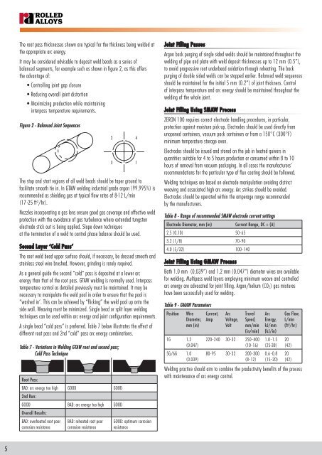
The root pass thicknesses shown are typical for the thickness being welded at<br />
the appropriate arc energy.<br />
It may be considered advisable to deposit weld beads as a series of<br />
balanced segments, for example such as shown in figure 2, as this offers<br />
the advantage of:<br />
• Controlling joint gap closure<br />
• Reducing overall joint distortion<br />
• Maximizing production while maintaining<br />
interpass temperature requirements.<br />
Figure 2 - Balanced Joint Sequences<br />
The stop and start regions of all weld beads should be taper ground to<br />
facilitate smooth tie in. In GTAW welding industrial grade argon (99.995%) is<br />
recommended as shielding gas at typical flow rates of 8-12 L/min<br />
(17 -25 ft 3 /hr).<br />
Nozzles incorporating a gas lens ensure good gas coverage and effective weld<br />
protection with the avoidance of gas turbulence where extended tungsten<br />
electrode stick out is being applied. Slope down techniques<br />
at the termination of a weld to control phase balance should be used.<br />
Second Layer ‘Cold Pass’<br />
The root weld bead upper surface should, if necessary, be dressed smooth and<br />
stainless steel wire brushed. However, grinding is rarely required.<br />
As a general guide the second “cold” pass is deposited at a lower arc<br />
energy than that of the root pass. GTAW welding is normally used. Interpass<br />
temperature control as detailed previously must be maintained. It may be<br />
necessary to manipulate the weld pool in order to ensure that the pool is<br />
“washed in’. This can be achieved by “flicking” the weld pool up onto the<br />
side wall. Weaving must be minimized. Single bead or split layer welding<br />
techniques can be used within arc energy and joint configuration requirements.<br />
A single bead “cold pass” is preferred. Table 7 below illustrates the effect of<br />
different root pass and 2nd “cold” pass arc energy combinations.<br />
Table 7 - Variations in <strong>Welding</strong> GTAW root and second pass;<br />
Cold Pass Technique<br />
Root Pass:<br />
BAD: arc energy too high GOOD GOOD<br />
2nd Run:<br />
GOOD BAD: arc energy too high GOOD<br />
Overall Results:<br />
BAD: overheated root poor<br />
corrosion resistance<br />
BAD: reheated root poor<br />
corrosion resistance<br />
2<br />
3<br />
GOOD: optimum corrosion<br />
resistance<br />
4<br />
1<br />
Joint Filling Passes<br />
Argon back purging of single sided welds should be maintained throughout the<br />
welding of pipe and plate with weld deposit thicknesses up to 12 mm (0.5”),<br />
to avoid progressive root underbead oxidation through reheating. The back<br />
purging of double sided welds can be stopped earlier. Balanced weld sequences<br />
should be maintained for the initial 5 mm (0.2”) of joint thickness. Control<br />
of interpass temperature and arc energy should be maintained throughout the<br />
welding of the whole joint.<br />
Joint Filling Using SMAW Process<br />
<strong>ZERON</strong> <strong>100</strong> requires correct electrode handling procedures, in particular,<br />
protection against moisture pick-up. Electrodes should be used directly from<br />
unopened containers, vacuum pack containers or from a 150°C (300°F)<br />
minimum temperature storage oven.<br />
Electrodes should be issued and stored on the job in heated quivers in<br />
quantities suitable for 4 to 5 hours production or consumed within 8 to 10<br />
hours of removal from vacuum packaging. In all cases the manufacturers’<br />
recommendations for the particular type of flux coating should be followed.<br />
<strong>Welding</strong> techniques are based on electrode manipulation avoiding distinct<br />
weaving and associated high arc energy. Arc strikes should be avoided.<br />
Electrodes should be operated within the amperage range recommended<br />
by the manufacturers.<br />
Table 8 - Range of recommended SMAW electrode current settings<br />
Electrode Diameter, mm (in)<br />
Current Range, DC + (A)<br />
2.5 (0.10) 50-65<br />
3.2 (1/8) 70-90<br />
4.0 (5/32) <strong>100</strong>-140<br />
Joint Filling Using GMAW Process<br />
Both 1.0 mm (0.039”) and 1.2 mm (0.047”) diameter wires are available<br />
for welding. Multipass weld layers employing minimum weave and controlled<br />
arc energy are advocated for joint filling. Argon/helium (CO 2) gas mixtures<br />
have been successfully used for welding.<br />
Table 9 - GMAW Parameters<br />
Position<br />
Wire<br />
Diameter,<br />
mm (in)<br />
1G 1.2<br />
(0.047)<br />
5G/6G 1.0<br />
(0.039)<br />
Current,<br />
Amp<br />
Arc<br />
Voltage,<br />
Volt<br />
Travel<br />
Speed,<br />
mm/min<br />
(in/min)<br />
220-240 30-32 250- 400<br />
(10-16)<br />
80-95 30-32 200-300<br />
(8-12)<br />
Arc<br />
Energy,<br />
kJ/mm<br />
(kJ/in)<br />
1.0 - 1.5<br />
(25-38)<br />
0.6 - 0.8<br />
(15-20)<br />
Gas Flow,<br />
L/min<br />
(ft 3 /hr)<br />
20<br />
(42)<br />
20<br />
(42)<br />
<strong>Welding</strong> practice should aim to combine the productivity benefits of the process<br />
with maintenance of arc energy control.<br />
5