guidelines for designers / builders and heat installers - Bord Gais ...
guidelines for designers / builders and heat installers - Bord Gais ...
guidelines for designers / builders and heat installers - Bord Gais ...

You also want an ePaper? Increase the reach of your titles
YUMPU automatically turns print PDFs into web optimized ePapers that Google loves.
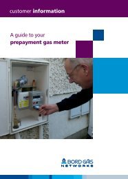
gas pipework installations <strong>for</strong> residential properties<br />
<strong>guidelines</strong> <strong>for</strong> <strong>designers</strong> /<br />
<strong>builders</strong> <strong>and</strong> <strong>heat</strong><br />
<strong>installers</strong><br />
2
Contents <strong>and</strong> general<br />
in<strong>for</strong>mation<br />
It is a legal requirement under The Energy<br />
(miscellaneous provisions) Act 2006 that all<br />
“domestic gas works” must be under taken <strong>and</strong><br />
certified by a registered gas installer (RGI) who is<br />
registered with the RGII (Register Gas Installers<br />
of Irel<strong>and</strong>). This guide prepared by <strong>Bord</strong> Gáis is<br />
intended to assist <strong>installers</strong> but is not to be used<br />
as an alternative to the most up to date edition of<br />
I.S.813.<br />
Contents Page 2<br />
The Meter box Page 3<br />
Safety <strong>for</strong> the home<br />
owner<br />
Safety, certificate &<br />
getting connected<br />
Important notice to all <strong>installers</strong> Page 35<br />
Steps to admitting gas to<br />
new home Page 36<br />
Commissioning the installation Page 37<br />
Declaration of Con<strong>for</strong>mance Page 39<br />
The Irish St<strong>and</strong>ards &<br />
Contact Details Page 40<br />
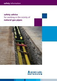
Natural gas pipework<br />
Gas installation pipework Page 4<br />
Pipe materials & sizing Page 5<br />
Jointing of pipes Page 8<br />
Pipework protection Page 9<br />
Pipework from the Meter to<br />
the building<br />
Extended pipework runs Page 11<br />
Installation pipework beneath<br />
footpaths Page 12<br />
Installation pipework beneath<br />
roads & l<strong>and</strong>scaped areas Page 12<br />
Polyethylene pipework Page 13<br />
Pipework within the building<br />
Pipes laid in floors Page 15<br />
Vertical pipe runs Page 18<br />
Dry lined walls Page 19<br />
Timber framed walls Page 20<br />
Internal pipework ducts Page 23<br />
Supports & fixings Page 24<br />
Natural gas <strong>and</strong> electrical<br />
considerations<br />
Gas meters & electrical elements Page 25<br />
Electrical cross bonding Page 26<br />
Appliance connections<br />
Cookers / hobs <strong>and</strong> ovens Page 28<br />
Natural Gas Fires Page 29<br />
Central <strong>heat</strong>ing boilers Page 30<br />
Lamps Page 30<br />
External appliances Page 31<br />
Permitted flue termination<br />
points & ventilation<br />
requirements<br />
Flue termination <strong>guidelines</strong> Page 32<br />
Ventilation requirements Page 33<br />
2
The meter box<br />
Meters<br />
Normally meters are fitted in purpose designed cabinets external<br />
to the building, (<strong>for</strong> further details see Booklet 1 of this guide).<br />
The meter location should be agreed with <strong>Bord</strong> Gáis in advance of<br />
construction commencing.<br />
Only in certain circumstances may meters be fitted inside the<br />
dwelling <strong>and</strong> in such instances care should be taken to ensure<br />
that the location is well ventilated accessible <strong>and</strong> protected from<br />
possible impact.<br />
Please go to pages 35 to 39 <strong>for</strong> details on certification of<br />
installation <strong>and</strong> arranging <strong>for</strong> a Natural Gas connection.<br />
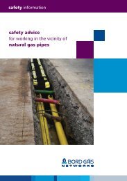
Recessed meter box<br />
Figure 1:<br />
Gas meter box be<strong>for</strong>e <strong>and</strong><br />
after meter being fitted<br />
Figurer 2:<br />
Typical detail of pipe through Cavity Wall<br />
Insulation<br />
Recessed<br />
Meter Box<br />
DPC<br />
Pipe clip<br />
Concrete floor slab<br />
All pipe joints must<br />
be outside the sleeve<br />
Ground Leve<br />
Sleeve<br />
25mm min.<br />
Piping in concrete<br />
must be protected<br />
from corrosion with<br />
wrap or PVC coating<br />
Polystyrene<br />
insulation<br />
Foundation<br />
3
Natural Gas pipework<br />
Gas installation pipework<br />
This section of the <strong>Bord</strong> Gáis Technical Manual Booklet<br />
2 refers to gas installation pipework in a traditional<br />
domestic building. This guide has been prepared to<br />
reflect the requirements of I.S. 813:2002 ‘Domestic<br />
Gas Installations <strong>and</strong> I.S. EN 1775 1998.<br />
For <strong>guidelines</strong> to installing Natural Gas to multioccupancy<br />
dwellings i.e. apartments, please refer to<br />
Booklet 3.<br />
Any person installing natural gas must be a registered<br />
gas installer <strong>and</strong> do so in accordance with I.S. 813<br />
‘Domestic Gas Installations’. This guide prepared by<br />
<strong>Bord</strong> Gáis is intended to assist <strong>installers</strong> but is not to be<br />
used as an alternative to the most up to date edition of<br />
I.S.813.<br />
Where gas pipework may be confused with other<br />
pipework, it must be colour coded bright yellow<br />
(Yellow ochre - 08 C 35), indelibly marked along its<br />
entire length with the word “GAS”/Marking tape.<br />
General<br />
Gas pipework is installed in a dwelling in order to<br />
convey gas in a safe manner from the point where<br />
delivery is made by <strong>Bord</strong> Gáis (usually at the meter)<br />
to connect to the various appliances, which may be<br />
installed inside or outside the dwelling.<br />
In designing <strong>and</strong> installing domestic pipework every<br />
ef<strong>for</strong>t should be made to ensure that it <strong>for</strong>ms a<br />
robust, serviceable element constructed within the<br />
dwelling <strong>and</strong> will continue to be serviceable <strong>and</strong><br />
safe <strong>for</strong> a period not less than the expected life of<br />
other services within the building.<br />
Typical appliances which could be provided <strong>for</strong><br />
when installing pipework, include:<br />
• Central Heating Boiler<br />
• Water Heater<br />
• Cooker/Oven/Hob<br />
• Tumble Dryer<br />
• Barbeque<br />
• Living Flame Fire<br />
• Decorative Lighting<br />
4
Pipe materials<br />
Piping materials should be selected by considering<br />
mechanical strength, appearance, corrosion potential<br />
<strong>and</strong> cost. Copper tubing is normally used <strong>for</strong> residential<br />
gas installation piping. Corrosion protected steel<br />
should be considered in external locations where<br />
impact damage is a risk.<br />
Table 1:<br />
Suitable materials <strong>for</strong> external <strong>and</strong> internal installation pipework<br />
Material<br />
Rigid Copper Tubing<br />
Soft Copper Tubing<br />
C.S.S.T<br />
Mild Steel Pipe (coated)<br />
Polyethylene Pipe<br />
Location<br />
Internal / External<br />
External / Below ground only<br />
Specifications<br />
BS 2871 Table 4 or Equivalent<br />
BS 2871 Table 4 or Equivalent<br />
BS 7838<br />
BS 1387 table 5 or Equivalent<br />
EN 1555<br />
Note Polyethlene Pipe may not be brought within<br />
any dwelling. If brought above ground, polyethylene<br />
pipework must be protected against uv light, impact<br />
<strong>and</strong> sources of <strong>heat</strong>. (See figure 11).<br />
Be Aware !<br />
Polyethylene (PE) pipe has an extremely low<br />
melting point. Take care when soldering near PE<br />
pipe.<br />
Pipe Sizing<br />
Pipework <strong>for</strong> domestic installations should be sized<br />
to meet the maximum combined flow rate <strong>for</strong> all the<br />
appliances installed.<br />
Be Aware !<br />
The maximum pressure loss between the meter<br />
outlet <strong>and</strong> any appliance should not exceed 1<br />
mbar (with all appliances in normal use).<br />
If the maximum consumption of<br />
all appliances is greater than 6m 3 /hr, then a<br />
larger meter than the st<strong>and</strong>ard domestic meter is<br />
required. Please contact <strong>Bord</strong> Gáis.<br />
Remember<br />
• Keep elbows <strong>and</strong> tees to a minimum.<br />
• Each elbow or branch connection is equivalent to<br />
about 0.5m of straight pipe.<br />
• Use machine or spring <strong>for</strong>med bends wherever<br />
possible.<br />
Tables 2 & 3:<br />
Typical appliance consumption <strong>and</strong> conversion factors<br />
Typical appliance Consumptions<br />
Conversion Factors<br />
Domestic Boiler<br />
Cooker<br />
Dryer<br />
Gas Fire<br />
2.00m 3 /hr approx<br />
1.00m 3 /hr approx<br />
0.50m 3 /hr approx<br />
0.75m 3 /hr approx<br />
1.00m 3 Nat. Gas = 11kW approx<br />
1.00m 3 Nat. Gas = 37,500 Btu/hr approx<br />
1kW = 3,412 Btu/hr<br />
5
Table 4:<br />
Pipe sizing <strong>for</strong> copper tubing source: I.S.813: 2002<br />
length<br />
m<br />
Tube Diameter mm - Copper<br />
6 8 10 12 15 22 28<br />
m 3 /h Heat m 3 /h Heat m 3 /h Heat m 3 /h Heat m 3 /h Heat m 3 /h Heat m 3 /h Heat<br />
input input input input input input input<br />
kW kW kW kW kW kW kW<br />
3 0.13 1.5 0.57 6.6 1.11 12.9 1.65 19.1 3.2 37 9.6 111 19.8 230<br />
6 0.07 0.8 0.29 3.3 0.69 8.0 1.10 12.8 2.1 24 6.4 74 13.2 153<br />
9 0.04 0.5 0.19 2.2 0.56 6.5 0.94 10.8 1.7 19 5.1 59 10.3 120<br />
12 0.03 0.4 0.14 1.7 0.52 6.1 0.90 10.5 1.4 17 4.3 50 8.8 102<br />
15 0.03 0.3 0.11 1.3 0.43 5.0 0.76 8.8 1.2 14 3.7 43 7.7 89<br />
20 0.02 0.2 0.08 0.9 0.32 3.8 0.57 6.6 1.0 12 3.2 37 6.5 75<br />
25 0.02 0.2 0.07 0.8 0.26 3.0 0.45 5.2 1.0 12 2.8 32 5.7 66<br />
30 0.01 0.1 0.06 0.6 0.21 2.5 0.37 4.3 1.0 11 2.5 29 5.2 60<br />
40 0.01 0.1 0.03 0.4 0.16 1.9 0.29 3.3 0.7 8 2.1 24 4.3 50<br />
Note: 1mBar = 10 N/m 2 = 0.1kPa<br />
Effective capacity of a copper tube installation with 1.0<br />
mbar difference between the ends <strong>for</strong> a gas of relative<br />
density 0.6 (air = 1)<br />
Table 5:<br />
Pipe sizing <strong>for</strong> mild steel source: I.S.813: 2002<br />
length<br />
m<br />
Tube Diameter mm - Mild Steel<br />
(Natural Gas)<br />
6 8 10 12 15 22 28<br />
m 3 /h Heat m 3 /h Heat m 3 /h Heat m 3 /h Heat m 3 /h Heat m 3 /h Heat m 3 /h Heat<br />
input input input input input input input<br />
kW kW kW kW kW kW kW<br />
3 0.32 3.7 0.88 10.2 2.31 26.8 1.65 19.1 4.7 55 14.3 166 29.7 345<br />
6 0.15 1.8 0.58 6.8 1.54 17.9 1.10 12.8 3.2 37 9.6 112. 20.3 235<br />
9 0.10 1.1 0.54 6.3 1.21 14.0 0.94 10.8 2.5 29 7.9 92 16.2 188<br />
12 0.08 0.9 0.40 4.6 1.02 11.9 0.90 10.5 2.2 26 6.7 78 13.8 160<br />
15 0.06 0.6 0.32 3.7 0.89 10.3 0.76 8.8 1.9 22 5.9 68 12.3 142<br />
20 0.04 0.5 0.24 2.8 0.77 8.9 0.57 6.6 1.7 19 5.0 57 10.6 122<br />
25 0.03 0.4 0.19 2.2 0.76 8.8 0.45 5.2 1.5 18 4.4 51 9.2 106<br />
30 0.03 0.3 0.15 1.8 0.63 7.3 0.37 4.3 1.4 17 3.9 45 8.3 97<br />
40 0.02 0.2 0.12 1.4 0.47 5.5 0.29 3.3 1.3 15 3.3 39 7.0 82<br />
Note: 1mBar = 10 N/m 2 = 0.1kPa<br />
Effective capacity of a steel pipe installation with 1.0<br />
mbar difference between the ends <strong>for</strong> a gas of relative<br />
density 0.6 (air = 1)<br />
6
Table 6:<br />
Pipe sizing <strong>for</strong> polyethylene pipe source: I.S.813: 2002<br />
length<br />
m<br />
Tube Diameter mm - Polyethylene<br />
(Natural Gas)<br />
25 mm 32 mm 63 mm<br />
Heat m 3 /h Heat m 3 /h Heat m 3 /h<br />
input input input<br />
kW kW kW<br />
3 97.1 8.4 189.9 16.4 1144.9 98.7<br />
6 65.0 5.6 127.6 11.0 774.9 66.8<br />
9 51.4 4.4 100.9 8.7 616.0 53.1<br />
12 43.4 3.7 85.5 7.4 523.2 45.1<br />
15 38.0 3.3 75.1 6.5 460.6 39.7<br />
18 34.2 2.9 67.5 5.8 415.1 35.8<br />
21 31.8 2.7 61.7 5.3 380.1 32.8<br />
24 30.6 2.6 57.1 4.9 352.2 30.4<br />
Note: 1mBar = 10 N/m 2 = 0.1kPa<br />
Discharge in a straight horizontal polyethylene pipe<br />
with 1.0 mbar difference between the ends, <strong>for</strong> gas of<br />
relative density 0.6 (air = 1)<br />
Note:<br />
1. The above tables refer to Natural Gas only.<br />
Should an installation be on a temporary<br />
supply from an LPG tank, awaiting<br />
connection of Natural Gas, the above<br />
tables must be adhered to.<br />
2. For further details in relation to pipe sizing,<br />
please consult the CIBSE Guide Section C4<br />
7
Jointing of pipes<br />
Solder Joints<br />
Flux should be used sparingly <strong>and</strong> only applied to the<br />
spigot part of the joint.<br />
The joint should not be over<strong>heat</strong>ed.<br />
Residual flux should be wiped from joints after being<br />
made.<br />
It is known that fluxed, unsoldered joints may satisfy<br />
the soundness test, there<strong>for</strong>e, finished joints should<br />
always be visually examined to confirm that the solder<br />
has run.<br />
When making screwed joints, all threads should be<br />
clean <strong>and</strong> undamaged.<br />
The preferred method of jointing is to use the correct<br />
PTFE tape complying with either. BS 4375 or BS 6974.<br />
Be Aware !<br />
• White lead based paste is not allowed<br />
• Hemp can only be used with paste complying<br />
with BS 6956.<br />
Sources of ignition<br />
When making solder joints extreme care should be<br />
taken when using a blow lamp or power tool in the<br />
vicinity of combustible materials. Adequate protection<br />
must be used when working near timber components<br />
<strong>and</strong> bitumised products <strong>and</strong> polyethylene pipework.<br />
Figure 3:<br />
Correct protection of back-ground material when<br />
coldering copper<br />
Hemp should only be used on threaded joints in<br />
conjunction with thread sealing paste.<br />
If <strong>for</strong> any reason paste is being used then it must<br />
comply with BS 6956.<br />
Liquid detergent should never be used when leak<br />
testing, it can cause rapid corrosion of copper.<br />
Mechanical Joints<br />
The use of union joints, compression fittings or<br />
screwed joints is ONLY acceptable where they will<br />
be readily accessible to allow correct tightening <strong>for</strong><br />
a sound joint. They should not be used in concealed<br />
locations eg. ducts, underfloor, etc.<br />
Copper Tube<br />
Tube ends should be cut square <strong>and</strong> any burrs, internal<br />
or external, removed. Tube lengths should be checked<br />
<strong>and</strong> cleared of any <strong>for</strong>eign matter be<strong>for</strong>e use.<br />
Be Aware !<br />
Breather membrane in the cavity of timber<br />
framed houses or the styrofoam insulation in<br />
the cavity of block / brick dwellings is particularly<br />
vulnerable <strong>and</strong> once ignited can spread quickly<br />
within the cavity. Rectification could involve<br />
complete dismantling of the wall with serious<br />
cost implications <strong>for</strong> the installer.<br />
Screwed Joints<br />
When making screwed joints, all threads should be<br />
clean <strong>and</strong> undamaged.<br />
Hemp should only be used on threaded joints in<br />
conjunction with thread sealing compounds.<br />
When jointing paste is used, it must comply with<br />
B.S. 6956 <strong>and</strong> should only be applied to the external<br />
thread. Excess paste should be wiped away on<br />
completion of the joint. Specially compounded jointing<br />
pastes must be used <strong>for</strong> Natural Gas - white lead based<br />
pastes are not acceptable.<br />
8
Pipework protection<br />
Mechanical<br />
Protection against physical damage <strong>and</strong> corrosion must<br />
be provided where circumstances dictate. Copper tube<br />
should only be considered where mechanical damage<br />
is unlikely or where it will be enclosed in a mechanically<br />
strong protective cover.<br />
Corrosion<br />
Steel pipes run externally or in damp areas will require<br />
protection against corrosion. Copper tube will not<br />
normally require corrosion protection when run<br />
externally. When supporting pipework externally on a<br />
horizontal / vertical surface the support brackets must<br />
ensure that the pipework remains clear of the surface.<br />
Any metallic pipework run underground, embedded<br />
in a solid floor / wall or in any other corrosive location<br />
should be protected against corrosion by one of the<br />
methods shown below.<br />
Fire<br />
Pipework material, jointing methods <strong>and</strong> locations<br />
should be chosen in order to minimise the risk of a fire<br />
in the building causing a pipework failure which might<br />
add to the extent of the fire.<br />
Protective Wrapping<br />
Tape wrapping is normally used at joints or on short<br />
lengths. Any tape wrapping applied should extend at<br />
least 25mm beyond the surface of the material likely<br />
to cause corrosion. All surfaces should be clean <strong>and</strong><br />
dry be<strong>for</strong>e the tape protection is applied. An overlap of<br />
50% is required to provide a layer of double thickness.<br />
Be Aware !<br />
Bends <strong>and</strong> joints on factory coated pipe should<br />
be further protected by wrapping with a suitable<br />
plastic tape.<br />
Figure 4:<br />
Methods of pipe protection<br />
Place the pipe in a non-corrodible sleeve or duct (vent<br />
to ventilated area)<br />
Pipe with a factory bonded coating of PVC<br />
Pipe wrapped with corrosion resistant tape<br />
9
Protection<br />
Sleeves<br />
Pipes passing through external, load bearing <strong>and</strong> cavity<br />
walls should take the shortest route <strong>and</strong> be sleeved<br />
through the cavity.<br />
The purpose of a sleeve is to:<br />
• Prevent access gas entering a vulnerable space<br />
(e.g. cavity wall) in the event leakage.<br />
• To protect the gas installation pipe against<br />
corrosion.<br />
• To protect the gas installation pipe from damage<br />
by normal building movement.<br />
• To accommodate normal expansion <strong>and</strong><br />
contraction of the pipework.<br />
Sleeve Material<br />
Sleeves should be made of a material capable of<br />
containing gas. Suitable materials include polyethylene,<br />
PVC, steel <strong>and</strong> copper. The selection of the sleeve<br />
material should reflect the need <strong>for</strong> mechanical<br />
strength corrosion resistance <strong>and</strong> / or fire retardance<br />
where required.<br />
Size of Sleeve<br />
The sleeve should be of a diameter that provides a<br />
loose fit to the pipe allowing normal pipe expansion /<br />
contraction.<br />
Be Aware !<br />
Pipes / sleeves of dissimilar metal (steel to copper)<br />
should not contact at ANY point.<br />
Sealing of Sleeves<br />
Sleeves should always be sealed to the surrounding<br />
structure with a suitable building material (e.g. mastic,<br />
mortar, etc.).<br />
When gas pipes enter through an outside wall, the gap<br />
between the pipe <strong>and</strong> the sleeve should be sealed to<br />
the pipe at the inner end of the sleeve only with a<br />
flexible, fire resisting compound. (See figure 29, page<br />
26).<br />
Sleeves through internal walls should be sealed to the<br />
pipe at entrance <strong>and</strong> exit. (See detail below).<br />
Be Aware !<br />
Pipework within a sleeve should not be jointed.<br />
Figure 5:<br />
Details of pipe sleeve through cavity wall<br />
Insulation<br />
Grout<br />
Any joint must be<br />
outside the sleeve<br />
Sleeve<br />
10
Pipework from the meter to the building.<br />
Provision of customer isolation valves<br />
on extended pipework runs:<br />
Figure 6:<br />
Locating isolating values<br />
<strong>for</strong> terraced houses<br />
Hse 1<br />
Hse 2<br />
Hse 3<br />
Wall<br />
Hse 4<br />
Meter Box or<br />
Cabinet<br />
Meter Box<br />
Figure 7:<br />
Locating isolating values<br />
<strong>for</strong> duplex units<br />
Upper Duplex Unit<br />
(See page 22)<br />
Ground Floor Unit<br />
Figure 8:<br />
Locating isolating<br />
values in apartments<br />
6 Meter Cabinet<br />
External Riser<br />
Internal Rising Duct<br />
Note:<br />
Regardless of the route<br />
taken by installation<br />
pipework from meter<br />
to each dwelling, the<br />
pipework must be fitted<br />
with a customer isolation<br />
valve as soon as the pipe<br />
enters the dwelling that<br />
it is supplying.<br />
Meter<br />
Manifold<br />
Meter<br />
Manifold<br />
Ground Level<br />
See booklet 3<br />
pages 17 <strong>and</strong> 18.<br />
Naturally Ventilated Basement<br />
11
Installation pipework from the meter<br />
Pipework should be protected against<br />
corrosion preferably by using pipes with<br />
a factory applied PVC coating. Where<br />
copper pipes are run externally exposed<br />
to the elements but supported clear of<br />
other surfaces, corrosion protection is not<br />
normally necessary. Consult page 9 <strong>for</strong><br />
further considerations.<br />
Pipework should not be installed under<br />
the foundations of a building nor in the<br />
ground under the base of a wall footing<br />
or foundation.<br />
Be Aware !<br />
All underground pipework should be pressure tested be<strong>for</strong>e<br />
initial wrapping or covering takes place.<br />
Installation pipework under concrete paths, (pedestrian traffic only),<br />
should have:<br />
• Minimum cover of 25mm between sleeve / wrapping <strong>and</strong><br />
concrete finish, (see figure 9 below).<br />
• Pipework must be placed in sleeve or have protective wrapping.<br />
Figure 9:<br />
Meter on adjacent wall<br />
(pipework beneath footpath)<br />
Meter Box<br />
Protective cover<br />
25mm<br />
cover min.<br />
Footpath<br />
Buried pipework in open soil, lawns, or under gravel paths, areas<br />
which can be accessed by vehicle should have:<br />
• Minimum trench depth of 375mm.<br />
• Minimum s<strong>and</strong> or fine fill surround required in trench of<br />
150mm.<br />
• When area can be accessed by vehicle (under tarmac,<br />
cobblestone, etc.), the pipework must also have a protective<br />
sleeve, (see figure 10 above).<br />
Figure 10:<br />
Meter on adjacent wall<br />
(pipework beneath soft<br />
ground or vehicular traffic)<br />
Meter Box<br />
375 mm<br />
min. cover<br />
Protective<br />
sleeve<br />
12
Polyethylene pipework<br />
Polyethylene (PE) Gas installation piping -<br />
Underground<br />
PE piping can be used <strong>for</strong> underground supply of gas<br />
to a premises <strong>and</strong> is a convenient alternative to metallic<br />
pipes when used externally.<br />
External buried PE pipework shall be constructed as<br />
follows:<br />
• Mechanical fittings in accordance with I.S. 265<br />
can be used on buried PE pipework.<br />
• Any metallic joints must be wrapped with a<br />
minimum of two layers.<br />
• PE pipework must be tested to ensure it is gas<br />
tight be<strong>for</strong>e being covered.<br />
• Pipework in soil should be bedded in s<strong>and</strong> or fine<br />
filling to a depth of 150mm above <strong>and</strong> below the<br />
pipe. The minimum depth of cover of the pipe<br />
required is 375mm.<br />
Any installer engaging in<br />
• Welding<br />
• Electrofusion<br />
• Pipework insertion by mole or horizontal drilling<br />
in compliance with I.S. 265 should be suitably trained<br />
<strong>and</strong> certified (GDF1 or equivalent).<br />
Be Aware !<br />
PE pipework should not be laid above 375mm<br />
dept of cover regardless of cover material.<br />
• Pipework, which may be subject to vehicular<br />
loading eg. under cobble lock driveway, should<br />
be, in addition to the minimum depth of cover<br />
of 375mm, enclosed in a protective sleeve.<br />
Be Aware !<br />
• Polyethylene pipe is not allowed within a<br />
building.<br />
For correct method of entry into building above<br />
ground level, see figure 11 below.<br />
For correct method of entry into building below<br />
ground level, see figure 12 over-leaf.<br />
Figure 11:<br />
Polyethylene-metal transition<br />
(supply entering building<br />
above ground level)<br />
GRP cover<br />
fixed to wall<br />
Above ground<br />
fitting<br />
Capillary<br />
soldered elbow<br />
Suitably sized<br />
copper pipe<br />
GRP sleeve<br />
GRP sleeve bend<br />
GRP sleeve<br />
bend<br />
Note:<br />
PE from<br />
meter<br />
Both GRP sleeve <strong>and</strong> GRP cover<br />
must be used on this section.<br />
13
Figure 12:<br />
Polyethylene-Metal transition (supply<br />
entering building below ground)<br />
External Leaf<br />
375mm minimum<br />
dept of cover<br />
PVC coated copper<br />
Anti-shear sleeve<br />
300mm min.<br />
PE<br />
from<br />
meter<br />
PE pipe<br />
Polyethylene / Metal<br />
transition fitting (Two<br />
layers of protective<br />
wrapping required)<br />
Figure 13:<br />
Below-ground transition fitting with anti-shear sleeve<br />
Below-Ground transition<br />
fitting<br />
Below-Ground transition fitting with<br />
Anti-shear sleeve.<br />
Note:<br />
The polyethylene-metal transition must be suitable<br />
<strong>for</strong> below ground applications, always consult the<br />
supplier.<br />
The anti-shear sleeve must be fitted at all times<br />
when placing transition beneath the ground.<br />
14
Pipes laid in floors<br />
Where the piping is to be laid on a solid floor slab, the<br />
finished floor screed must allow 25mm minimum cover<br />
over the installed pipe.<br />
Figure 14:<br />
Pipe run on solid floor slab<br />
Floor covering<br />
Screed<br />
25 mm<br />
minimum<br />
Solid or screeded floors<br />
Pipework laid in solid floors should be:<br />
• Tested <strong>for</strong> soundness be<strong>for</strong>e any<br />
protective coating or cover is applied.<br />
• Protected against corrosion e.g. factory bonded<br />
PVC. see fig 15<br />
• Adequately embedded by at least 25mm below<br />
the final floor finish.<br />
• Sleeved <strong>and</strong> taken the shortest practicable route<br />
when passing vertically through a solid floor. see<br />
fig 16.<br />
Floor slab<br />
Figure 15:<br />
Pipe with factory bonded PVC<br />
Be Aware !<br />
Compression fittings, screwed joints shall<br />
not be used on internal buried metallic<br />
pipework.<br />
All joints should be kept to a minimum<br />
Figure 16:<br />
Sleeving pipework vertically<br />
through floors<br />
Fire resistant<br />
mastic<br />
Sleeve<br />
Fire resistant<br />
mastic<br />
15
Pipes laid in floors<br />
Suspended floors<br />
Prior to running pipework below suspended<br />
floors, a visual inspection should be carried<br />
out to note the position of any electrical<br />
cables, junction boxes <strong>and</strong> ancillary<br />
equipment, in order to safely route the gas<br />
pipes.<br />
Figure 17:<br />
Compression fittings.<br />
Be Aware !<br />
Compression fittings can not be used when pipes are<br />
placed beneath / within floors or in inaccessible positions.<br />
Where pipes are installed between joists, they<br />
should be correctly supported in accordance<br />
with the following table:<br />
Table 7:<br />
Support distances <strong>for</strong> horizontal runs of<br />
pipe in suspended floors.<br />
Material Normal size (mm) Interval Horisontal Run (m)<br />
Copper Up to 15 1.2<br />
22 1.8<br />
28 1.8<br />
Mild Steel Up to 15 2<br />
20 2.5<br />
25 2.5<br />
Where pipes are laid across joists fitted with floor<br />
boards or flooring grade chipboard, the pipe should<br />
be located in purpose made notches or circular holes<br />
drilled through the joists.<br />
Figure 18:<br />
Notching or providing holes in joists<br />
Max. D/7<br />
Min. S/14<br />
Max. S/4<br />
Timber Joist<br />
Depth (D)<br />
Span (S)<br />
Support wall<br />
Support wall<br />
Max. Diameter d = D/4<br />
Min. S/14<br />
Max S/4<br />
Depth (D)<br />
C L C<br />
Support<br />
wall<br />
Min. distance between hole centres - 3d<br />
Span (S)<br />
Support wall<br />
16
Pipes laid in floors<br />
Timber floors<br />
Notches should not be made in joists of less than<br />
100mm depth. The depth of any notch should be<br />
sufficient to accommodate fully the pipe or fittings, but<br />
should not exceed 15% (approximately one seventh)<br />
of the joist depth. The notch should be located not<br />
further than one quarter of the span from an end<br />
support; it should be U-shaped when possible <strong>and</strong><br />
no wider than necessary to accommodate the pipes.<br />
Notches should not extend across the joint between<br />
the floor boards.<br />
Be Aware !<br />
Care should be taken when re-fixing floor boards<br />
to prevent damage to the pipes by nails or<br />
screws.<br />
Location of under floor pipes should be marked on<br />
floor boards using pencil / marker or rotary stamp.<br />
Figure 19:<br />
Marking areas where pipes are laid<br />
Laying pipes<br />
Care should be taken to prevent the ingress of dirt <strong>and</strong><br />
water etc. into the pipes. The bore should be examined<br />
be<strong>for</strong>e installation <strong>and</strong> the open ends temporarily<br />
sealed or plugged prior to running the pipes through<br />
dirty areas, <strong>for</strong> example, below floor boards, (see detail<br />
below)<br />
Figure 20:<br />
Preventing the ingress of dirt / water within feeding<br />
pipework though concealed spaces<br />
17
Vertical pipe runs<br />
Particular care is required to ensure that pipes hidden<br />
in walls do not become a risk due to accidental<br />
damage or structural damage due to building<br />
settlement. The ingress of gas into voids or cavities<br />
must be avoided.<br />
Protection<br />
Where pipework is to be chased into a solid wall, it is<br />
of particular importance that high quality corrosion<br />
protection is applied, preferably factory bonded PVC.<br />
This is to ensure that high levels of moisture within the<br />
wall do not have any detrimental corrosive effect on<br />
the pipework.<br />
Vertical Pipe Runs (Only)<br />
It is not acceptable <strong>for</strong> pipework to be run horizontally<br />
or at any angle other than vertically in a wall chase.<br />
Figure 21:<br />
Permitted direction of wall chase (vertical only)<br />
Pipes in solid walls<br />
Vertical pipes should be placed in ducts on the wall<br />
surface with convenient access. If this is not practical,<br />
the pipework may be chased into the wall provided<br />
that the depth of the chase does not exceed one third<br />
of the depth of the block or brick. In this situation, the<br />
pipe should be protected against corrosion.<br />
Be Aware !<br />
Such chasing is unlikely to be achieved in walls<br />
constructed of ‘hollow’ blocks.<br />
18
Gas pipework behind Dry lined walls<br />
The installation pipework within dry lined walls should<br />
be run within purpose designed channels providing<br />
adequate protection, ie. metal protection where<br />
required.<br />
Where it is not possible to do this, then it is acceptable<br />
to run the pipe on the wall surface behind the dry<br />
lining provided that the pipe is:<br />
Be Aware !<br />
Compression/mechanical fittings can not be<br />
used when pipes are placed behind plasterboard<br />
or in inaccessible positions.<br />
• Securely fixed <strong>and</strong> supported.<br />
• Joints are kept to an absolute minimum.<br />
• The pipe is protected against corrosion.<br />
• The pipe is protected against mechanical damage,<br />
(see details below).<br />
Figure 22:<br />
Details of pipework behind dry lining<br />
PVC Coated Copper<br />
Protective 18 swg steel cover<br />
Pipe in wall behind dry lining<br />
PVC Coated Copper<br />
Protective 18 swg steel cover<br />
Pipe in channel behind dry lining<br />
19
Timber framed walls<br />
The following issues need to be addressed when<br />
considering running gas pipework within the walls of<br />
timber framed construction:<br />
• Possible interference with or weakening of<br />
structure members of the house frame.<br />
• Possibility of inadvertent damage to pipework<br />
when using plasterboard or other fixings to the<br />
inner timber leaf.<br />
• Possibility, in the event of a gas escape that:<br />
• a dangerous accumulation could occur or<br />
• the gas might migrate into the<br />
outer cavity, be<strong>for</strong>e the escaping gas is<br />
smelled by the occupant.<br />
• Possibility that natural movement of the structure<br />
could damage the pipe.<br />
One of the following options, chosen at design stage,<br />
can be used to ensure the avoidance of the possibilities<br />
listed above.<br />
Option 1<br />
Run pipework (* rigid or flexible) in floor slab <strong>and</strong> exit<br />
from the floor to the appliance in front of the finished<br />
plasterboard face of the wall - see figure 23 below.<br />
Be Aware !<br />
*Compression joints are not permitted in slab.<br />
Option 1A<br />
Run pipework as above but exit from the floor into a<br />
separately constructed channel to exit at the appliance.<br />
This channel must not allow gas to move into the<br />
timber frame or cavity. Termination must be in front of<br />
the finished plasterboard face of the wall.<br />
Option 2<br />
All pipework to be run on exposed internal wall<br />
surface or in plastic ducting on wall surface or within<br />
cupboards.<br />
Figure 23:<br />
Appliance connection in front of timber leaf<br />
Plasterboard<br />
Recessed Gas Meter Box<br />
Concrete floor slab<br />
External<br />
Brick / Block Leaf<br />
25mm min.<br />
Piping in concrete<br />
protected from<br />
corrosion with wrap<br />
or PVC coating<br />
Sleeve<br />
Ground level<br />
Polystyrene insulation<br />
Copper joint must be<br />
outside sleeve<br />
20
Timber Framed Walls<br />
Option 3<br />
Run pipework in timber frame walls using continuous<br />
plastic coated soft copper or stainless steel - see<br />
figure 24. If copper is used, a protective metal cover<br />
must be placed in front of the pipework.<br />
Timber framed construction of the inner wall requires<br />
particular consideration when it is proposed to run<br />
gas installation pipework within it. This should only<br />
be considered as a last resort, prefered options are<br />
described on the previous page.<br />
Where there is no other option, gas installation<br />
pipework may be laid within the timber frame<br />
construction provided the following is adhered to:<br />
• Any gas pipe run should be kept to a minimum<br />
<strong>and</strong> run vertically within purpose designed<br />
channels.<br />
• Channels should be fitted with insulation <strong>and</strong><br />
covered with the vapour barrier <strong>and</strong> plasterboard<br />
to the same st<strong>and</strong>ard as the rest of the wall.<br />
• Gas pipes should be adequately supported on the<br />
studs.<br />
• Pipe joints should be kept to an absolute<br />
minimum.<br />
• Compression fittings must not be used.<br />
• Studs should not be notched. Holes in studs<br />
<strong>and</strong> holes <strong>and</strong> notches in horizontal timber /<br />
membranes should be kept as small as possible.<br />
• Pipes should be coated copper or steel to avoid<br />
corrosion.<br />
• Where copper pipes are used, they should be<br />
enclosed within a 18 swg steel sheet or equivalent<br />
metal plate. (See figure 24). Alternatively,<br />
mild steel pipes may be used without further<br />
mechanical protection. But full corrosion<br />
protection is required.<br />
• Provision should be made <strong>for</strong> the pipe to<br />
accommodate any normal movement of the<br />
building.<br />
• Where the gas supply point is to be positioned on<br />
a separating (party) wall, the pipe should rise in<br />
front of the finished plasterboard face.<br />
Be Aware !<br />
• Pipes must not be laid within separating<br />
(party) walls dividing individual dwellings.<br />
21
Figure 24:<br />
Full storey height riser in timber framed walls<br />
Full storey height riser<br />
Continuous PVC<br />
Coated Copper<br />
No mechanical<br />
fittings permitted<br />
100 mm<br />
Metal cover<br />
A<br />
A<br />
Section A-A<br />
Figure 25:<br />
Appliance connection point to the front of timber<br />
framed walls<br />
Appliance connection-point riser<br />
PVC Coated<br />
Copper<br />
Appliance<br />
connection point<br />
Additional noggins<br />
required <strong>for</strong> support<br />
100 mm<br />
A<br />
A<br />
22
Internal pipework ducts<br />
For Apartment Installation Guidelines:<br />
Please consult Booklet 3<br />
For installation of Gas within Duplex<br />
units:<br />
Please use external risers as per page 11 of<br />
Booklet 3. If an external riser can not be<br />
facilitated, it is recommended that an internal<br />
“filled” duct is used (as per page 16, Booklet 3).<br />
Figure 26:<br />
Internal ventilated duct<br />
Internal<br />
ventilated<br />
duct<br />
PVC coated copper<br />
or steel pipework<br />
Fire resistant<br />
material<br />
Gas pipes should not be fitted in lift shafts or protected<br />
shafts or in any space where gas could migrate in<br />
openings to those shafts.<br />
Building services shafts containing compressed air,<br />
steam or air conditioning ducts should not be used as<br />
a route <strong>for</strong> gas pipes.<br />
For further details on the interaction of natural gas<br />
pipework <strong>and</strong> other services, please consult Booklet 3<br />
of this guide, page 20.<br />
Vertical or horizontal purpose-laid ducts, containing<br />
pipework, should be ventilated at the top <strong>and</strong> bottom<br />
with an open grille (see fig 26). These vents to the duct<br />
must have a free area of 5,000mm2 or 1/500th the<br />
cross sectional area of the duct, which ever is greater.<br />
The purpose of the vents is to ensure that any escape<br />
of gas can transmit to a non-hazardous area <strong>and</strong> be<br />
detected by smell.<br />
23
Pipe Supports <strong>and</strong> fixings<br />
Figure 27:<br />
Support of pipework to prevent corrosion caused by<br />
contact with aggressive surfaces<br />
All pipework should be adequately supported to<br />
prevent the pipework from coming into contact<br />
with surfaces that are likely to cause corrosion (e.g.<br />
concrete, masonry, plaster). Supports made from<br />
plastic are generally acceptable.<br />
Be Aware !<br />
Ferrous materials e.g. screws <strong>and</strong> support brackets<br />
shall not be in contact with copper piping.<br />
Table 8:<br />
Supporting pipework (Horizontally <strong>and</strong> vertically)<br />
Pipe Support Distance<br />
Material Normal size Interval <strong>for</strong> vertical run Interval <strong>for</strong> horizontal run<br />
(mm) (m) (m)<br />
Copper Up to 15 2.0 1.2<br />
22 2.5 1.8<br />
28 2.5 1.8<br />
35 3.0 2.5<br />
42 3.0 2.5<br />
54 3.0 2.7<br />
Mild steel Up to 15 2.5 2.0<br />
20 3.0 2.5<br />
25 3.0 2.5<br />
32 3.0 2.7<br />
40 3.5 3.0<br />
50 3.5 3.0<br />
24
Gas meters <strong>and</strong> electrical elements.<br />
Pipework should not be installed closer than 150mm to<br />
an electricity meter. When this is not possible, a nonconductive<br />
shield should be placed between the pipe<br />
<strong>and</strong> the electrical equipment providing the required<br />
separation distance.<br />
Gas meters shall not be located above or below nor<br />
closer than 400mm to an electrical distribution board.<br />
Pipework should be installed at least 25mm away from<br />
the electricity supply, distribution cables. Otherwise<br />
an appropriate electrical insulation material should<br />
be wrapped around the pipe to prevent arcing. Gas<br />
pipework should always be separated by a minimum of<br />
10mm from other metal piped services.<br />
Note:<br />
Subject to approval from electricity supplier.<br />
Figure 28:<br />
Installation in relation to electrical meters etc.<br />
Electricity meter<br />
150mm Min.<br />
Non-conductive partition<br />
150mm<br />
min.<br />
Electricity meter<br />
25
Electrical cross bonding of supply<br />
pipework<br />
For meters installed in external meter boxes, the<br />
bonding connection should be as near as practicable<br />
to the point of entry. Bonding wires should not be<br />
connected in the meter box.<br />
Figure 29:<br />
External Meter (Cross bonding)<br />
Bond<br />
Connection to<br />
earth must be<br />
outside meter<br />
box<br />
Pipework<br />
from meter<br />
Temperature<br />
resistant mastic<br />
Grout<br />
Figure 30:<br />
Internal Meter (Cross bonding)<br />
500 mm<br />
Max<br />
Bonding<br />
Connection<br />
In the case where the meters are installed inside the<br />
building, the bond should be located within 500mm of<br />
the meter outlet pipe.<br />
26
Electrical Cross Bonding at boiler<br />
The current edition of I.S.813: 2002 refers to some<br />
requirements, which can be found in current editions<br />
of the E.T.C.I. wiring regulations including the necessity<br />
to cross bond all ‘extraneous metal work including gas<br />
supply, water <strong>and</strong> central <strong>heat</strong>ing pipes’.<br />
Figure 31:<br />
Cross bonding<br />
arrangement near<br />
boiler<br />
Wall Mounted<br />
Gas Boiler<br />
Gas Supply C.W. H.W.<br />
Be Aware !<br />
Installers on sites should check with the<br />
building contractor that the electrician is<br />
completing all bonding work <strong>and</strong> the existence<br />
of an electrical completion certificate must<br />
be confirmed by the installer be<strong>for</strong>e issuing<br />
a Declaration of Con<strong>for</strong>mance <strong>for</strong> the gas<br />
installation (see pg 39). If the contractor on<br />
site does not confirm this, then a copy of the<br />
notice (shown below) should be affixed to the<br />
boiler be<strong>for</strong>e issue of a con<strong>for</strong>mity declaration to<br />
I.S.813: 2002.<br />
Example of Safety Notice<br />
Electrical safety - equipotential (cross) Bonding<br />
Some types of electrical installations are fitted with<br />
equipotenial bonding, which is the connection of<br />
the internal gas <strong>and</strong> water pipes to the electrical<br />
installation’s earth terminal. In particular those<br />
installations with Protective Multiple Earthing<br />
(P.M.E) should, <strong>for</strong> safety reasons, be fitted with<br />
equipotential bonding.<br />
*For in<strong>for</strong>mation contact your Electricity Supplier<br />
In the Gas Safety Installation St<strong>and</strong>ard I.S.813: 2002<br />
there is the safety in<strong>for</strong>mation that any person who<br />
carries out installation pipe work should in<strong>for</strong>m the<br />
user that electrical bonding must be checked (& if<br />
necessary rectified) by a competent person*, in any<br />
dwelling where electrical equipotential bonding may<br />
be necessary.<br />
Be Aware !<br />
Risk of Electrical shock if Working on<br />
Existing Pipework<br />
A temporary continuity bond must be used when<br />
carrying out any work on the pipework or fittings<br />
which will break electrical continuity through them.<br />
27
Appliance Connections<br />
It is necessary to provide an appliance valve within 1<br />
metre of each appliance supplied. Depending on the<br />
appliance the preferred valving methods are shown<br />
below.<br />
Be Aware !<br />
Plug type valves (gas cocks) are not permitted.<br />
Cookers<br />
Figure 32:<br />
Cooker flexible pipe connected to self-closing<br />
bayonet valve.<br />
Yellow indicates<br />
suitability <strong>for</strong><br />
Nat. Gas<br />
Hobs <strong>and</strong> ovens<br />
Figure 33:<br />
A valve may be fitted in adjacent cupboards to the left or<br />
right of the oven / hob.<br />
28
Fires<br />
Figure 34:<br />
Valve near <strong>builders</strong> opening<br />
Recessed valve located in chimney breast<br />
When installed, turn on <strong>and</strong> refit cover<br />
disk <strong>and</strong> plate<br />
Figure 35:<br />
Recessed valve - detail<br />
Ball valve with casing<br />
flush to wall surface<br />
8mm wrapped<br />
copper - 1m<br />
max. run<br />
10mm wrapped<br />
copper - 3m max. run<br />
Flush fitting ball valve <strong>for</strong> concealed gas installations<br />
All pipework to be<br />
PVC coated copper<br />
Be Aware !<br />
If not fitting the<br />
fire as st<strong>and</strong>ard:<br />
1. Do not connect<br />
or leave live gas<br />
pipework to the<br />
<strong>builders</strong> opening.<br />
or<br />
2. Turn off micropoint<br />
<strong>and</strong> cap off<br />
the downstream<br />
side of the valve.<br />
29
Central <strong>heat</strong>ing boilers <strong>and</strong> water<br />
<strong>heat</strong>ers<br />
Positioning the boiler<br />
A room sealed boiler, may be located within any room<br />
of the dwelling. If located in bathroom / shower, in<br />
an enclosed compartment or understairs, additional<br />
requirements must be adhered to. (I.S.813: 2002).<br />
Additional requirements are needed if placing a boiler<br />
beneath stairs.<br />
Be Aware !<br />
Open flue boilers are permitted in a small<br />
number of locations.<br />
See I.S.813: 2002.<br />
Lamps<br />
Figure 37:<br />
Location <strong>for</strong> valve <strong>for</strong> street lamp / garden lamp<br />
Figure 36:<br />
Boiler Valve<br />
These appliances<br />
are normally<br />
fitted with valve<br />
when supplied.<br />
Wall Mounted<br />
Gas Boiler<br />
Gas valve on supply to boiler<br />
30
External pipework<br />
External Appliances<br />
Where appliances such as barbecues, patio <strong>heat</strong>ers,<br />
<strong>and</strong> gas lights etc. are installed remote from the<br />
dwelling <strong>and</strong> the pipes are run underground,<br />
consideration should be given to installing an<br />
additional isolation valve on the supply pipe at<br />
an accessible position either internally or externally as<br />
close as possible to where the pipe exits the dwelling.<br />
The valve should be labelled showing “GAS OFF”<br />
position.<br />
Please consult figure 38 below <strong>and</strong> page 12 <strong>for</strong> pipe<br />
run requirements.<br />
Figure 38:<br />
External pipework detail<br />
House wall<br />
Barbecue<br />
Outside<br />
gas valve<br />
375 mm min.<br />
depth below grass<br />
<strong>and</strong> driveway<br />
Plastic wrapped soft<br />
copper tube<br />
150 mm s<strong>and</strong>/fine fill<br />
40 mm min. depth<br />
under concrete slabs<br />
25 mm min. depth<br />
buried in concrete<br />
Figures 39 / 40:<br />
Isolation valve <strong>and</strong> Barbecue point detail<br />
Isolation Valve<br />
Demountable connection (flexible) with integral valve.<br />
31
Permitted Flue terminal locations<br />
Flue termination<br />
<strong>guidelines</strong><br />
Irish st<strong>and</strong>ards always<br />
take precedence over<br />
manufacturers instructions,<br />
unless manufacturers<br />
instructions call <strong>for</strong><br />
additional or more strict<br />
requirements.<br />
Guttering<br />
Figure 41:<br />
Permitted locations<br />
<strong>for</strong> flue terminations<br />
Car ports shall have two<br />
open unobstructed sides<br />
All dimensions in mm<br />
Typical width 100 / 125 mm.<br />
Boiler flue<br />
termination<br />
32<br />
Sample power<br />
Flue termination
Ventilation requirements <strong>for</strong><br />
appliances<br />
All appliances require combustion air.<br />
Room-sealed appliances are provided with an air<br />
supply from outside air through a sealed pipe to the<br />
appliance, with products of combustion expelled<br />
through the flue. This, more often than not, is provided<br />
by a concentric flue arrangement.<br />
Figure 42:<br />
Recommended venting detail<br />
Be Aware !<br />
Vents must not be adjustable or capable of being<br />
closed.<br />
Be Aware !<br />
The amount of free area from the airbrick<br />
<strong>and</strong> airspace grill should be sought from<br />
manufacturer be<strong>for</strong>e fitting.<br />
Airbrick<br />
Airspace grill<br />
Sizing of vents<br />
When sizing vents the critical dimension is the amount<br />
of free area required. Physical dimensions of a vent<br />
are not of concern, but the amount of free area that<br />
is available so that air may pass through it is critical.<br />
(Note table on page 34, specific requirements <strong>for</strong> one<br />
of each type of appliance within a room).<br />
If an extraction fan, or cooker hood with an extractor<br />
fan, is fitted in the room containing an open appliance,<br />
or in a connected space to this room, the size of the<br />
vent required should be increased by 500mm2 <strong>for</strong> each<br />
30 litre per second maximum extraction fan rate.<br />
The manufacturer should have a stamp on their<br />
products showing total free area. When two or more<br />
open appliances are installed in the same compartment<br />
or space, whether or not they are supplied as a<br />
combined unit, the aggregate input rating should be<br />
used <strong>for</strong> sizing the vents.<br />
33
Table 10:<br />
Appliance ventilation requirements<br />
Appliance type <strong>and</strong> input<br />
Minimum ventilation opening<br />
(free area) required<br />
Decorative fuel effect fires 10,000mm 2<br />
Open-Flued appliance < 7kW 3,500mm 2<br />
Open-Flued appliance > 7kW <strong>and</strong> < 14kW 6,500mm 2<br />
Open-Flued appliance > 14kW <strong>and</strong> < 70kW<br />
450mm 2 per kW<br />
Fixed space <strong>heat</strong>er<br />
Permanent openings of a minimum of<br />
(e.g. flueless fire - see Case Study 9) 12,000mm 2<br />
The total ventilation required shall be equally<br />
divided between high <strong>and</strong> low level openings<br />
on the same wall, separated by a minimum<br />
distance of 1,600mm.<br />
Maximum input rate 4.2 kW<br />
(See note 2)<br />
Note 1: Rooms built in accordance with<br />
the 1997 Building Regulations TDG’s have<br />
a minimum of 6,500mm2 ventilation, or in<br />
excess of 12,000mm2 when a room contains<br />
a chimney. To allow this ventilation to count<br />
towards the minimum opening required,<br />
it must be permanently fixed in the open<br />
position.<br />
Note 2: As combustion products from this<br />
appliance are released directly into the room,<br />
additional provisions may be needed to avoid<br />
condensation <strong>and</strong> ensure satisfactory air<br />
quality. Advice should be sought from the<br />
manufacturer of the specific appliance if not<br />
included in the manufacturers instructions.<br />
Alternative vents<br />
Vents may be incorporated in window frames (Curtains<br />
must not restrict air flow) <strong>and</strong> in doors in order to<br />
satisfy the air requirement of gas appliances. The free<br />
air requirement must be stated by the manufacturer.<br />
Openings must not be adjustable or capable of being<br />
closed.<br />
34
Safety <strong>for</strong> the Home Owner<br />
Safety, certification & getting connected<br />
Important notice to all <strong>installers</strong><br />
Under current legislation <strong>Bord</strong> Gáis must be assured<br />
that an installation is safe <strong>and</strong> complies with Irish<br />
St<strong>and</strong>ard 813(I.S 813) Domestic Gas installations<br />
be<strong>for</strong>e gas can be supplied to the dwelling.<br />
It is a legal requirement under The Energy<br />
(miscellaneous provisions) Act 2006 that all “domestic<br />
gas works” must be under taken <strong>and</strong> certified by a<br />
registered gas installer (RGI) who is registered with the<br />
RGII (Register Gas Installers of Irel<strong>and</strong>)<br />
The Declaration of Con<strong>for</strong>mance Certificate ,which<br />
must be signed by the RGI carrying out the work, is a<br />
declaration by the RGI that the gas work is safe. That it<br />
has been carried out in accordance with <strong>and</strong> con<strong>for</strong>ms<br />
to the National st<strong>and</strong>ard <strong>for</strong> Domestic Gas Installations<br />
I.S.813.<br />
Only a declaration of con<strong>for</strong>mance certificate obtained<br />
from the Register of Gas Installers of Irel<strong>and</strong> (RGII) <strong>and</strong><br />
completed <strong>and</strong> signed by a RGI is acceptable <strong>for</strong> this<br />
purpose.<br />
Be Aware !<br />
If the steps outlined are not followed, in the<br />
interest of safety, the gas will not be supplied<br />
by <strong>Bord</strong> Gáis.<br />
See below.<br />
Important Notice<br />
A Registered gas Installer is only permitted to certify his / her own work or that of a registered Trainee<br />
work under supervision.<br />
The Public Listing of Registered Gas Installers is available at:<br />
www.rgii.ie<br />
35
Domestic gas installation safety<br />
In<strong>for</strong>mation <strong>for</strong> Registered Gas Installers (RGI) requiring<br />
a new meter fit.<br />
New Housing Projects<br />
A Registered Gas Installer must<br />
• Complete the entire gas installation<br />
• Issue a declaration of con<strong>for</strong>mance (post<br />
construction section)<br />
• Leave properly completed gas supplier/network<br />
operator copy on site with part one (post<br />
construction section) completed<br />
When the meter is fitted the RGI must<br />
• Connect to the gas installation<br />
• Purge installation in accordance with I.S.813<br />
• Commission appliances/installation in accordance<br />
with manufacturers requirements<br />
• Purge installation in accordance with I.S.813<br />
• Commission appliances/installation in accordance<br />
with manufacturers requirements<br />
• Complete post construction section (part 1) of<br />
declaration of con<strong>for</strong>mance<br />
• Complete part 2 of the declaration of<br />
con<strong>for</strong>mance<br />
• Issue customer with a copy of the declaration of<br />
con<strong>for</strong>mance<br />
• Return green copy to RGII within 10 days of<br />
meter fit<br />
Be Aware !<br />
Any person installing gas must be a Registered<br />
Gas Installer to do so in accordance with I.S<br />
813 “Domestic Gas Installations”<br />
• Complete part 2 of the declaration of<br />
con<strong>for</strong>mance<br />
• Issue customer copy of declaration of<br />
con<strong>for</strong>mance<br />
• Return green copy to RGII within 10 days of issue<br />
One off existing/new housing<br />
The <strong>Bord</strong> Gáis procedure <strong>for</strong> this type of installation<br />
allows <strong>for</strong> gas meters to be fitted pre-construction. If a<br />
registered gas installer requires a meter to be fitted in<br />
such circumstances then.<br />
A Registered Gas Installer must<br />
• Issue a declaration of con<strong>for</strong>mance (pre<br />
construction section)<br />
• Leave properly completed gas supplier/network<br />
operator copy on site with part one (pre<br />
construction section) completed<br />
When the meter is fitted the RGI must<br />
• Complete the installation in accordance with I.S.<br />
813<br />
• Connect to the gas meter installation (when ready<br />
<strong>for</strong> commissioning)<br />
36
Commissioning of natural gas<br />
installations<br />
Conducting a Soundness Test<br />
Be<strong>for</strong>e a declaration of con<strong>for</strong>mance is issued the<br />
R.G.I.I installer must carry out a soundness test to<br />
ensure there are no leaks in the piped system.<br />
The soundness test is carried out as follows:<br />
• All work must be carried out by a Registered Gas<br />
Installer.<br />
• Use only a pressure gauge / manometer with<br />
clearly marked 0.1 mbar gradations.<br />
• Shut off all appliance valves.<br />
• Pressurise installation with air to 100mbar (on<br />
gauge).<br />
• Wait <strong>for</strong> 5 minutes to ensure temperature<br />
stabilisation.<br />
• Check gauge / manometer <strong>and</strong> record exact<br />
marking.<br />
• After 5 minutes, check again.<br />
• If pressure has dropped at all from noted mark,<br />
the installation can not be regarded as sound<br />
<strong>and</strong> shall not be commissioned until the escape is<br />
repaired <strong>and</strong> the installation re-tested.<br />
Pressure test connection at meter outlet<br />
• If pressure remains stable, then installation can be<br />
deemed sound.<br />
• Any component <strong>for</strong>ming part of the installation,<br />
which was excluded from the pipework test,<br />
shall be reconnected, gas introduced into the<br />
installation <strong>and</strong> purging carried out. These<br />
connections <strong>and</strong> components shall then be tested<br />
<strong>for</strong> soundness using either a leak detection fluid<br />
or a gas detector.<br />
Be Aware !<br />
Installers must be registered<br />
see I.S.813: 2002<br />
37<br />
Carrying out the soundness text.
Commissioning of natural gas<br />
installations<br />
Purging the installation<br />
Every installation must be cleared (purged) of air or air<br />
/ gas mixture whenever a gas supply is made available<br />
<strong>for</strong> the first time or when an existing system has been<br />
shutdown <strong>and</strong> is being recommissioned.<br />
Why is it necessary?<br />
A gas / air mixture in the meter or pipework is<br />
potentially explosive <strong>and</strong> it is necessary there<strong>for</strong>e to<br />
ensure that the installation <strong>and</strong> appliances are left with<br />
only a 100% natural gas concentration.<br />
Whilst an appliance may initially light <strong>and</strong> burn<br />
correctly, if there is a pocket of air in the internal<br />
installation, the appliance flame will extinguish as the<br />
air reaches the appliance burner.<br />
Be Aware !<br />
It is a legal requirement under The Energy<br />
(miscellaneous provisions) Act 2006 that all<br />
“domestic gas works” must be under taken <strong>and</strong><br />
certified by a registered gas installer (RGI) who is<br />
registered with the RGII (Register Gas Installers of<br />
Irel<strong>and</strong>.<br />
Purging Method<br />
• All work must be carried out by Registered Gas<br />
Installers<br />
• Purging of a new installation should not be<br />
undertaken without completion of a satisfactory<br />
soundness test.<br />
• Purging from air to gas should be supervised by a<br />
Registered Gas Installer<br />
• Ensure the dwelling is well ventilated.<br />
• Ensure there are no naked lights or sources of<br />
ignition.<br />
• Select a purge point furthest away from the meter<br />
<strong>and</strong> in a well ventilated area.<br />
• If it is necessary to purge from a point in a<br />
confined area then the purge should be piped to<br />
atmosphere.<br />
• For most domestic installations one burner on the<br />
cooker hob is an ideal purge point.<br />
• When a full flow of gas is verified, <strong>for</strong> example,<br />
by a stable burner flame, other appliances in the<br />
dwelling should then be purged.<br />
• Commission appliances.<br />
38
Declaration of Con<strong>for</strong>mance<br />
All elements of the declaration must be completed <strong>and</strong><br />
signed <strong>for</strong> <strong>and</strong> the copies distributed as instructed in<br />
the document.<br />
The completed top copy (white copy) should be given<br />
to, or left <strong>for</strong>, the householder. The Green copy sent to<br />
the RGII. The <strong>Bord</strong> Gáis meter fitter collects <strong>and</strong> verifies<br />
the second (yellow) copy. If you are not present, please<br />
leave in meter box or attached to boiler.<br />
<strong>Bord</strong> Gáis will not supply gas unless a valid, properly<br />
completed con<strong>for</strong>mance declaration is submitted <strong>for</strong><br />
verification in one of the ways described. See page 35<br />
/ 36.<br />
The installer should retain the remaining copy in a<br />
secure place, as it may be of use in the future should<br />
any difficulties arise as to the safety or acceptability of<br />
the installation.<br />
Be Aware !<br />
Only registered <strong>installers</strong> may issue a<br />
con<strong>for</strong>mance declaration.<br />
Sample declaration <strong>for</strong>m<br />
Figure 35: Certificate: Declaration of<br />
Con<strong>for</strong>mance<br />
<br />
<br />
<br />
<br />
<br />
S<br />
<br />
CERT<br />
1<br />
<br />
<br />
<br />
<br />
<br />
<br />
<br />
<br />
<br />
<br />
<br />
<br />
<br />
<br />
<br />
<br />
<br />
<br />
<br />
<br />
<br />
<br />
<br />
<br />
<br />
<br />
<br />
<br />
<br />
<br />
<br />
<br />
<br />
<br />
<br />
<br />
<br />
<br />
<br />
<br />
<br />
<br />
<br />
<br />
<br />
<br />
<br />
<br />
<br />
<br />
<br />
<br />
<br />
<br />
<br />
<br />
<br />
<br />
<br />
<br />
<br />
<br />
<br />
<br />
<br />
<br />
<br />
<br />
<br />
<br />
<br />
<br />
<br />
<br />
<br />
<br />
<br />
<br />
<br />
<br />
<br />
<br />
<br />
<br />
<br />
<br />
<br />
<br />
<br />
<br />
<br />
<br />
<br />
<br />
<br />
<br />
<br />
<br />
<br />
<br />
<br />
<br />
<br />
<br />
<br />
<br />
<br />
<br />
<br />
Form G01(S) Version 1<br />
<br />
<br />
<br />
39
For gas mains <strong>and</strong> services<br />
<strong>Bord</strong> Gáis install all gas mains <strong>and</strong> services in<br />
accordance with the latest edition of the following<br />
Irish St<strong>and</strong>ards:<br />
I.S. 329 “Code of Practice <strong>for</strong> Gas Distribution<br />
Mains”<br />
&<br />
I.S. 265 “Installation of Gas Service Pipes”.<br />
For downstream of the meter<br />
Irish St<strong>and</strong>ard I.S.813: 2002 “Domestic Gas<br />
Installations” applies to installations downstream of<br />
the meter.<br />
This St<strong>and</strong>ard is the code of practice <strong>for</strong> Natural Gas<br />
installation requirements downstream of the point<br />
of delivery <strong>and</strong> includes the requirements <strong>for</strong> meters,<br />
appliances <strong>and</strong> associated pipework in single<br />
<strong>and</strong> multiple occupancy dwellings.<br />
All of the above st<strong>and</strong>ards can be obtained from<br />
the NSAI (National St<strong>and</strong>ards Authority of Irel<strong>and</strong>).<br />
Telephone (01) 8073878.<br />
or<br />
www.st<strong>and</strong>ards.ie<br />
RGII contact in<strong>for</strong>mation<br />
List of registered Gas Installers 01 4997998<br />
Con<strong>for</strong>mance Certificates 01 4997998<br />
Web Site: www.rgii.ie<br />
For your Next Residential Scheme<br />
New Connections 1850 411 511<br />
Construction 1850 411 511<br />
Meter Boxes 1850 411 511<br />
Dial be<strong>for</strong>e you dig 1850 42 77 47<br />
July 2010 Document no: 25697<br />
All rights reserved. No part of this publication may be reproduced, stored in a retrieval system or transmitted in any <strong>for</strong>m or any means,<br />
electronic, mechanical, photocopying, recording or otherwise, without the prior permission of the publishers. In<strong>for</strong>mation correct at time of<br />
printing. The advice above is a guide line only <strong>and</strong> based on the most authoritative in<strong>for</strong>mation available at the date of issue <strong>and</strong> users should<br />
ensure that it is relevant to the specific circumstances in which they seek to apply it. Professional advice should always be sought. Users should<br />
ensure they have up to date in<strong>for</strong>mation. © <strong>Bord</strong> Gáis<br />
40<br />
GSDC 2508/3009d