guidelines for designers / builders IC - Bord Gais Networks
guidelines for designers / builders IC - Bord Gais Networks
guidelines for designers / builders IC - Bord Gais Networks

Create successful ePaper yourself
Turn your PDF publications into a flip-book with our unique Google optimized e-Paper software.
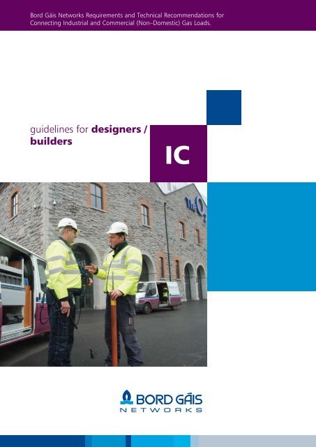
<strong>Bord</strong> Gáis <strong>Networks</strong> Requirements and Technical Recommendations <strong>for</strong><br />
Connecting Industrial and Commercial (Non–Domestic) Gas Loads.<br />
<strong>guidelines</strong> <strong>for</strong> <strong>designers</strong> /<br />
<strong>builders</strong><br />
<strong>IC</strong>
Definition<br />
In the context of this guidance document, an industrial / commercial connection constitutes the<br />
addition of any non-domestic gas load to the natural gas distribution network.<br />
Table of Contents<br />
section 1:<br />
introduction<br />
• Table of Contents 2<br />
• Introduction 4<br />
• Scope / Irish Standards 5<br />
section 2:<br />
The benefits of natural gas<br />
• Why Natural Gas? 6<br />
• Electricity Generation CHP 7<br />
• Space Heating 8<br />
• Water Heating 9<br />
• Catering 9<br />
• Cooling 9<br />
Section 3:<br />
Organising a natural gas connection 10<br />
Section 4:<br />
Site work <strong>guidelines</strong> 12<br />
• Gas Main Guidelines 13<br />
• Site Ground-Work Guidelines 13<br />
• Gas Services Requirements 14<br />
Section 5:<br />
Meter types & specifications<br />
• Gas Load Categories 15<br />
• Specifications of Commercial and Industrial<br />
• Meter Types 16<br />
• On-Site Fabricated Meter Assemblies 17<br />
• Meter Modules 18<br />
• Skid Units 19<br />
• Base Requirements <strong>for</strong> Skid Units 21<br />
• Guidelines <strong>for</strong> Positioning Pressure<br />
• Reduction and Meter Installations 22<br />
• Steel Cage Protection 24<br />
• Purpose Built Meter Compartments 25<br />
• Locating Meters inside the Building 27<br />
• Meters Positioned in open Basement Areas 28<br />
2
Section 6:<br />
Installation pipework downstream of the meter<br />
• Gas Supply Pipework 29<br />
• Service Shafts 34<br />
• Installation Pipework 36<br />
• Appliance Connections 37<br />
• Means of Isolation 37<br />
• Material Selection 38<br />
• Corrosion Protection 38<br />
• Jointing 39<br />
• Pipework Support 40<br />
• Pipes in Voids 40<br />
• Sleeving 41<br />
• Pipe Sizing 42<br />
• Conversion Tables 44<br />
• Safety Devices 45<br />
• Design <strong>for</strong> Protection in Case of Fire 45<br />
• Identification of Pipework 46<br />
• Equipotential Bonding 46<br />
• Marking of Meters & Supply Pipework 46<br />
Section 7:<br />
Non-domestic premise certification<br />
• The Non-Domestic Certificate 47<br />
• Steps to Getting Meter Fitted 48<br />
• Completing the Declaration of Con<strong>for</strong>mance 48<br />
• Testing of Pipework 50<br />
• Strength and Soundness Testing 51<br />
• Flue Testing 52<br />
• Ventilation 52<br />
• Project Manager/Gas Installer Responsibility 53<br />
• Operator Responsibility 53<br />
Section 8:<br />
Appendix:<br />
• Gas Market Deregulation Terminology 54<br />
• Gas Load Terminology 55<br />
• Technical Terminology 56<br />
• Connections Form (Sheet 1 & 2) 61<br />
• Applicable Standards <strong>for</strong> Industrial/Commercial<br />
• Installations 64<br />
3
Section 1: Introduction<br />
Introduction: from shore to door<br />
Natural gas is found in large basins underneath the<br />
earth’s surface. Once brought from underground,<br />
the natural gas is treated to remove impurities like<br />
water, sand, and other compounds. After this cleaning<br />
process, a trace of a proprietary chemical is added to<br />
give the natural gas its identifiable odour be<strong>for</strong>e it is<br />
transmitted through a network of pipelines to its point<br />
of use.<br />
Since its establishment, <strong>Bord</strong> Gáis has developed a<br />
combined Transmission and Distribution pipeline<br />
network of 11,318km (year end 2005). The system is<br />
linked to UK and Continental gas markets through two<br />
subsea interconnector pipelines. Natural gas is now<br />
available in over 100 population centres within 19<br />
counties throughout the country with over 540,000<br />
gas users in Ireland.<br />
Businesses in Ireland have increasingly adopted natural gas as the preferred fuel <strong>for</strong>:<br />
Steam Generation<br />
typical applications include<br />
industrial processes and electricity<br />
generation.<br />
Combined Heat and Power (CHP)<br />
typical applications include hospitals,<br />
large hotels and leisure centres.<br />
Heating, Hot Water and Cooking<br />
typical applications include hospitals,<br />
shopping centres, factory workshops,<br />
offices, restaurants and public houses.<br />
If you OWN or MANAGE a business and you are considering a connection to the natural gas<br />
network, then this booklet will be of assistance to you.<br />
4
Scope / Irish Standards:<br />
This document has been prepared <strong>for</strong> the prospective<br />
gas customer, the construction industry professional<br />
and the mechanical contractor who wish to connect to<br />
the natural gas network.<br />
This booklet is a guidance document <strong>for</strong> natural<br />
gas distribution systems at pressures less than 5bar.<br />
Gas mains, services and meters transporting gas at<br />
pressures greater that 100mbar are not permitted<br />
inside the building line 1 of occupied properties.<br />
Consult <strong>Bord</strong> Gáis <strong>Networks</strong> <strong>for</strong> site specific<br />
clarification.<br />
In<strong>for</strong>mation contained within this document includes<br />
gas mains and service requirements, technical guidance<br />
relating to gas meters <strong>for</strong> a range of gas loads and<br />
installation requirements downstream of the meter.<br />
This document contains practical guidance and should<br />
not be a substitute <strong>for</strong> the current Irish Gas Standards,<br />
the Technical Guidance Documents (Building<br />
Regulations) or the Local Government (Multi-Storey<br />
Buildings) Act 1988.<br />
The requirement <strong>for</strong> the safe and efficient supply of<br />
piped natural gas to industrial/commercial premises (at<br />
meter outlet pressures less than 5bar) are contained<br />
in the current edition of I.S.820, “Non-Domestic Gas<br />
Installations”.<br />
The requirements <strong>for</strong> the installation of domestic type<br />
appliances in non-domestic buildings are set out in I.S.<br />
813, “Domestic Gas Installations”. The requirements<br />
<strong>for</strong> the pipework supplying these appliances is included<br />
in I.S. 820 “Non-Domestic Gas Installations”.<br />
The requirements relating to the installation or<br />
maintenance of industrial process equipment, be it<br />
either an appliance or a piping system, is not included<br />
in this booklet.<br />
For guidance on industrial installations with a<br />
maximum operating pressure greater 0.5bar (500mbar)<br />
or installation requiring a supply pressure exceeding 5<br />
bar consult I.S./EN 15001-2.<br />
In the event of any conflict between this document and<br />
the relevant Irish Standards, the current edition of the<br />
Irish Standard should prevail.<br />
All values <strong>for</strong> length are in millimetres unless otherwise<br />
stated.<br />
1, 2, 3 Refer to Section 8:<br />
Appendix – Terminology.<br />
As stated in Irish Standard I.S.820, only competent<br />
persons 2 are permitted to design, construct and<br />
commission gas installation pipework. The standard<br />
also states that competent personnel should only<br />
commission gas consuming equipment and appliances.<br />
Competent persons engaged in the design of gas<br />
installations and in gas installation work should comply<br />
with the current Building Regulations and the Local<br />
Government (Multi-Storey Buildings) Act 1988.<br />
The work and responsibility of the installation designer<br />
and mechanical contractor begins at the point<br />
of delivery 3 and continues up to and including all<br />
installation pipework and gas consuming equipment.<br />
5
Section 2: The benefits of natural gas<br />
Why natural gas?<br />
Since the 1980’s more and more energy users have<br />
adopted natural gas as their primary source of fuel <strong>for</strong><br />
heating, cooking and processing. Currently there are in<br />
excess of 540,000 customers connected to the natural<br />
gas network in Ireland.<br />
There are several reasons why the change to natural<br />
gas has taken place:<br />
• Optimising use of valuable space – with natural<br />
gas there is no need <strong>for</strong> an on site tank, external<br />
boiler house or excessively large installations<br />
consuming premium landscape, commercial or<br />
parking space.<br />
With all of the benefits above there is no doubt that<br />
when combined with modern equipment a natural<br />
gas connection can reduce the running costs of your<br />
property.<br />
There are many applications of natural gas and a<br />
range of appliances available to complement each<br />
application. The following pages provide examples of<br />
natural gas in use. For more in<strong>for</strong>mation and details<br />
on particular appliances please contact a natural gas<br />
appliance and equipment supplier.<br />
• Compact reliable appliances – due to the clean<br />
combustion of gas, often the appliances and<br />
equipment are smaller than <strong>for</strong> alternative fuels.<br />
This cleaner combustion process also means<br />
natural gas appliances and equipment are more<br />
reliable and often easier to maintain. Space usage<br />
within the building is thus optimised and costs<br />
reduced with high fuel efficient equipment.<br />
• Natural gas is very versatile and has many uses<br />
– from cooking to heating to generating a site’s<br />
electrical requirements through Combined Heat<br />
and Power (CHP), see page 7 <strong>for</strong> further details.<br />
• There are fewer carbon emissions with natural<br />
gas than with other fuels. Gas is cleaner<br />
than alternative fossil fuels as it<br />
produces less harmful pollutants during<br />
combustion, hence making it a more<br />
environmentally friendly fuel and suited to direct<br />
firing applications.<br />
• Natural gas is piped directly from a national and<br />
European network and is always ‘on-tap’. You<br />
only pay <strong>for</strong> natural gas when you use it, not in<br />
advance. There is no need to worry about on site<br />
storage, circulatory or conditioning systems.<br />
• Gas remains the most cost effective fuel on the<br />
market. See the Sustainable Energy Ireland’s<br />
website at www.sei.ie <strong>for</strong> the most up-to-date<br />
fuel price comparisons. The price of natural<br />
gas is regulated by the Commission <strong>for</strong> Energy<br />
Regulation (CER).<br />
6
Large Processing Loads and Large Electricity<br />
Generation Facilities:<br />
Very large natural gas consuming processing<br />
plants require a connection directly from high<br />
pressure transmission pipelines. <strong>Bord</strong> Gáis <strong>Networks</strong><br />
transmission pipelines provide natural gas to<br />
numerous facilities in the Republic of Ireland, as well<br />
as an electricity generating station in Northern Ireland<br />
and on the Isle of Man.<br />
The <strong>Bord</strong> Gáis Network transmission and distribution<br />
network can be viewed on the internet at www.<br />
bordgais.ie.<br />
The requirements relating to the installation<br />
or maintenance of industrial process<br />
equipment, be it either an appliance<br />
or a piping system, are not included in<br />
this booklet. For guidance on industrial<br />
installations with maximum operating<br />
pressure greater than 0.5bar (500mbar) or<br />
any installation requiring a supply pressure<br />
exceeding 5bar. Reference can be made to<br />
I.S./EN 15001-2.<br />
Combined heat and power (CHP):<br />
CHP uses gas to provide both heat and electrical<br />
power. The CHP unit burns gas to power a generator<br />
which in turn creates electricity. This electricity is then<br />
fed into the main fuse board <strong>for</strong> the site, reducing the<br />
electricity demand from the national grid. The result is<br />
lower electricity costs <strong>for</strong> the end user. The heat from<br />
gas combustion is used to heat water in the usual way<br />
<strong>for</strong> the heating system. This process results in very high<br />
efficiencies and an overall fuel cost reduction <strong>for</strong> the<br />
property.<br />
An added advantage is that as a site is generating part<br />
or all of its power, if there is a failure on the electricity<br />
grid, power will still be available to maintain essential<br />
operations. Larger CHP users can sell excess electricity<br />
back to their electricity supplier and so reduce their<br />
electricity bills even further.<br />
CHP has become an innovative solution <strong>for</strong> hotels<br />
in Ireland, in particular large hotels that have leisure<br />
facilities and swimming pools. As more towns in<br />
Ireland are connected to the natural gas network and<br />
technology has become more advanced, it is now<br />
possible <strong>for</strong> small CHP units to become a more viable<br />
option <strong>for</strong> a greater range of applications.<br />
Figure 1:<br />
The operating principles of CHP installation<br />
10% to 20%<br />
Waste<br />
Electricity, Heat and Hot Water<br />
80% to 90% efficiency<br />
Natural Gas<br />
Meter<br />
C.H.P.<br />
Factory,<br />
Hospital, Hotel<br />
or Leisure<br />
Centre<br />
100% Energy Input<br />
Figure 2:<br />
CHP unit<br />
7
Space heating:<br />
There are several ways natural gas can be adopted to provide the heating of premises. Below<br />
are just some of the options available.<br />
Warm Air Heaters<br />
Warm air heaters are available in multiple<br />
<strong>for</strong>mats such as free-standing, wall or<br />
ceiling mounted, all of which have different<br />
heat output ranges. The heaters are a tried<br />
and tested method of cost effective heating.<br />
They can <strong>for</strong>m part of warm air curtains<br />
above doors and loading bays.<br />
Radiant Heaters<br />
Gas fired radiant heaters have particular<br />
useful applications within large open areas.<br />
These units only direct heat to a desired<br />
area. There are two types of gas fired<br />
radiant heaters, radiant plaques or radiant<br />
tubes. Both utilise a radiant surface which<br />
directs heat to the desired area.<br />
Central Heating Boilers<br />
Central heating boilers are available in<br />
a wide array of sizes and heat outputs,<br />
meeting the needs of domestic and<br />
commercial customers. Condensing warm<br />
air heaters are also available which function<br />
in a similar fashion and can operate at<br />
efficiencies in excess of 95%.<br />
Balanced-Flue Convector Heaters<br />
These units are small convenient heaters <strong>for</strong><br />
smaller buildings and premises requiring<br />
intermittent heating, such as offices and<br />
small shops. These are local heaters which<br />
combust gas, releasing heat to the desired<br />
area and release products of combustion to<br />
atmosphere via their own flue.<br />
Figure 4:<br />
Decorative Fuel Effect Fire<br />
Figure 3:<br />
Small Commercial (Domestic Type)<br />
Central Heating Boiler<br />
Figure 5:<br />
Warm Air Heater<br />
8
Water heating:<br />
Central Heating Boilers<br />
The standard domestic central heating boiler or<br />
multiples interlinked provide both the heating and hot<br />
water requirement. In certain instances, a separate<br />
smaller boiler with a calorifier can be more efficient,<br />
while gas fired appliances which heat the water<br />
directly are even more efficient.<br />
Instantaneous Water Heaters<br />
Instantaneous water heaters are ideal <strong>for</strong> local small<br />
quantities of hot water. There are a range of appliances<br />
available which can heat several litres of water per<br />
minute.<br />
Storage Water Heaters<br />
These gas heaters have a high recovery rate which<br />
can reduce the need <strong>for</strong> large on site storage. There<br />
is a broad range of models available and these are<br />
particularly suited to large quantities of hot water,<br />
stored either centrally or local to usage.<br />
Figure 6:<br />
Storage Water Heater<br />
Catering:<br />
Natural gas is the fuel of choice <strong>for</strong> professional<br />
caterers; its flexibility and instant response make it the<br />
fuel that is in greatest demand <strong>for</strong> chefs today. There<br />
are a wide range of gas cooking appliances available,<br />
from small restaurants to large hotel kitchens.<br />
Equipment such as convection ovens, deep fat fryers,<br />
griddles, combination ovens and gas ring hobs give<br />
the full range of applications. Gas heated dishwashing<br />
machines are available <strong>for</strong> cleaning of cutlery,<br />
glassware and crockery. Appliances specifically <strong>for</strong> the<br />
fast food industry, such as gas heated conveyor boilers<br />
and fryers are also available.<br />
Figure 8:<br />
Kitchen and Catering Equipment<br />
Cooling:<br />
Gas fired absorption chillers have a very low level of<br />
noise and vibration. The majority of units are available<br />
as chillers/heaters which provide cooling and heating<br />
operations from the one unit. This dual functionality<br />
provides efficient and there<strong>for</strong>e economic operation.<br />
Figure 7:<br />
Central Boiler<br />
9
Section 3: ORGANISING A NATURAL GAS CONNECTION<br />
In<strong>for</strong>mation required <strong>for</strong> a gas connection:<br />
To process your application <strong>for</strong> a gas<br />
connection it is essential that the following<br />
in<strong>for</strong>mation is provided to <strong>Bord</strong> Gáis<br />
<strong>Networks</strong>. The listing below highlights the<br />
minimum required to design the connection<br />
and accurately evaluate the capital<br />
contribution required.<br />
a. Connections Form 4<br />
b. Site Location Drawing (to be sent to plans@bge.ie)<br />
c. Proposed Meter Locations shown on Drawing (to be sent to plans@bge.ie)<br />
d. Estimated Annual Consumption (EAC) 5 (or, note point y below)<br />
e. Maximum Hourly Quantity (MHQ) of Gas Required 6<br />
f. Pressure Required (Meter outlet pressure normally provided at 21mbar)<br />
g. Details of Possible Future Loads<br />
x. Minimum Hourly Quantity (average)<br />
(Only required if Category 3 Connection, see table on page 15)<br />
y. Historic Fuel Bills<br />
(Only required when premise is changing over from an alternate fuel)<br />
z. Gas Point Registration Number, GPRN 7<br />
(Only required if alteration to the existing meter or service required)<br />
Table 1:<br />
The in<strong>for</strong>mation required to organise gas connection.<br />
Natural gas is delivered through a pipework<br />
distribution system and supply pressures vary<br />
in accordance with the design and operation<br />
of the system local to the premise being<br />
connected. To confirm availability of necessary<br />
gas volume and pressure contact Network<br />
Connections at 1850 427 747.<br />
The route <strong>for</strong> supplying natural gas to a<br />
building and final location of the point of<br />
delivery 8 (normally the meter) is decided by<br />
<strong>Bord</strong> Gáis <strong>Networks</strong> following consultation<br />
with the customer or the customer’s<br />
nominated representative.<br />
The gas main, service, pressure reduction and<br />
primary meter(s) remain the property of <strong>Bord</strong><br />
Gáis <strong>Networks</strong>.<br />
Installations are designed to deliver 21mbar,<br />
unless otherwise requested. <strong>Bord</strong> Gáis<br />
<strong>Networks</strong> do not supply gas at pressures<br />
greater than those available from the local<br />
network 9 .<br />
In accordance with the current CER<br />
Connections Policy, a design fee is applicable<br />
<strong>for</strong> large connection applications with an<br />
Estimated Annual Consumption (EAC)<br />
above a published value. Consult the <strong>Bord</strong><br />
Gáis <strong>Networks</strong> website <strong>for</strong> further details,<br />
www.bordgais.ie.<br />
Refer to Appendix <strong>for</strong> Connections Form and<br />
Page 11 <strong>for</strong> the schedule to Coordinate a<br />
Natural Gas Connection.<br />
4<br />
A Connections Form should be<br />
completed <strong>for</strong> all connection requests.<br />
A sample <strong>for</strong>m is provided in Section 8<br />
of this booklet. An electronic version is<br />
available on request from connect@<br />
bge.ie and on the internet at www.<br />
bordgais.ie<br />
5<br />
, 6 , 7 , 8 , 9 Refer to Section 8: Appendix –<br />
Terminology.<br />
10
Project Number Assigned:<br />
Schedule <strong>for</strong> Co-ordinating Business Connections<br />
DESIGN PHASE - <strong>Bord</strong> Gáis <strong>Networks</strong> DATE:<br />
1. Customer/Customer’s Representative contacts <strong>Bord</strong> Gáis <strong>Networks</strong> on 1850 427 747 to acquire<br />
details of existing gas network in area.<br />
2. Customer/Customer’s Representative contacts <strong>Bord</strong> Gáis Network Connections on<br />
1850 427 737 requesting a Connections Form. This should be completed and returned with a<br />
site location map and site layout drawings to plans@bge.ie.<br />
. . . / . . . / . . .<br />
. . . / . . . / . . .<br />
3. <strong>Bord</strong> Gáis <strong>Networks</strong> will arrange a meeting to agree the network route and positioning of gas<br />
meters and ancillary equipment prior to proceeding with project design and estimation. Private<br />
way leave agreements to be sought by Customer where applicable.<br />
. . . / . . . / . . .<br />
4. When the above details are finalised, <strong>Bord</strong> Gáis <strong>Networks</strong> design the gas connection and<br />
provide written quotation, proposed gas network drawings and contract documents to<br />
the Customer.<br />
5. Customer returns signed contract with connection fee.<br />
6. <strong>Bord</strong> Gáis <strong>Networks</strong> seek way-leave permissions from local authorities.<br />
CONSTRUCTION PHASE - <strong>Bord</strong> Gáis <strong>Networks</strong><br />
. . . / . . . / . . .<br />
. . . / . . . / . . .<br />
. . . / . . . / . . .<br />
1. Customer’s project manager contacts <strong>Bord</strong> Gáis <strong>Networks</strong> on 1850 427 747 to acquire details<br />
of existing gas network within scope of site and safety labels <strong>for</strong> site.<br />
2. Customer’s project manager liaises with <strong>Bord</strong> Gáis <strong>Networks</strong> pipe laying contractor to<br />
co-ordinate site works.<br />
FINAL METER CONNECTION - Natural Gas Supplier<br />
1. Consumer contacts a natural gas supplier and agrees terms of supply (Referencing their<br />
GPRN).<br />
. . . / . . . / . . .<br />
. . . / . . . / . . .<br />
. . . / . . . / . . .<br />
2. Mechanical Contractor / Heating Installer prepares installation <strong>for</strong> meter fit, completes the “BGN<br />
Office Copy” of the Non-Domestic Certificate of Con<strong>for</strong>mance and faxes it to<br />
1850 211 447.<br />
3. Consumer requests fitting of meter through their gas supplier (Not <strong>Bord</strong> Gáis <strong>Networks</strong>).<br />
. . . / . . . / . . .<br />
. . . / . . . / . . .<br />
4. <strong>Bord</strong> Gáis <strong>Networks</strong> fit the meter after request from the consumers’ nominated natural gas<br />
supplier (if the Certificate of Con<strong>for</strong>mance is completed and available on site).<br />
. . . / . . . / . . .<br />
Individual GPRN Number(s) Assigned to each Gas Meter to be Fitted:<br />
11
Section 4: site work requirements<br />
Site work <strong>guidelines</strong><br />
Cabinet containing gas<br />
meter and<br />
pressure<br />
regulator<br />
Pavement<br />
Carriageway<br />
Gas<br />
Distribution<br />
Mains<br />
GAS<br />
Supply<br />
Pipework<br />
Gas<br />
Service<br />
External<br />
Isolation<br />
Valve<br />
I.S 820<br />
I.S 265<br />
Service<br />
Top Tee<br />
200mm<br />
Figure 9:<br />
The Gas Mains Service and Meter.<br />
I.S 329<br />
Note:<br />
• Gas mains, services and meters transporting gas at<br />
pressures greater than 100mbar are not permitted<br />
inside the building line of occupied buildings<br />
190mm<br />
The external isolation valve<br />
and access cover should<br />
remain accessible at all<br />
times.<br />
• PE piping is not permitted inside the building<br />
• The service should travel as near perpendicular to the<br />
gas main as possible<br />
12
Gas mains (i.S. 329)<br />
All gas mains should be installed by <strong>Bord</strong> Gáis<br />
<strong>Networks</strong> or a <strong>Bord</strong> Gáis <strong>Networks</strong> appointed<br />
contractor. On new–build projects, the builder<br />
normally provides a pre-excavated trench.<br />
All trenches constructed <strong>for</strong> the purpose of<br />
accommodating gas main should allow <strong>for</strong> a<br />
minimum cover of 750mm. Gas mains should not<br />
be laid with cover greater than 1200mm, unless<br />
specified by <strong>Bord</strong> Gáis <strong>Networks</strong>.<br />
with other utilities / services or drainage / sewage<br />
systems. A distance of 300mm should be provided<br />
when a gas main is placed adjacent to an<br />
inspection chamber (note Figure 10 below).<br />
Gas<br />
Main<br />
Water<br />
Main<br />
The total trench width should amount to outside<br />
diameter of gas pipe, plus 300mm.<br />
Sand or pea gravel, 150mm minimum should<br />
surround the gas main. The trench should be<br />
reinstated as soon as practicable after the main is<br />
laid so to reduce the possibility of damage on site.<br />
The typical layout of a gas main in a footpath is<br />
shown in Figure 11 below.<br />
Inspection<br />
Chamber<br />
(Manhole)<br />
300mm<br />
min<br />
3<br />
Site ground-work<br />
Guidelines<br />
Under no circumstances may the<br />
gas main be included in an inspection chamber<br />
Figure 10:<br />
Permissible proximity of gas mains to inspection chambers<br />
Note:<br />
Other utilities/ducts should not be laid on top of gas<br />
main/service<br />
Boundary Wall<br />
750mm minimum cover required beneath roads<br />
650mm minimum cover required beneath<br />
footpaths and landscape areas<br />
300<br />
600mm minimum distance between high<br />
voltage mains & gas mains<br />
Granular Material<br />
Elec/Telecom<br />
Ducts<br />
Marker tape<br />
250mm<br />
150mm Compacted<br />
Sand Surround<br />
Section Drawing<br />
Gas main<br />
300min<br />
Water Main<br />
Figure 11: Trench requirements <strong>for</strong> gas mains.<br />
13
GAS SERV<strong>IC</strong>ES (I.S. 265)<br />
All gas services should be installed by <strong>Bord</strong> Gáis<br />
<strong>Networks</strong> or a <strong>Bord</strong> Gáis <strong>Networks</strong> appointed<br />
contractor in a pre-excavated trench, normally<br />
provided by the builder. Any extra site works required<br />
by <strong>Bord</strong> Gáis <strong>Networks</strong> will incur additional charges.<br />
• All new industrial and commercial services should<br />
incorporate an underground service isolation<br />
valve which should remain accessible to<br />
<strong>Bord</strong> Gáis <strong>Networks</strong> and the Emergency Services.<br />
The gas service should be laid in a straight line to the<br />
meter location, as near perpendicular to the gas main<br />
as practicable.<br />
• Mains, services and meters transporting gas at<br />
pressures greater than 100mbar may not be<br />
positioned within the building line of occupied<br />
premises (as defined by I.S.329 / I.S.265).<br />
• For more detailed in<strong>for</strong>mation, always refer to<br />
the <strong>Bord</strong> Gáis <strong>Networks</strong> drawings specific to the<br />
project.<br />
Service Requirements:<br />
1. The trench <strong>for</strong> the gas service to each meter<br />
location should be excavated to a sufficient<br />
depth to allow a minimum cover of 600mm.<br />
In the case where the service supplies a single<br />
G4 meter box (per page 17) with a single meter<br />
contained within, 600mm minimum cover is<br />
required up to 1.5 metres from the meter box.<br />
Within the remaining 1.5 metre distance, cover<br />
may reduce to a minimum of 375mm to the base<br />
of the GRP sleeve (note Figure 9 on page 12).<br />
5. Marker tape (provided by the <strong>Bord</strong> Gáis <strong>Networks</strong><br />
contractor) should be placed over all gas mains,<br />
services and ducting intended <strong>for</strong> gas distribution<br />
pipe insertion at a later date.<br />
6. <strong>Bord</strong> Gáis <strong>Networks</strong> should be consulted if it is<br />
proposed to place the service in a sleeve or duct.<br />
2. All gas trenches should be excavated to the width<br />
of the outside diameter of pipe, plus 300mm.<br />
3. Sand or pea gravel, 150mm minimum should<br />
surround the gas service.<br />
4. Where the necessity to cross or run in close<br />
proximity to any other utility occurs, a minimum<br />
clearance of 300mm is required.<br />
14
Meter types & specifications<br />
Industrial and Commercial customer gas meters can be<br />
classified into the following three categories:<br />
Peak gas load (gl) categories<br />
CATEGORY 1: Generally On-Site Fabrications<br />
Peak gas load less than 165 kWh<br />
(GL < 563,003 BTU’s)<br />
G4, G10 – METERS:<br />
(Refer to page 17 <strong>for</strong> further details)<br />
Step 1:<br />
Meters fitted on-site by <strong>Bord</strong> Gáis <strong>Networks</strong> meter fitter, after<br />
receipt of Declaration of Con<strong>for</strong>mance, refer to Section 7.<br />
CATEGORY 2: Generally Meter Modules<br />
Peak gas load greater than 165 kWh and less than 1,035 kWh<br />
(563,003 BTU’s < GL < 3,531,566 BTU’s)<br />
G16, G25, G40, G65 - METER MODULES:<br />
(Refer to page 18 <strong>for</strong> further details)<br />
Step 1:<br />
Step 2:<br />
Meter modules manufactured off-site<br />
Module fitted and meter commissioned on site after<br />
receipt of Declaration of Con<strong>for</strong>mance, refer to Section 7.<br />
CATEGORY 3: Generally Skid Units<br />
Peak gas load greater than 1,035 kWh<br />
(GL > 3,531,566 BTU’s)<br />
G100, G160, G250, G400, G650, SP1, SP2 - SKID UNITS:<br />
Step 1:<br />
Step 2:<br />
Step 3:<br />
Step 4:<br />
Step 5:<br />
Pressure Reduction Skid manufactured off-site (refer to pages<br />
19 & 20)<br />
Concrete Base placed in <strong>Bord</strong> Gáis <strong>Networks</strong> agreed position<br />
by client or builder (refer to page 21)<br />
Pressure Reduction Skid placed on concrete base<br />
Protection is placed around the skid installation<br />
Meter fitted and commissioned on-site after receipt of<br />
Declaration of Con<strong>for</strong>mance, refer to Section 7.<br />
Table 3: The Range of Gas Meters available<br />
The meter will not be fitted unless any required meter protection has been installed.<br />
15
Meter Maximum On-Site Fab, Module Compartment Base Fitting needed<br />
Type: Flow Rate or Skid Delivery: Type / Size: Required? <strong>for</strong> outlet pipe<br />
m 3 /h (kWh)<br />
G4 6 m 3 /h On-Site Fabrication Meter Box No<br />
Meter On-Site Fabrication Manifold No 3<br />
/ 4<br />
inch<br />
(63 kWh) Module + Fitter Six Meter No Copper<br />
Fabrication<br />
Cabinet<br />
G10 16 m 3 /h Module (LP) 1020h x 850w x 260d No 1.5 “ BSTP<br />
Fitter Fabrication (LP) 600h x 600w x 200d No 1.5 “ BSTP<br />
(166 kWh) Module (MP) 1020h x 850w x 260d No 1.5 “ BSTP<br />
Fitter Fabrication (MP) 600h x 600w x 200d No 1.5 “ BSTP<br />
G16 20 m 3 /h Module (LP) 580h x 850 w x 280d No 1.5 “ BSTP<br />
(210 kWh) Module (MP) 1000h x 450w x 250d No 1.5 “ BSTP<br />
G25 32 m 3 /h Module (LP) 1020h x 680w x 280d No 1.5 “ BSTP<br />
Module (MP) 1020h x 680w x 260d No 1.5 “ BSTP<br />
(340 kWh)<br />
G40 52 m 3 /h Module (LP) 1300h x 750w x 330d No 2 “ BSTP<br />
Skid Unit (LP) 2000h x 1350w x 800d Yes 50mm PN16 flange<br />
(550 kWh) Module (MP) 1300h x 650w x 350d No 2 “ BSTP<br />
Skid Unit (MP) 2000h x 1350w x 800d Yes 50mm PN16 flange<br />
G65 80 m 3 /h Module (LP) 1100h x 980w x 350d No 2 “ BSTP<br />
Skid Unit (LP) 2000h x 1350w x 800d Yes 50mm PN16 flange<br />
(840 kWh) Module (MP) 1300h x 750w x 350d No 2 “ BSTP<br />
Skid Unit (MP) 2000h x 1350w x 800d Yes 50mm PN16 flange<br />
G100 128 m 3 /h Skid Unit (LP) 2500h x 1800w x 800d Yes 100mm PN16<br />
Skid Unit (MP) 2000h x 1350w x 800d Yes flange<br />
(1,350 kWh)<br />
G160 200 m 3 /h Skid Unit (LP) 2500h x 1800w x 800d Yes 100mm PN16<br />
Skid Unit (MP) 2000h x 1350w x 800d Yes flange<br />
(2,100 kWh)<br />
G250* 320 m 3 /h Skid Unit (LP) 2500h x 1800w x 800d Yes 100mm PN16<br />
Skid Unit (MP) 2500h x 1800w x 800d Yes flange<br />
(3,400kWh)<br />
Yes<br />
G400* 520 m 3 /h Skid Unit (LP) 2500h x 3000w x 3000d Yes 100mm PN16<br />
Skid Unit (MP)<br />
flange<br />
(5,500 kWh)<br />
G650* 800 m 3 /h Skid Unit (MP) 2500h x 3500w x 3000d Yes 150mm PN16<br />
(8,500 kWh) flange<br />
SP1* 1,920 m 3 /h Skid Unit (MP) 2500h x 3500w x 3500d Yes 150mm PN16<br />
(21,000 kWh) flange<br />
SP2* 3,200 m 3 /h Skid Unit (MP) 2500h x 5000w x 4000d Yes 150mm PN16<br />
(34,000 kWh) flange<br />
Table 4: Full range of meters indicating Type, Maximum Flow<br />
Rate, Minimum Compartment Sizes and Outlet Supply fitting<br />
required.<br />
Notes:<br />
Final specification of meters by <strong>Bord</strong> Gáis <strong>Networks</strong><br />
Gas Main, services and meters transporting gas at<br />
pressures greater than 100 mbar are not permitted<br />
within the building line of occupied premises<br />
Under no circumstances is PE piping permitted inside<br />
the building<br />
All flange pipe connections should include a gasket<br />
* Meter Bypass Available, subject to evaluation. Refer<br />
to terminology <strong>for</strong> further details.<br />
Refer to pages 17 to 20 <strong>for</strong> further details. Green text<br />
indicates low pressure and blue text indicates medium<br />
pressure.<br />
16
0n-site fabricated meter assemblies<br />
(pressure reduction & metering):<br />
The Surface Mounted Meter Box:<br />
Facilitates a G4 (LP/MP) meter<br />
Figure 12: The Surface-Mounted Meter Box<br />
The Recessed Meter Box:<br />
Facilitates a G4 (LP/MP), G16 (LP/MP) meter<br />
Figure 13: The Recessed Meter Box<br />
The Six Meter Cabinet:<br />
Cabinet Dimensions: 1160h x 750w x 300d<br />
Note: The meter box should not be punctured<br />
when recessed into cavity walls or voids.<br />
The Steel Meter Manifold:<br />
Facilitates G4’s (LP/MP), G10’s (LP/MP) or connection<br />
of Meter Modules (see page 16 <strong>for</strong> dimensions)<br />
Outlet Pipework<br />
Isolation valve placed in an<br />
accessible position.<br />
Figure 14: The Six-Meter Cabinet.<br />
Further in<strong>for</strong>mation on the G4 meter, meter cabinet and manifold options refer to in Booklet 1, pages 5 – 12 and<br />
Booklet 3, pages 3 – 8.<br />
Both the Steel Meter Manifold and Six Meter Cabinet are manufactured off-site to facilitate multiple meter<br />
connections.<br />
Each of the above installation options should be placed a minimum of 300 mm above finished ground level.<br />
17<br />
Figure 15: The Meter Manifold within Purpose-Built<br />
Compartment
Pre-fabricated meter modules (pressure<br />
reduction & metering):<br />
Meter modules are surface mounted and arrive on site<br />
assembled and pre-locked.<br />
When delivered they require a gas service connection<br />
carried out by <strong>Bord</strong> Gáis <strong>Networks</strong> or a <strong>Bord</strong> Gáis<br />
<strong>Networks</strong> nominated contractor. The supply pipework<br />
connection is carried out by the client’s nominated gas<br />
installer.<br />
Only after these connections are complete can the<br />
module be unlocked and the meter commissioned. The<br />
clients nominated gas installer should be on-site <strong>for</strong><br />
co-ordination of commissioning and verification of the<br />
Declaration of Con<strong>for</strong>mance 10 .<br />
Typical Applications:<br />
Small to medium sized commercial customers (note<br />
maximum kWh and maximum flow rates below).<br />
Figure 16: A G25 Meter Module connecting a<br />
complex of offices in Naas, Co. Kildare<br />
Meter Module Specifications<br />
Modules Outer dimensions Maximum flow rate Supply outlet<br />
of module (mm) (m 3 /h)/gas load (kWh) fittings<br />
G10 (LP) 520h x 700w x 210d 16 m 3 /h / 166 kWh 1.5” BSTP<br />
G10 (MP) 520h x 700w x 210d 16 m 3 /h / 166 kWh 1.5” BSTP<br />
G16 (LP) 580h x 700w x 230d 20 m 3 /h / 210 kWh 1.5” BSTP<br />
G16 (MP) 400h x 300w x 200d 20 m 3 /h / 210 kWh 1.5” BSTP<br />
G25 (LP) 520h x 532w x 230d 32 m 3 /h / 340 kWh 1.5” BSTP<br />
G25 (MP) 520h x 530w x 210d 32 m 3 /h / 340 kWh 1.5” BSTP<br />
G40 (LP) 800h x 600w x 280d 52 m 3 /h / 550 kWh 2” BSTP<br />
G40 (MP) 700h x 500w x 300d 52 m 3 /h / 550 kWh 2” BSTP<br />
G65 (LP) 630h x 830w x 300d 80 m 3 /h / 840 kWh 2” BSTP<br />
G65 (MP) 800h x 600w x 300d 80 m 3 /h / 840 kWh 2” BSTP<br />
Table 5: Technical details <strong>for</strong> Meter Modules.<br />
Low Pressure (LP) meter modules are connected to a<br />
gas distribution network of less than 100mbar. The<br />
standard module outlet pressure is set at 20mbar.<br />
Meter Module Positions<br />
Medium pressure (MP) meter modules are connected<br />
to the gas distribution network of pressure greater<br />
than 100mbar. Under no circumstances may the<br />
medium pressure steel or polyethylene service,<br />
including meter module, be positioned within the<br />
building line 12 of occupied premises. Each meter<br />
module should be placed a minimum of 500mm<br />
above finished ground level.<br />
10<br />
Refer to Section 7: Certification of Non-<br />
Domestic Gas Installations.<br />
11<br />
, 12 Refer to Section 8: Appendix – Terminology.<br />
18
Skid units (pressure reduction & metering):<br />
Figure 17 & Figure 18: A SP1 meter connecting a<br />
pharmaceutical plant in Athlone, Co Westmeath and a G65<br />
unit placed in a naturally ventilated basement 14 connecting a<br />
hotel in Sandy<strong>for</strong>d, Co. Dublin.<br />
Skid units are delivered to site assembled and prelocked.<br />
They are positioned and supported on a<br />
concrete base provided by the client / builder (refer<br />
to page 21 <strong>for</strong> further details). When delivered they<br />
require a gas service connection organised by <strong>Bord</strong><br />
Gáis <strong>Networks</strong> or a <strong>Bord</strong> Gáis <strong>Networks</strong> nominated<br />
contractor, and a supply pipework connection carried<br />
out by the client’s nominated gas installer.<br />
Only after these connections are complete and<br />
appropriate protection provided can the skid unit be<br />
unlocked, the meter fitted and the completed<br />
installation commissioned. The clients nominated<br />
gas installer should be on-site <strong>for</strong> coordination of<br />
commissioning and verification of the Declaration of<br />
Con<strong>for</strong>mance 13 .<br />
Typical Applications:<br />
Large commercial premises and industrial processing<br />
loads (note maximum kWh and maximum flow rates<br />
below).<br />
Skid Unit Specifications:<br />
Meter Space Maximum flow rate Supply outlet<br />
Required (m 3 /h) / maximum fittings<br />
Gas load (kWh)<br />
G40 (LP) 2000h x 1350w x 800d 52 m 3 /h / 550 kWh 2” BSTP<br />
G40 (MP) 2000h x 1350w x 800d 52 m 3 /h / 550 kWh 2” BSTP<br />
G65 (LP) 2000h x 1350w x 800d 80 m 3 /h / 840 kWh 2” BSTP<br />
G65 (MP) 2000h x 1350w x 800d 80 m 3 /h / 840 kWh 2” BSTP<br />
G100 (LP) 2500h x 1800w x 800d 128 m 3 /h / 1,350 kWh 100mm PN 16 flange<br />
G100 (MP) 2000h x 1350w x 800d 128 m 3 /h / 1,350 kWh 100mm PN 16 flange<br />
G160 (LP) 2500h x 1800w x 800d 200 m 3 /h / 2,100 kWh 100mm PN 16 flange<br />
G160 (MP) 2000h x 1350w x 800d 200 m 3 /h / 2,100 kWh 100mm PN 16 flange<br />
G250 (LP)* 2500h x 1800w x 800d 320 m 3 /h / 3,400 kWh 100mm PN 16 flange<br />
G250 (MP)* 2500h x 1800w x 800d 320 m 3 /h / 3,400 kWh 100mm PN 16 flange<br />
G400 (MP)* 2500h x 3260w x 2240d 520 m 3 /h / 5,500 kWh 100mm PN 16 flange<br />
G650 (MP)* 2500h x 4400w x 2500d 800 m 3 /h / 8,500 kWh 150mm PN 16 flange<br />
SP 1 (MP)* 2500h x 4000w x 3050d 1,920 m 3 /h / 21,000 kWh 150mm PN 16 flange<br />
SP 2 (MP)* 2500h x 4800w x 3150d 3,200 m 3 /h / 34,000 kWh 150mm PN 16 flange<br />
* Meter Bypass Available 15 , subject to <strong>Bord</strong> Gáis <strong>Networks</strong> evaluation.<br />
Table 6: Technical details <strong>for</strong> Skid Units<br />
19
Low Pressure (LP) skid units are connected to the gas<br />
distribution network of pressure less than 100mbar.<br />
The standard outlet pressure is set at 20mbar.<br />
Medium pressure (MP) skid units are connected to<br />
the gas distribution network of pressure greater than<br />
100mbar. Under no circumstances may a medium<br />
pressure steel or polyethylene service, with meter,<br />
be positioned within the building line of occupied<br />
premises.<br />
Protection in the <strong>for</strong>m of a palisade fence or cage<br />
is included into the connection cost by <strong>Bord</strong> Gáis<br />
<strong>Networks</strong> (Refer to page 24 <strong>for</strong> further details). The<br />
customer may provide the required protection only<br />
if the design has been pre-agreed with <strong>Bord</strong> Gáis<br />
<strong>Networks</strong>. Note: The Meter will remain locked until<br />
protection has been installed.<br />
Electronic Daily Metering is necessary on all<br />
connections with an estimated annual consumption<br />
(EAC) 16 greater that 5.55GWh (5,550,000 kWh).<br />
Electronic Daily Metering may be provided on skid<br />
units of lesser EAC’s after request from the client and<br />
evaluation by <strong>Bord</strong> Gáis <strong>Networks</strong>.<br />
If a twin stream skid is specified, the customer / builder<br />
is recommended to request specific compartment and<br />
concrete base details from <strong>Bord</strong> Gáis <strong>Networks</strong>.<br />
13<br />
Refer to Section 7: Certification of<br />
Non-Domestic Gas Installations.<br />
14<br />
Refer to Section 5, page 28:<br />
Meters located in Open Basement Areas.<br />
15<br />
, 16 Refer to Section 8: Appendix – Terminology.<br />
Building Energy Management Systems (BEMS) are<br />
computer systems which enable the system operator<br />
to monitor and control building services including<br />
heating, air conditioning and lighting. BEMS are also<br />
capable of automatically recording gas and electricity<br />
consumption via the relevant meters and the data<br />
obtained can be used, <strong>for</strong> example, to analyse energy<br />
usage trends and to record and <strong>for</strong>ecast annual energy<br />
consumptions.<br />
Through on-line monitoring of energy usage,<br />
customers can identify and report on energy<br />
consumption data which will help to identify costsaving<br />
opportunities and promote energy conservation<br />
between occupants and building managers.<br />
<strong>Bord</strong> Gáis <strong>Networks</strong> is committed to promoting energy<br />
efficiency and if requested we can provide a Low<br />
Frequency (LF) Pulse Output from a <strong>Bord</strong> Gáis <strong>Networks</strong><br />
meter. This device enables the BEMS to record the<br />
throughput of gas through the gas meter.<br />
20
Base requirements <strong>for</strong> skid units:<br />
C<br />
B<br />
A<br />
E<br />
D<br />
C<br />
C<br />
D<br />
E<br />
C<br />
Figure 19: Concrete Base Detail<br />
SKID<br />
DIMENSIONS<br />
A B C D E<br />
G40 LP 1,800 1,650 750 775 150<br />
G40 to G65 (MP) 1,800 1,650 750 790 150<br />
G65 (LP) 1,800 1,650 725 715 200<br />
G100 (MP) to G160 (MP) 1,800 1,650 725 700 200<br />
G100 to G160 (LP) 2,300 1,650 675 550 300<br />
G250 (LP) 2,300 1,650 675 560 300<br />
G250 (MP) 2,300 1,650 725 480 200<br />
G400 (MP) Axial Flow 5,000 3,000 1,400 1200 200<br />
G400 (MP) Direct Acting 5,000 3,000 1,400 1200 200<br />
G650 (MP) Axial Flow 5,000 3,000 1,350 1,225 300<br />
G650 (MP) Direct Acting 5,000 3,000 1,350 1,175 300<br />
SP1 (MP) Axial Flow 4,000 3,500 1,600 1,200 300<br />
SP1 (MP) Direct Acting 5,000 3,500 1,600 1,350 300<br />
SP2 (MP) Axial Flow 5,500 4,000 1,850 1,300 300<br />
SP2 (MP) Direct Acting 5,500 4,000 1,850 1,200 300<br />
Table 7: Dimensions <strong>for</strong> sizing the concrete Base<br />
All skid units require a base consisting of concrete (150mm thick) placed on a consolidated<br />
hardcore (150mm thick). The builder/customer is responsible <strong>for</strong> placing the base in the position<br />
as agreed with <strong>Bord</strong> Gáis <strong>Networks</strong>.<br />
If a twin stream skid is specified, request specific compartment and concrete base details from<br />
<strong>Bord</strong> Gáis <strong>Networks</strong>.<br />
Dimensions may change subject to site specific requirements and should be confirmed with <strong>Bord</strong><br />
<strong>Gais</strong> <strong>Networks</strong> at time of construction.<br />
21
Guidelines <strong>for</strong> positioning pressure reduction<br />
and metering installations:<br />
• <strong>Bord</strong> Gáis <strong>Networks</strong> provide and lay all gas<br />
mains and service pipework up to and including<br />
the point of delivery (normally including the<br />
meter).<br />
• Full access should be provided to the installation<br />
<strong>for</strong> <strong>Bord</strong> Gáis <strong>Networks</strong> authorised personnel at<br />
all times to facilitate construction of the meter<br />
installation and subsequent maintenance.<br />
• Service pipework provided by <strong>Bord</strong> Gáis<br />
<strong>Networks</strong> <strong>for</strong> meters or pressure reduction<br />
equipment should be positioned prior to<br />
pouring of floor slab.<br />
• The meter and/or pressure reduction equipment<br />
should be within the confines of the customer’s/<br />
developer’s property and as close as practicable<br />
to the premise being supplied.<br />
• All meter installations should be located in a welldrained<br />
area that is not liable to flooding. Design<br />
and/or location should protect the meter and its<br />
connections against the possibility of corrosion.<br />
The meter installation should not be located<br />
directly beneath a ventilation grill or in a position<br />
liable to allow ingress of water unless weather<br />
protected.<br />
• All meters and associated supply pipework should<br />
be earth bonded by the customer’s nominated<br />
electrical contractor in accordance with the current<br />
edition of the ETCI Regulations.<br />
• Meters should always be positioned in an area of<br />
natural ventilation.<br />
17<br />
Refer to Section 8: Appendix - Terminology<br />
• Care should be taken when locating the external<br />
isolation valve so it is freely accessible at all<br />
times, e.g. not in a parking area where vehicles<br />
may restrict access (Note page 12).<br />
• Planning permission should be obtained by<br />
the customer where necessary, i.e. <strong>for</strong> external<br />
structures designed to conceal or protect district<br />
regulator installations (DRI’s) 17 and gas meters.<br />
• Above ground gas services should only pass<br />
through naturally ventilated areas that are<br />
publicly accessible (i.e. providing access <strong>for</strong> <strong>Bord</strong><br />
Gáis <strong>Networks</strong> maintenance at all times).<br />
• Gas meter and ancillaries may not be placed in<br />
a space which may hinder escape in the event<br />
of an emergency.<br />
• Meters should not be located where they may<br />
be exposed to accidental damage. Adequate<br />
protection should be provided by the customer/<br />
builder against possible equipment damage<br />
or tamper. Installations in close proximity to a<br />
traffic area should be fitted with a suitable crash<br />
barrier.<br />
• Underground natural gas pipework should be a<br />
minimum of 300mm from electrical mains. Gas<br />
equipment should not be positioned beneath<br />
overhead electrical cables or trees (applicable to<br />
skid units only, note pages 19 and 20).<br />
22
Meters should not be located:<br />
• adjacent to medium voltage (MV) electricity<br />
substations (minimum direct communicating<br />
distance of 10 metres required)<br />
• in an area adjacent to L.P.G., or a flammable<br />
material storage area where paper, timber or<br />
chemicals are stored<br />
• in an area adjacent to ventilation ducting or an<br />
air conditioning intake system<br />
• where they may be exposed to extreme<br />
temperatures or ignition sources (e.g. switch<br />
gear, operating plant or where any spark<br />
producing equipment are within close proximity).<br />
Electrical current carrying equipment or cables<br />
should not be in contact with or suspended from<br />
gas services, plant or meters<br />
• in a position open to a stairway or protected<br />
shafts, lobbies or corridors, unless contained<br />
within a suitable compartment (per page 27)<br />
• beneath a stairs, unless placed within a minimum<br />
two hour fire resistant and sealed compartment<br />
ventilated directly to atmosphere (refer to<br />
in<strong>for</strong>mation regarding compartments on pages<br />
25, 26 & 27).<br />
Protection of meter and pressure regulator installations:<br />
Requirements:<br />
The structural containment <strong>for</strong> externally located<br />
meters may be either in the <strong>for</strong>m of a prefabricated<br />
factory made compartment or module<br />
provided by <strong>Bord</strong> Gáis <strong>Networks</strong> (note pages<br />
17 and 18), or purpose-built compartments<br />
constructed by the builder / customer (refer to page<br />
16 <strong>for</strong> minimum dimensions).<br />
If meters are to be positioned nearby passing traffic,<br />
a protective barrier should be placed around the<br />
installation. A suitably robust crash barrier should be<br />
constructed by the builder/customer and positioned<br />
so as to prevent any accidental damage to the gas<br />
installation.<br />
In the case of a steel manifold or skid unit,<br />
protection from tamper and possible impact should<br />
be provided with palisade fencing caging, or<br />
equivalent (note pages 24 to 27). The emergency<br />
underground isolation valve, on the gas service,<br />
should remain accessible at all times (Note page<br />
12).<br />
The enclosure should provide adequate protection<br />
against weather and the possibility of tamper.<br />
Materials selected <strong>for</strong> construction of the enclosure<br />
should be weather resistant and durable.<br />
Other utilities, materials or refuse, may not be<br />
placed within the same enclosure or be located<br />
within proximity to pose a safety risk.<br />
23
Steel cage protection (generally provided by bord gáis networks):<br />
Figure 20: G160 MP skid unit with protection connecting a<br />
hotel in Bettystown, Co. Meath.<br />
C<br />
F<br />
U<br />
D<br />
E<br />
A<br />
S<br />
T<br />
S<br />
B<br />
Figure 21: Diagram of Caged Protection<br />
Meters<br />
Types and A B C D E F S T U<br />
Pressure<br />
G40 (LP)<br />
G40 (MP)<br />
G65 (LP) 2000 1350 1500 1900 1000 750 450 1800 700<br />
G65 (MP)<br />
G100 (MP)<br />
G160 (MP)<br />
G100 (LP)<br />
G160 (LP) 2000 1350 2000 1900 1000 750 450 1800 850<br />
G250 (LP)<br />
G250 (MP)<br />
Table 8: Dimensions of caged protection <strong>for</strong> each meter arrangement.<br />
24
Purpose-built meter compartments (constructed<br />
by customer / builder):<br />
• Separation between the exits of each ventilating<br />
duct to atmosphere should be a minimum of<br />
450mm. The high level duct should provide air,<br />
direct from atmosphere, to the extreme top of<br />
the compartment and the low level duct should<br />
be positioned a maximum of 150mm from the<br />
floor of the compartment.<br />
• All voids within and around the compartment<br />
should be fully sealed and fire proofed to prevent<br />
the ingress of air or gas to a cavity or void in a<br />
building.<br />
• Any walls should be of cavity free construction<br />
and the compartment should not include<br />
windows.<br />
• All pipe exits from the compartment should be<br />
sealed with an approved fire sealing material<br />
per I.S. 820, I.S. 813 and building regulations<br />
(TGD’s), refer to page 41 <strong>for</strong> sleeving detail and<br />
requirements.<br />
Figure 22: G65 MP module with protection (provided by<br />
builder) <strong>for</strong> a warehouse facility in Arklow, Co Wicklow.<br />
To conceal gas meter and pressure regulator<br />
equipment, the client, builder or architect may opt to<br />
build a purposely constructed compartment.<br />
<strong>Bord</strong> Gáis <strong>Networks</strong>’ requirements <strong>for</strong> this<br />
compartment are as follows:<br />
• If the compartment should contain electrical<br />
light fittings, they should be of approved sealed<br />
and spark proof specification. Standard electrical<br />
switch fittings and spark producing equipment<br />
are not permitted inside the compartment or<br />
within a proximity that may pose a safety risk.<br />
If it is proposed that meters be located in a<br />
compartment within a basement area, <strong>Bord</strong> Gáis<br />
<strong>Networks</strong> should be consulted <strong>for</strong> ventilation<br />
requirements and construction details on<br />
1850 427 737.<br />
• Ventilation to atmosphere should be provided<br />
through a full height louvered door or suitably<br />
sized and constructed vents / ventilation ducts.<br />
High and low ventilation to the compartment<br />
should provide 5,000mm 2 minimum free area each<br />
or 1% of compartment floor area each, which ever<br />
is greater.<br />
• Ventilation ducts should be protected and<br />
constructed to resist potential fire damage.<br />
25
Plan Detail:<br />
Pipes should have<br />
supporting brackets<br />
400mm<br />
min.<br />
For Outlet Pipe Requirements see “Sleeving’<br />
on page 41.<br />
The dimensions of the compartment <strong>for</strong> available<br />
meter arrangements are available on page 12<br />
of booklet 1 (<strong>for</strong> multiple G4 meters providing<br />
maximum flow rate up to 6m 3 /h each) and page 16<br />
of this booklet, <strong>for</strong> each meter type.<br />
Figure 23: Plan view of gas meter compartment<br />
Inside Meter Compartment Detail:<br />
Block Construction<br />
Steel Gas<br />
Service<br />
Ground<br />
Level<br />
sealed compartment<br />
300mm<br />
min.<br />
150mm Floor Slab<br />
600mm minimum cover required<br />
Figure 24: Elevation view of gas meter compartment<br />
Locking devices and access<br />
Figure 25: Locked<br />
caged protection.<br />
<strong>Bord</strong> Gáis <strong>Networks</strong> supply and fit locks on the doors<br />
of compartments <strong>for</strong> district regulator installations<br />
DRI’s (Phone Network Maintenance at 1850 200 694).<br />
For access to meter compounds, the customer builder<br />
install locks that require an 8mm triangular key to lock<br />
and unlock. In doing so, both <strong>Bord</strong> Gáis <strong>Networks</strong> and<br />
the customer will have access to the meter.<br />
Where locks are used to secure meter compartments,<br />
<strong>Bord</strong> Gáis <strong>Networks</strong> should be provided with keys and<br />
access to effectively respond to customer requests and<br />
possible emergency call-outs.<br />
Figure 26: Lock<br />
provided by <strong>Bord</strong> Gáis<br />
<strong>Networks</strong> <strong>for</strong> DRI’s and<br />
customer sourced 8mm<br />
triangular key locks <strong>for</strong><br />
meter compounds.<br />
26
Locating meters inside the building:<br />
Ducts are required to provide<br />
ventilation to the meter compartment.<br />
Ventilation ducts should be sleeved<br />
through cavities, suitably fire rated<br />
and provide minimum air openings as<br />
detailed below.<br />
Natural Gas Meter(s)<br />
Area Isolation Valve<br />
The enclosure, including access<br />
doors, should meet the structural<br />
and fire retardant requirements<br />
set out in the Irish building<br />
regulations.<br />
Enclosure provided by<br />
builder / customer.<br />
From<br />
Mains<br />
External Isolation<br />
Valve (Refer to<br />
page 12).<br />
Gas PE Service<br />
Steel Gas Service<br />
At early construction stage provide suitable<br />
sleeve <strong>for</strong> Steel Service Pipe entry. (Service<br />
pipe and metering equipment provided by<br />
<strong>Bord</strong> Gáis <strong>Networks</strong>)<br />
Note:<br />
Polyethylene pipework is not<br />
permitted inside the building.<br />
Figure 27: Compartment details <strong>for</strong> meters placed inside<br />
the building.<br />
Only in situations where delivered natural gas mains<br />
pressure is less than 100mbar and it is not possible<br />
to locate meters externally, may meters be placed<br />
within the building line.<br />
In addition to the minimum requirements set out in<br />
the previous pages, the following <strong>Bord</strong> Gáis<br />
<strong>Networks</strong> specifications should be adhered to when<br />
placing meters inside the building.<br />
• If recessed into the structure of the building or<br />
placed within the building, meters should be<br />
placed in a completely sealed compartment with<br />
the exception of access and ventilation provided<br />
by louvered doors or ventilation ducts provided<br />
direct to atmosphere.<br />
• Meters should be positioned as near as<br />
practicable to the external wall where the gas<br />
service enters.<br />
• Provision should be made <strong>for</strong> a steel service to<br />
enter into the building through a suitably robust<br />
and air-tight sleeve where traversing a cavity or<br />
void.<br />
• On entry into the building, the gas service should<br />
only pass through a ventilated area that is publicly<br />
accessible (i.e. providing access <strong>for</strong> <strong>Bord</strong> Gáis<br />
maintenance at all times). The gas service may not<br />
pass through a protected corridor, stairway, shaft,<br />
refuse area or private premise (i.e. dwelling or<br />
commercial unit).<br />
• The enclosure, including access doors, should<br />
meet the structural and fire resistant requirements<br />
applicable to that part of the building. Solid access<br />
doors to the compartment should be self-closing<br />
and non-lockable.<br />
27
Meters located in the open basement areas:<br />
Meters located in an underground car park or open<br />
basement area should only be positioned within a<br />
naturally ventilated space. Mechanical ventilation<br />
is never deemed acceptable if it serves the same<br />
basement or space as the gas service or meters.<br />
The meter installation should not be located directly<br />
beneath a ventilation grill or in a position liable to<br />
allow ingress of water, unless weather protected.<br />
If it is required that the meters or gas service be<br />
located in a dedicated room within the basement or<br />
in a basement lacking natural ventilation, <strong>Bord</strong> Gáis<br />
<strong>Networks</strong> should be consulted <strong>for</strong> specifications and<br />
ventilation requirements.<br />
Figure 28: G4 metres serving retail units in<br />
Sandy<strong>for</strong>d, Co. Dublin.<br />
External Isolation<br />
Valve (refer to<br />
page 12)<br />
600mm minimum<br />
cover required<br />
Area Isolation Valve<br />
Basement<br />
Ceiling<br />
300mm<br />
min<br />
Natural Gas<br />
Meter(s)<br />
P.E. Service<br />
At early construction stage,<br />
provide suitable sleeve <strong>for</strong><br />
Steel Service Pipe (service pipe<br />
and metering provided by<br />
<strong>Bord</strong> Gáis <strong>Networks</strong>)<br />
Naturally<br />
Ventilated Area<br />
1800mm<br />
min<br />
Figure 29: Illustration highlighting requirements when<br />
placing meters in a naturally ventilated basement<br />
28<br />
Natural Gas Meter(s).
Section 6:<br />
Customer pipework after the meter<br />
Any person responsible <strong>for</strong> the design of gas pipework, construction of gas pipework, installation<br />
of gas consuming equipment and/or commissioning of installation should be a competent<br />
person.<br />
Their responsibility commences from the <strong>Bord</strong> Gáis <strong>Networks</strong> point of delivery (normally the<br />
meter) up to and including all installation supply pipework and gas consuming equipment.<br />
Guidance contained within Section 6 of this document should only be referenced <strong>for</strong> installations<br />
at maximum operating pressures less than or equal to 100mbar. For guidance on supply pipework<br />
operating at maximum pressures greater than 100mbar refer to I.S.820. For industrial installations<br />
or installations requiring a supply pressure exceeding 5 bar consult I.S./EN 15001-2.<br />
When designing and constructing natural gas installations, the key considerations are:<br />
A. Gas Supply Pipework:<br />
Route of Pipework, Material Selection, Jointing, Isolation Points and Pipework Protection.<br />
(Current edition of I.S.820 and Section 6 of this Guidance Document)<br />
B. Gas Consuming Equipment:<br />
B.1 Location (Permitted Locations) -<br />
(The current edition of I.S.820, Manufacturer’s Instructions; I.S.813 - if domestic type<br />
appliance)<br />
B.2 Flue (Disposal of Products of Combustion) -<br />
Route of Flue and Location of Flue Terminations,<br />
(Current edition of I.S.820, Manufacturer’s Instructions; I.S.813 - if domestic type appliance)<br />
B.3 Provision of Air (Permanent Air Supply <strong>for</strong> Gas Equipment) - Combustion Processes,<br />
Cooling of Equipment and Air Provision <strong>for</strong> Occupants,<br />
(Current edition of I.S.820, Manufacturer’s Instructions; I.S.813 - if domestic type appliance)<br />
C. Commissioning of Gas Installation and Certification:<br />
(Current edition of I.S.820 and Section 7 of this Guidance Document)<br />
Gas Supply Pipework<br />
Pipework Requirements (after the meter):<br />
NOTE:<br />
Pipework should be designed and<br />
constructed to enable testing and purging<br />
to be carried out.<br />
Pipework should be installed so that it<br />
does not impose excessive stress on devices<br />
or components incorporated into the<br />
pipework e.g. meters regulators, etc.<br />
A single premise may be supplied with<br />
natural gas with two or more meter points.<br />
Installation pipework may only be supplied<br />
from a single meter.<br />
For commercial applications, pipework<br />
downstream of the point of delivery<br />
(normally after the <strong>Bord</strong> Gáis <strong>Networks</strong><br />
meter) should be designed to I.S.820<br />
“Non-Domestic Gas Installations”.<br />
The requirements <strong>for</strong> the installation of<br />
domestic type appliances in non-domestic<br />
buildings are set out in I.S. 813, “Domestic<br />
Gas Installations”. The requirements <strong>for</strong><br />
pipework supplying these appliances is set<br />
out in I.S. 820.<br />
Both I.S.813 and I.S.820 contain section<br />
J, which highlight gas installation<br />
requirements <strong>for</strong> educational premises.<br />
29
Premise<br />
AHU<br />
AHU<br />
Gas<br />
Service<br />
Pressure<br />
Reduction and<br />
Metering<br />
AHU<br />
AHU<br />
Kitchen<br />
W<br />
B<br />
B<br />
Plant Room<br />
B - Boiler W - Water Heater AHU - Air Handling Unit<br />
Local Gas Isolation. Refer to page 37.<br />
Figure 30:<br />
Typical Gas Network Layout <strong>for</strong> Industrial or Commercial Connection.<br />
Figure 30 shows a typical installation where a<br />
gas network connection is reduced in pressure<br />
and metered close to the site boundary. Natural<br />
gas is normally supplied to the customer at an<br />
operating pressure of 20 mbar, unless otherwise<br />
requested. Requests <strong>for</strong> pressure greater than<br />
20mbar should be made at connection design<br />
stage.<br />
External Pipework (General)<br />
• Pipework should be resistant to corrosion<br />
and be electrically continuous (i.e. suitably<br />
earthed).<br />
• Pipework should not be located near high<br />
voltage conductors, hot or chilled water<br />
systems or subject to vibrations unless<br />
appropriate measures are taken.<br />
• Ferrous pipe should not be connected<br />
directly to copper piping.<br />
The position of pipework in relation to other<br />
services should be such that it can function<br />
properly and be used with safety.<br />
External Pipework<br />
Buried pipework<br />
• All buried pipework should be<br />
protected against corrosion (per page<br />
38). Protective sheathing should<br />
be checked <strong>for</strong> continuity be<strong>for</strong>e<br />
installation.<br />
• Mechanical joints may not be used on<br />
buried metallic pipework.<br />
Mechanical joints in accordance with I.S. EN<br />
1555 may be used on buried PE pipework;<br />
Pipework should be bedded in sand or fine<br />
filling to a depth of 150mm above and<br />
below the pipe. The minimum depth of cover<br />
<strong>for</strong> the pipe is 375mm.<br />
Pipework, which may be subject to vehicular<br />
loading, should be protected in a robust<br />
sleeve in addition to the minimum depth of<br />
cover of 375mm.<br />
30
Outer Wall<br />
F.F.L.<br />
Grout between sleeve<br />
and concrete<br />
DPC<br />
Steel sleeve to<br />
terminate 25mm<br />
from FFL. Mastic<br />
sealant to be<br />
injected between<br />
sleeve and service<br />
pipe<br />
Metallic Pipe<br />
Sealant<br />
Grout<br />
Figure 31:<br />
Below ground entry<br />
into building.<br />
When laying external pipework by using a mole<br />
or by directional drilling, only polyethylene piping<br />
should be used. This operation should be carried out<br />
in accordance with I.S. 265.<br />
For more in<strong>for</strong>mation on the protection of<br />
buried pipework, refer to page 38 of this<br />
booklet and I.S. 820.<br />
Particular attention needs to be given to the<br />
design of pipework in areas known to be<br />
susceptible to ground movement.<br />
External Pipework<br />
Above-ground pipework<br />
External above-ground pipework should be:<br />
• adequately supported (refer to page 40);<br />
• protected against mechanical shock;<br />
• minimum communicating distance of 10<br />
metres from medium voltage electrical<br />
substations<br />
specific measures are taken (refer to<br />
page 38).<br />
• polyethylene pipework may not be<br />
used above ground unless protected<br />
against impact and protect against<br />
the ultraviolet rays from the sun. PE<br />
pipework should not be positioned<br />
where it may be subjected to excessive<br />
temperatures<br />
• should be protected against the<br />
possibility of lightning strikes where<br />
appropriate<br />
• positioned so to avoid spaces containing<br />
garbage chutes, trans<strong>for</strong>mers, sewage pipes<br />
and other sources of possible corrosion unless<br />
31
GRP cover fixed<br />
to wall<br />
Capillary soldered<br />
elbow<br />
Compression<br />
Fittings<br />
Local Isolation Valve<br />
PE transition coupling c/w wall<br />
bracket<br />
GRP sleeve bend<br />
375mm<br />
min<br />
Figure 32:<br />
Above ground entry into the building.<br />
32mm PE<br />
installation pipe<br />
External riser<br />
Individual premises can be supplied with installation<br />
pipework constructed as external “risers” placed on<br />
an outside wall. For aesthetic reasons such ‘risers’<br />
can be hidden within a false rainwater down-pipe<br />
or behind pre-fabricated expanded metal cladding<br />
(See Fig. 33 below).<br />
If placing installation pipework behind a false<br />
PVC rainwater downpipe (backing removed), the<br />
downpipe should be left open top and bottom and<br />
secured to the wall.<br />
Figure 33:<br />
External gas riser behind cladding<br />
The pipework within should be adequately<br />
supported as per page 40.<br />
Internal Pipework (General):<br />
• Pipework should pass through walls or<br />
floors by the shortest possible route (refer to<br />
sleeving on page 41)<br />
• The installation of gas pipework should not<br />
impair characteristics of the building such<br />
as fire resistance, mechanical stability, heat<br />
retention and sound transmission.<br />
• Pipework should be electrically continuous<br />
and suitably earthed (refer to equipotential<br />
bonding page 46).<br />
• Gas pipework should not be routed in lift<br />
shafts, stairways <strong>for</strong>ming a protected shaft or<br />
in protected escape routes / corridors (refer to<br />
pages 33 and 34).<br />
• Pipework should not be located near high<br />
voltage conductors, hot or chilled water<br />
systems or subject to vibrations unless<br />
appropriate measures are taken.<br />
• Gas pipework/equipment may not share<br />
the same room, duct space or void as air<br />
handling equipment or ducting.<br />
• Polyethylene pipe should not be used within<br />
the building<br />
• Pipework should be supported as per<br />
page 40.<br />
The position of pipework in relation to other<br />
services should be such that it can function<br />
properly and be operated upon safely.<br />
32
Internal Pipework:<br />
Buried<br />
All buried pipework should be protected against<br />
corrosion and should not compromise radon<br />
protection.<br />
The minimum concrete cover <strong>for</strong> pipework in areas not<br />
subject to vehicular loading is 25mm. Pipework, which<br />
may be subject to vehicular loading, should adhere to<br />
the same depth of cover, sand surround and protective<br />
sleeve requirements as external buried pipework.<br />
Mechanical joints may not be used on internal buried<br />
pipework.<br />
Any protective sheathing or coating should be checked<br />
over its entire length <strong>for</strong> continuity be<strong>for</strong>e covering<br />
takes place.<br />
Note:<br />
Gas Pipework in Protected Shafts:<br />
A protected shaft, corridor or lobby may<br />
not contain a pipe intended to carry<br />
gaseous or liquid fuels. The protected<br />
shaft should not contain a ventilating<br />
duct (other than a duct provided <strong>for</strong> the<br />
purposes of pressurising the stairway to<br />
keep it smoke free).<br />
Definition of a Protected Shaft:<br />
A protected shaft is defined as a shaft<br />
which enables persons, air or objects to<br />
pass from one compartment to another<br />
and is enclosed with fire resisting<br />
construction.<br />
For further clarification, consult The<br />
Building Regulations, Section B.<br />
Provision should be made, to allow adequate<br />
expansion and contraction of buried gas pipes where<br />
they are laid close to heating system pipework.<br />
Joints may be made by welding, brazing or soldering<br />
with capillary fittings (see Jointing page 39). Joints are<br />
not permitted if in close proximity to heating system<br />
pipework.<br />
Internal Pipework:<br />
Concealed pipework<br />
Mechanical joints are not permitted on pipework if not<br />
readily accessible <strong>for</strong> maintenance.<br />
Pipes passing through external walls, cavity walls, solid<br />
floors or solid ceilings should pass through a sleeve<br />
(Refer to page 41 <strong>for</strong> further details).<br />
Rising copper pipework behind plasterboard should be<br />
suitably protected against the possibility of accidental<br />
impact or puncture.<br />
33
Pipework in stairways<br />
• Pipework should not be located in protected<br />
stairways or in protected corridors/lobbies.<br />
• Pipes located in other internal stairways<br />
of a building are subject to the following<br />
requirements:<br />
• the stairway should be constructed of noncombustible<br />
materials;<br />
• steel pipe with threaded or welded joints, or<br />
brazed copper pipe may be used.<br />
Pipework in lift shafts<br />
Gas pipework is not permitted in lift shafts.<br />
Service Shafts:<br />
Gas pipework may be placed within a service shaft.<br />
The construction of the service shaft should reflect<br />
the fire prevention and structural requirements of<br />
the building (refer to the current Technical Guidance<br />
Documents - Building Regulations). The service shaft<br />
should not affect the integrity of any fire barrier or<br />
integrity of another protected shaft in the building.<br />
The shaft should be constructed so to be impervious to<br />
Internal Duct<br />
gas/air throughout it’s length.<br />
The continuous vertical shaft, as illustrated below,<br />
should be supplied with adequate circulating air<br />
directly from and to atmosphere at the extreme<br />
bottom and top of the shaft. The minimum free<br />
area of each opening should be 5,000mm 2<br />
or 1/500 th the cross sectional area of the<br />
shaft, which ever is greater. The service shaft<br />
openings to atmosphere should not be near airconditioning<br />
or ventilation system intakes.<br />
Ducts providing air to or from atmosphere can be<br />
routed horizontally to the base or to the top of the<br />
vertical shaft. Ducts <strong>for</strong> this purpose should be of<br />
the same fire rating as the service shaft. The air vents<br />
should be located so as to ensure that air circulates<br />
freely throughout the entire length of the service<br />
shaft. The area of each opening should be the<br />
same as the cross-sectional area of the service shaft<br />
or, alternatively, fitted with mechanical ventilation<br />
equipment or a gas isolation system which<br />
incorporates a purpose-designed supervision system.<br />
Where a vertical service shaft is divided horizontally<br />
by fire-stops or other means, each section between<br />
stops should be treated as a separate service shaft.<br />
Detail 1<br />
Third floor<br />
apartment<br />
Third floor<br />
apartment<br />
Second floor<br />
apartment<br />
First floor<br />
apartment<br />
Second floor<br />
apartment<br />
First floor<br />
apartment<br />
Fire sealed<br />
at low level<br />
Vent to outside<br />
air (Fire rated<br />
construction)<br />
Ground floor<br />
apartment<br />
Ground floor<br />
apartment<br />
Detail 1<br />
Basement Car-park<br />
Car - Entrance<br />
/ exit<br />
Exit<br />
Fig. 34<br />
Installation Pipework in Internal continuous ventilated duct<br />
34
GAS PIPEWORK AND OTHER SERV<strong>IC</strong>ES IN SERV<strong>IC</strong>E SHAFTS<br />
Hot Water and Permitted Gas pipework should be protected<br />
Steam ≤ 10 bar<br />
against corrosion.<br />
Hot Water and<br />
Steam > 10 bar<br />
Not<br />
Permitted<br />
Ventilation and<br />
air conditioning<br />
ducts in service<br />
shafts.<br />
Permitted<br />
Gas pipework should be enclosed in a purpose<br />
constructed corrosion resistant sealed duct<br />
or sleeve with ventilation at each end direct<br />
to atmosphere. Be<strong>for</strong>e fitting the ventilation<br />
openings and putting into operation, the duct/<br />
sleeve should satisfy a pressure test to the normal<br />
working pressure of the enclosed gas pipe. There<br />
should never exist the possibility of air gas mixture<br />
being circulated throughout the building.<br />
Cold and Chilled Permitted Gas pipework should be protected against<br />
Water<br />
corrosion.<br />
Electricity Permitted Adequate spacing and insulation should<br />
be provided based upon the electrical<br />
tension. Switch gear or spark producing<br />
equipment is not permitted in the shared<br />
space.<br />
Telecommunication Permitted Adequate spacing should be provided.<br />
Drainage Permitted Gas pipework should be protected against<br />
corrosion.<br />
Flammable Liquids Permitted The spacing and ventilation in the shaft<br />
and Gases<br />
should reflect the hazard rating of the<br />
other gases/fluids.<br />
Oxygen /<br />
Compressed Air<br />
Appliance Flues<br />
Not<br />
Permitted<br />
Not<br />
Permitted<br />
Table 9: Gas pipework and other services in shaft.<br />
Gas Appliance Flues should not be routed within or traverse service shafts.<br />
Provision should be made <strong>for</strong> the contraction and expansion of the pipework within the service<br />
shaft. Spacing between other services and gas pipework should be provided to allow access <strong>for</strong><br />
inspection and maintenance.<br />
The pipework from the shaft can continue its path horizontally in an enclosure once it has exited<br />
the continuous shaft, provided the lateral duct or sleeve is left open to the duct, but otherwise<br />
sealed per figures on page 36. Always consult the Building Regulations (TGD’s), Section B.<br />
35
Installation pipework (from external or internal service riser to<br />
the natural gas consuming equipment/appliances)<br />
Supply pipework may be routed horizontally from the<br />
“service riser” to travel outside the building structure or<br />
internally within the floor screed (note figures 35A and<br />
35C below).<br />
Pipework should not traverse a private premise to<br />
supply another. Pipework placed in screed should have<br />
a minimum cover of 25mm. Only soldered, brazed or<br />
welded joints are permitted within the screed. Where<br />
gas supply pipework is laid close to heating system<br />
pipework, provision should be made <strong>for</strong> expansion and<br />
contraction of buried pipework.<br />
Pipework exposed to concrete should be protected<br />
against its corrosive affects with protective wrap or<br />
PVC coating. Pipework may travel at high level, note<br />
requirements set out in 35B and 35D below.<br />
Entry from Outside Air or<br />
Internal Continuous Duct<br />
Local Isolation Valve<br />
(see page 37)<br />
Sleeve<br />
Entry from Outside Air or<br />
Internal Continuous Duct<br />
Screed<br />
(minimum<br />
cover of<br />
25mm)<br />
Ceiling<br />
Fire<br />
Resistant<br />
Mastic<br />
Sleeve<br />
Fire Resistant<br />
Mastic<br />
PVC coated<br />
or wrapped<br />
pipework<br />
35A<br />
Local<br />
Isolation<br />
Valve (See<br />
page 37)<br />
35B<br />
Entry from Outside Air or<br />
Internal Continuous Duct<br />
Screed (minimum cover of 25mm)<br />
Premise<br />
Corridor / Common Area<br />
Fire resistant sleeve and mastic<br />
Continuous PVC coated or<br />
wrapped pipework<br />
Local<br />
Isolation<br />
Valve<br />
(see page<br />
37)<br />
35C<br />
Entry from Outside Air or<br />
Internal Continuous Duct<br />
Gas Pipework<br />
Fire Rated Sleeve<br />
Fire Resistant<br />
Mastic<br />
Ceiling<br />
g<br />
Ceiling Void<br />
Corridor / Common Area<br />
Specification of Plasterboard dictated by<br />
Building Regulations (TGD’s), Section B<br />
<strong>for</strong> alternative options, consult Page 40 - “Pipes in Voids”<br />
Premise<br />
Local<br />
Isolation<br />
Valve (See<br />
page 37)<br />
35D<br />
Figure 35:<br />
Permitted routes of gas pipework from service shaft atmosphere to premise.<br />
36
Means of isolation<br />
Isolation Valves (Note Figure 36):<br />
To control gas flow it is necessary to install gas isolation<br />
valves at different points in the pipework installation:<br />
• at the primary meter<br />
(24 hour access required),<br />
• on gas pipework be<strong>for</strong>e entering the building (24<br />
hour access required),<br />
• at all gas consuming equipment/appliances,<br />
(Operator access required)<br />
• <strong>for</strong> gas installation purge points when<br />
commissioning in phases,<br />
• <strong>for</strong> future site maintenance and / or site<br />
extension.<br />
The isolation valve on the primary meter and on gas<br />
pipework be<strong>for</strong>e entering the building should be<br />
clearly and permanently marked stating its purpose<br />
and indicating its “on-off” position. These isolation<br />
points should be accessible to <strong>Bord</strong> Gáis <strong>Networks</strong>, the<br />
emergency services and the building owner/operator at<br />
all times. The isolation valve/device should be protected<br />
against possible tamper and impact.<br />
Appliance connections<br />
Appliances may be connected to gas pipework by rigid<br />
or flexible connectors as appropriate. An appliance<br />
isolation valve marked stating its purpose and<br />
indicating it’s “on-off” position is required.<br />
Pipework design should be such that air, or gases<br />
such as oxygen, when used in conjunction with the<br />
combustible gas cannot enter the pipework. This may<br />
require the use of a protection system to prevent<br />
reverse flow.<br />
Flexible appliance connectors should have permanently<br />
fitted end fittings and should be constructed to a<br />
recognised standard appropriate to their application.<br />
All gas valves should con<strong>for</strong>m to I.S. EN 331. Taper<br />
plug valves may not be used on installation pipework<br />
unless it exists as an integral part of an appliance.<br />
The above does not apply to flexible connectors<br />
adopted <strong>for</strong> low gas rate appliances in laboratories or<br />
educational establishments, e.g. bunsen burners. See<br />
annex J, I.S. 813 or I.S. 820.<br />
For requirements relating to flexible connectors <strong>for</strong><br />
domestic type appliances, refer to I.S. 813.<br />
Pipework should be supported so that normal<br />
operation of the isolation valve does not lead to<br />
excessive stresses in the pipework.<br />
Figure 36:<br />
Gas Isolation Valve.<br />
37
Material Selection:<br />
Materials should meet the requirements of the<br />
appropriate European Standard, or where that<br />
does not exist, materials should con<strong>for</strong>m to another<br />
internationally recognised standard. Materials should<br />
withstand high temperatures or be coated with a<br />
protective material capable of withstanding high<br />
temperatures <strong>for</strong> a given period of time.<br />
The selection of materials, fittings and jointing<br />
methods should be appropriate <strong>for</strong>:<br />
• the pipework design pressure<br />
• the location of the pipework<br />
• the operating temperature under normal<br />
operating conditions, and<br />
• any potential corrosive environment<br />
• the anticipated lifespan of the pipework<br />
Under specialist or processing load applications,<br />
consideration should be given to hydrogen sulphide,<br />
sulphur content, water content, dust content and<br />
the water/hydrocarbon dew point of natural gas. The<br />
above may require adapted materials, drainage of low<br />
points and filtration.<br />
Corrosion protection<br />
Metallic pipework should, where necessary, be<br />
protected against corrosion.<br />
Corrosion protection may consist of suitable wrapping,<br />
coating, sheathing or equipping with cathodic<br />
protection, chosen and applied in accordance with<br />
manufacturer’s recommendations.<br />
Metallic pipework should be coated or electrically<br />
insulated at points of contact with other metallic<br />
components. This can be satisfied by adopting one of<br />
the following:<br />
i) by using non-ferrous materials,<br />
ii)<br />
a suitable coating,<br />
iii) galvanised pipes with<br />
galvanised fittings, or<br />
iv) wrapped pipe, with all joints suitably wrapped.<br />
Buried pipework should be adequately protected<br />
against corrosion by being plastic coated or suitably<br />
wrapped throughout its entire length.<br />
For additional in<strong>for</strong>mation regarding sulphidation (i.e.<br />
a black deposit resultant from the reaction between<br />
copper and natural gas) contact <strong>Bord</strong> Gáis Technical<br />
Department at 1850 200 694.<br />
Fiscal meters, meter by-passes, electronic daily<br />
metering equipment and regulators should be chosen<br />
in agreement with <strong>Bord</strong> Gáis <strong>Networks</strong>.<br />
Materials containing asbestos should not be used.<br />
Note:<br />
Polyethylene pipework is not permitted inside the<br />
building.<br />
38
Jointing:<br />
The number of joints in the pipework should be kept<br />
to a minimum. Ferrous pipe should not be connected<br />
directly to copper piping (as galvanic effect will result<br />
in corrosion).<br />
Where necessary, provision should be made <strong>for</strong> the<br />
contraction and expansion of the pipework.<br />
Welded, Brazed and Soldered Joints:<br />
Persons carrying out welding or brazing should have<br />
successfully completed specialist training.<br />
Solder used in capillary fittings <strong>for</strong> jointing pipework at<br />
an operating pressure not exceeding 150 mbar should<br />
have a melting point not less than 210 °C. Solder<br />
used in capillary fittings <strong>for</strong> jointing pipework at an<br />
operating pressure at or exceeding 150 mbar should<br />
have a melting point not less than 450 °C. Joints of<br />
this type should be per<strong>for</strong>med in accordance with<br />
requirements of I.S. EN 1775.<br />
Mechanical Joints Threaded:<br />
Threaded joints should con<strong>for</strong>m to prEN 10226-1 and<br />
not be used on pipes exceeding DN 50. For DN 50 a<br />
pipe threading machine should be used and the thread<br />
be tapered to BS 21 or equivalent.<br />
Sealants should con<strong>for</strong>m to I.S. EN 751. Sealants<br />
should not be used <strong>for</strong> pipework that may be subjected<br />
to temperatures outside the effective range specified by<br />
the sealant manufacturer. Sealants may be applied only<br />
to threaded pipe joints in accordance with procedures<br />
specified by the sealant manufacturer. Hemp may only<br />
be used in combination with a suitable sealant. PTFE<br />
tape used as a sealant on screwed threads should<br />
con<strong>for</strong>m to one of the following:<br />
• BS 7786 (For regular threads);<br />
• I.S. EN 751-3 (For coarse threads).<br />
Mechanical Joints:<br />
Only natural gas approved jointing compounds may be<br />
used at the gas train or on any other threaded joints<br />
(e.g. permanite heavy duty gas tape – single wrap).<br />
• Mechanical joints should be resistant to tension<br />
and con<strong>for</strong>m to I.S. EN 1555-3 and I.S. EN<br />
10226-1/2.<br />
• Mechanical joints should be located in ventilated<br />
and accessible spaces, unless specifically designed<br />
PE pipe fittings suitable <strong>for</strong> external below ground<br />
applications.<br />
• Mechanical joints should comply with an<br />
appropriate recognised standard, i.e. 1555-3 (<strong>for</strong><br />
PE fittings), and I.S. EN 10226-1/2 (<strong>for</strong> threaded<br />
joints).<br />
• Press fittings are permitted once installed<br />
per IS 820<br />
39
Pipework support:<br />
Pipework can be subject to movement from thermal<br />
expansion, thermal contraction, structural<br />
movement of the building, vibration and rotation or<br />
torsion.<br />
Pipework support should allow <strong>for</strong> pipe movement<br />
without damage being caused to corrosion protection<br />
or pipework installation.<br />
When supporting pipework on a horizontal or nearhorizontal<br />
surface, the support brackets should<br />
ensure that the pipework remains clear of the surface.<br />
The support brackets and screws should be of<br />
corrosion resistant materials.<br />
Ferrous materials e.g. screws and support brackets<br />
should not be in contact with copper piping.<br />
Pipes in Voids:<br />
Where pipes are to be located in voids, any one of the<br />
following should be applied:<br />
• Air vents terminating in open air should be<br />
provided. Openings should be a minimum of<br />
500mm 2 <strong>for</strong> every square metre of void surface<br />
area, or<br />
• The pipe section is welded or continuous<br />
throughout its length within the void, or<br />
• The pipe should be contained within a vented,<br />
continuous sleeve (as per figure 35D), or<br />
• The void is filled with an inert material. If this<br />
material is cement bonded, the pipe should<br />
be protected against corrosion (See Corrosion<br />
Protection page 38)<br />
Table of Recommended Support Spacing:<br />
Diameter <strong>for</strong> steel Screwed Steel (m) Welded Steel (m) Copper (m)<br />
(and copper) in mm (support spacings) (support spacings) (support spacings)<br />
15 (15) 2 2.5 1.2<br />
20 (22) 2.5 2.5 1.8<br />
25 (28) 2.5 3 1.8<br />
32 (35) 2.7 3 2.5<br />
40 (42) 3 3.5 2.5<br />
50 3 4<br />
65 4.5<br />
80 5.5<br />
100 6<br />
150 7<br />
200 8.5<br />
250 9<br />
Table 10:<br />
Support Spacing <strong>for</strong> pipework<br />
40
Sleeving:<br />
Entry through walls or floors<br />
Where pipework passes through walls or floors, it<br />
should travel the shortest route. The sleeve should<br />
be joint free, sufficiently robust to resist compression<br />
and possible building settlement, and should have a<br />
minimum of 6mm or 1/4’’ of clearance around the<br />
gas pipe. Pipework traversing wall cavities should be<br />
located within a sleeve resistant to corrosion.<br />
Gas pipework including sleeves should be installed so<br />
to not significantly impair the characteristics of the<br />
building, e.g. mechanical stability, fire resistance, heat<br />
retention and sound transmission.<br />
Sleeves should be sealed to the structure of the<br />
building, at one or both ends of the annular space<br />
between the sleeve and the pipe. Sealants which<br />
remain flexible when set and impermeable to gas<br />
should only be used.<br />
Where temperature change and anticipated building<br />
movements may lead to significant stresses on<br />
pipework adequate provisions should be allowed <strong>for</strong><br />
movement of the pipework. (Refer to Pipe Support<br />
page 40).<br />
Cavity<br />
Pipe Support<br />
Sleeve<br />
Grout<br />
90 0 bend<br />
Temperature resistant mastic<br />
between pipe and sleeve. The joint<br />
between the elbow and pipework<br />
should remain uncovered and<br />
accessible.<br />
Figure 37:<br />
Pipe sleeve through cavity or void.<br />
Pipe<br />
Temperature resistant mastic<br />
Sleeve<br />
Floor finish<br />
25 mm<br />
Figure 38:<br />
Pipe sleeve in concrete floor or ceiling.<br />
Temperature resistant mastic between<br />
pipe and sleeve<br />
41
Pipe Sizing:<br />
Pipework should be sized so that the pressure at the<br />
appliance input is safe and compatible with optimum<br />
operation per the manufacturer’s instructions.<br />
To calculate the necessary pipe size, take note of<br />
the gas demand in kW at each appliance. Note it is<br />
important to use the appliance kW input figure. The<br />
following capacity tables give the Maximum Capacity<br />
of different length pipes in m 3 (1m 3 = 10.35kWh). In<br />
complex installations it is prudent to add ‘equivalent’<br />
length to compensate <strong>for</strong> fittings.<br />
Pressure considerations:<br />
Note:<br />
Where the customer operating pressure is greater<br />
than 20mbar (<strong>for</strong> purposes of supplying a plant<br />
room), then this pressure may need to be reduce<br />
locally using a regulator be<strong>for</strong>e entering a public or<br />
staff work area. On occasion, the application to be<br />
supplied at 20mbar may need a different meter.<br />
Where high gas velocities exist, consideration needs<br />
to be given to the effectiveness of gas filtration, the<br />
effects of erosion, the choice of erosion resistant<br />
materials and to prevention against noise transmission.<br />
Supply pipework between the meter and large<br />
gas consuming equipment should be sized and be<br />
of sufficient length to allow <strong>for</strong> sudden pressure<br />
fluctuations during equipment start-up and shutdown.<br />
Refer to Safety Devices page 45.<br />
The operation of appliances, such as compressor<br />
units, should not adversely affect the safe operation<br />
of pipework and regulators or the accuracy of the<br />
metering system.<br />
Account should be taken of the expected maximum<br />
flow rate together with any <strong>for</strong>eseeable increase in the<br />
load, and valves and pipes sized accordingly.<br />
Regulators and secondary meters should be suitable <strong>for</strong><br />
the range of flow rates and pressures that will occur<br />
during operation.<br />
The incorporation of a pressure gauge located beyond<br />
the mid point of the installation can serve as a monitor<br />
<strong>for</strong> maintenance and guidance <strong>for</strong> future plant<br />
extension.<br />
Under normal conditions all downstream installation<br />
pipework, fittings and auxiliaries of the meter should<br />
be designed so to operate at the pressure supplied and<br />
be able to withstand elevated test pressures.<br />
42
Conversion from alternate fuels:<br />
Note: Remember that natural gas pipework sizes will always be larger than L.P.G.<br />
pipework sizes <strong>for</strong> connection to similar equipment.<br />
• Assessment <strong>for</strong> suitability of existing equipment and pipework installation is<br />
necessary be<strong>for</strong>e commencing a conversion programme.<br />
CONVERSION FACTORS<br />
10 kWh = 34,130 BTU<br />
10 kWh = 36 Mega Joules<br />
10 kWh = 34.13 Cubic Feet of Natural Gas<br />
10 kWh = 0.966 Cubic Meters of Natural Gas<br />
10 kWh = 0.94 Litres of Gas Oil<br />
10 kWh = 1.41 Litres of LPG<br />
1 bar = 14.5 psi<br />
1 bar = 100 kPa<br />
43
CONVERSION TABLE<br />
The number of joints in the pipework should be kept to a minimum.<br />
Table 11:<br />
Discharge in a<br />
straight horizontal<br />
copper pipe with<br />
1 mbar differential<br />
pressure between<br />
each end.<br />
1m 3 = 10.35kWh<br />
1kWh = 0.0966m 3<br />
Length of 3 6 9 12 15 20 25 30 40 50<br />
Pipe (m)<br />
Size of Pipe Discharge (m 3 /h)<br />
6mm 0.12 0.06<br />
8mm 0.52 0.26 0.17 0.13 0.1 0.07 0.06 0.05<br />
12mm 1.5 1 0.85 0.82 0.68 0.52 0.41 0.34 0.26 0.2<br />
15mm 2.9 1.9 1.5 1.3 1.1 0.95 0.92 0.88 0.66 0.52<br />
22mm 8.7 5.8 4.6 3.9 3.4 2.9 2.5 2.3 1.9 1.7<br />
28mm 18 12 9.4 8 7 5.9 5.2 4.7 3.9 3.5<br />
35mm 32 22 17 15 13 11 9.5 8.5 7.2 6.3<br />
42mm 54 37 29 25 22 18 16 15 12 11<br />
54mm 110 75 60 51 45 38 33 30 26 23<br />
76.1mm 280 190 150 130 120 98 86 78 66 58<br />
108mm 750 510 410 350 310 260 230 210 180 160<br />
Table 12:<br />
Discharge<br />
in a straight<br />
horizontal steel<br />
tube with 1<br />
mbar differential<br />
pressure between<br />
each end<br />
Length of 3 6 9 12 15 20 25 30 40 50<br />
Tube (m)<br />
Normal Size Discharge (m 3 /h)<br />
6mm 0.29 0.14 0.09 0.07 0.05<br />
8mm 0.8 0.53 0.49 0.36 0.29 0.22 0.17 0.14 0.11 0.08<br />
10mm 2.1 1.4 1.1 0.93 0.81 0.7 0.69 0.57 0.43 0.34<br />
15mm 4.3 2.9 2.3 2 1.7 1.5 1.4 1.3 1.2 1<br />
20mm 9.7 6.6 5.3 4.5 3.9 3.3 2.9 2.6 2.2 1.9<br />
25mm 18 12 10 8.5 7.5 6.3 5.6 5 4.3 3.7<br />
32mm 39 27 21 18 16 14 12 11 9.2 8.1<br />
40mm 59 40 32 27 24 21 18 16 14 12<br />
50mm 110 76 61 52 46 39 34 31 26 23<br />
65mm 220 150 120 100 92 79 70 63 54 47<br />
80mm 340 230 190 160 140 120 110 97 83 73<br />
100mm 690 470 380 330 290 250 220 200 170 150<br />
Table 13:<br />
The effects<br />
of elbows,<br />
tees or bends<br />
incorporated<br />
in a pipework<br />
installation<br />
(expressed as<br />
the approximate<br />
additional<br />
lengths to be<br />
allowed).<br />
Nominal Size<br />
Approximate additional lengths to be allowed<br />
Cast Iron Stainless Steel Elbows Tees 90 Bends<br />
or Mild Steel or Copper<br />
mm (in) mm (in) m (ft) m (ft) m (ft)<br />
Up to 25 (1) Up to 28 (1) 0.5 (2) 0.5 (2) 0.3 (1)<br />
32 to 40 (1 1 /4 to 1 1 /2) 35 to 42 (1 1 /4 to 1 1 /2) 1 (3) 1 (3) 0.3 (1)<br />
50 (2) 54 (2) 1.5 (5) 1.5 (5) 0.5 (2)<br />
80 (3) 76.1 (3) 2.5 (8) 2.5 (8) 1 (3)<br />
Note:<br />
The above tables refer to natural gas only.<br />
For further details in relation to pipe sizing, please consult the CIBSE Guide Section C4<br />
produced by the “Charted Institute of building Services Engineers”or the piping supplier.<br />
44
Safety devices<br />
The release of gas from a safety device should be<br />
vented direct to atmosphere, to a safe location.<br />
Safety devices may be incorporated within regulators.<br />
A vent pipe may be fitted to a regulator or safety<br />
device to transmit gas released due to over-pressure,<br />
away from the safety device position. The vent pipe<br />
should be dimensioned so as not to impair the safe<br />
operation of the safety device. The termination of vent<br />
pipes should be protected against the ingress of rain or<br />
other detritus.<br />
Slam shut valves are best positioned as far as possible<br />
from the customers primary regulator/governor, so<br />
to prevent over pressure cut outs due to the sudden<br />
closing of gas line or sudden demand fluctuations.<br />
Large gas consuming installations connected to<br />
the medium pressure (MP) network are particularly<br />
susceptible.<br />
When connected to the medium pressure network,<br />
if the supply pipework pressure after the regulator is<br />
less than 50mbar, the pipework volume between the<br />
appliance/shut-off valve and regulator needs to be:<br />
Regulator Capacity (m 3 ) ÷ 500<br />
If the pressure after the regulator is greater than or<br />
equal to 50mbar, then the pipework volume needs to<br />
be: Regulator Capacity (m 3 ) ÷ 1000<br />
Design <strong>for</strong> protection in case of fire<br />
Pipework should be designed, constructed or protected<br />
so that in the instance of exposure to fire, the<br />
construction methods employed will avoid aggravation<br />
of the fire.<br />
This design principal may be achieved, by adopting a<br />
combination of the following:<br />
• isolating the pipework by means of a manual or<br />
automatic means;<br />
• the use of materials, components and fittings that<br />
withstand high temperatures;<br />
• location of all or part of the pipework in a service<br />
shaft of appropriate fire resistance;<br />
• coating pipework with a protective material<br />
to enable the pipework to withstand high<br />
temperatures <strong>for</strong> a given period of time.<br />
Where the pipework is not readily accessible, attention<br />
should be given to the mode of construction and<br />
corrosion protection (Note: Materials Selection page<br />
38, Jointing page 39, Pipes in Voids, page 40).<br />
The Technical Guidance Documents (Building<br />
Regulations), Section B must be adhered to.<br />
For more accurate calculations consult the regulator<br />
manufacturer <strong>for</strong> further details.<br />
Gas detection equipment should be positioned per<br />
manufacturers’ instructions.<br />
Care should be exercised when commissioning gas<br />
proving systems, to ensure the pipework protected is<br />
sound prior to setting the proving device.<br />
45
Identification of Pipework:<br />
All gas pipework should be identifiable as<br />
containing natural gas. This can be achieved<br />
by colour coding the pipework bright yellow<br />
(Yellow Ochre – 08 C 35) or by banding.<br />
Pressure Labelling<br />
Installations in excess of 20mbar require<br />
labelling indicating the operating pressure of<br />
the installation.<br />
Banding<br />
Banding can be achieved by applying ‘Yellow<br />
Ochre’ adhesive wrapping, painting the<br />
pipework ‘Yellow Ochre’ or applying colour<br />
clips, at logical intervals, e.g. either side of<br />
each valve and control, at points of entry<br />
and exit through walls, where branching<br />
occurs and other areas where recognition is<br />
required.<br />
Directional Flow<br />
Where pipework is located in confined<br />
spaces where the layout offers complex<br />
installation, direction of flow should be<br />
indicated.<br />
Figure 39:<br />
Pipework labelling detail.<br />
Equipotential bonding<br />
Metallic pipework should be electrically<br />
continuous. Pipework other than<br />
cathodically protected or electrically<br />
isolated systems should be fitted with an<br />
equipotential bonding system.<br />
Reference should be made to current<br />
electrical installation regulations (ETCI<br />
regulations).<br />
Marking of meters & supply<br />
pipework<br />
All supply pipework in a multiple meter<br />
installation should be clearly marked to<br />
indicate the premise number, floor number<br />
and/or section of building being supplied.<br />
(Labels available from <strong>Bord</strong> Gáis <strong>Networks</strong> at<br />
1850 427 737).<br />
The marking of pipework is essential <strong>for</strong><br />
correct meter recording, safe operation,<br />
maintenance and accurate billing of gas<br />
consumed.<br />
Note:<br />
Meters will not be fitted / commissioned if<br />
the supply pipework is not connected to the<br />
outlet pipework of meter modules or skid<br />
units. Pipework should be labelled indicating<br />
the premise or property it is to supply.<br />
46
Certification of non-domestic<br />
gas installations:<br />
The non-domestic gas installations:<br />
The authorised person responsible <strong>for</strong> the design<br />
should complete the Declaration of Con<strong>for</strong>mance<br />
attesting that the installation has been designed in<br />
accordance with the requirements of I.S.820 and in<br />
accordance with the equipment and manufacturer’s<br />
instructions.<br />
Any person who designs or carries out work on a gas<br />
installation should be a competent person.<br />
2.) DESIGN: PLEASE COMPLETE IN BLOCK CAPITALS<br />
NON-DOMEST<strong>IC</strong> PREMISES GAS INSTALLATION<br />
DECLARATION OF CONFORMANCE<br />
The gas installation at the above premise was designed under my control to supply the peak energy requirement (load requirement) at the<br />
specified pressure (from the meter) at the point of delivery and meets with the requirements of clause 4 of I.S. 820.<br />
Peak Energy Requirement (kW) (Please state total input load of all appliances in kW)<br />
Supply Pressure (from meter) (mbar)<br />
3.) CONSTRUCTION (Soundness Test <strong>for</strong> Pipework): 1.) GENERAL: PLEASE COMPLETE PLEASE IN COMPLETE BLOCK CAPITALS IN BLOCK CAPITALS<br />
Complete Address: __________________________________________________________________________________<br />
______________________________________________________<br />
Customer Name: ______________________________________________________<br />
Customer Tel: ______________________________________________________<br />
Date of Test: ____/____/____ Time of Test: ________ Confirm Appliances NOT Connected:<br />
GPRN: _______________<br />
Diameter(s) of Tested Pipework: __________ Test Duration: ________(minutes) Test Pressure: (mbar)<br />
Test Gauge Type: _______________ Gauge Calibration 2.) DESIGN: Date: ___/___/___(digital only) Serial Number: _______________<br />
PLEASE COMPLETE IN BLOCK CAPITALS<br />
Test Result: Pass Fail<br />
1.) GENERAL: PLEASE COMPLETE IN BLOCK CAPITALS<br />
Peak Energy Requirement Complete Address: ______________________________________________________<br />
(kW) (Please state total input load of all appliances in kW) ____________________________<br />
______________________________________________________<br />
Supply Pressure (from Customer meter) Name: ______________________________________________________<br />
(mbar)<br />
Customer Tel: ______________________________________________________<br />
4.) INTEGRITY TEST: PLEASE COMPLETE IN BLOCK CAPITALS GPRN: _______________<br />
2.) DESIGN: PLEASE COMPLETE IN BLOCK CAPITALS<br />
3.) CONSTRUCTION (Soundness Test <strong>for</strong> Pipework): PLEASE COMPLETE IN BLOCK CAPITALS<br />
Peak Energy Requirement (kW) (Please state total input load of all appliances in kW)<br />
Date of Test: ____/____/____ Time of Test: __________ Supply Pressure Test (from Result: meter) Pass Fail (mbar)<br />
Diameter(s) of Tested Pipework: __________ Test Duration: _________(minutes) Test Pressure: ________________<br />
Test Gauge Type: _______________ Gauge Calibration Date: ___/___/___ Serial Number: _______________<br />
Date of Test: ____/____/____ Time of Test: ________ Confirm Appliances NOT Connected:<br />
Diameter(s) of Tested Pipework: __________ Test Duration: ________(minutes) Test Pressure: __________(mbar)<br />
Test Gauge Type: _______________ Gauge Calibration Date: ___/___/___(digital only) Serial Number: _______________<br />
Test Result: Pass Fail<br />
3.) CONSTRUCTION (Soundness Test <strong>for</strong> Pipework): PLEASE COMPLETE IN BLOCK CAPITALS<br />
Print Name: ______________________________ Position in Company: ______________________________<br />
Sign Name: ______________________________ Contact Number: ______________________________<br />
Company Name:_____________________________ Address: ______________________________<br />
I.D. Number: ______________________________ Email: ______________________________<br />
I hereby declare, being competent to do so, that the gas pipe work at the above premises was constructed under my control to meet with the requirements of I.S.<br />
820 and I hereby declare the accuracy of this statement <strong>for</strong> which I accept sole responsibility.<br />
IMPORTANT: This section can also be used to recertify pipe work after repairs to a damaged or leaking installation.<br />
IN THE EVENT OF A GAS ESCAPE—CONTACT BORD GAIS Print EMERGENCY Name: ______________________________ LINE: 1850 20 50 50<br />
Position in Company: ______________________________<br />
Sign Name: ______________________________ Contact Number: ______________________________<br />
IMPORTANT SAFETY NOT<strong>IC</strong>E TO<br />
Company<br />
OPERATOR:<br />
Name:_____________________________ Address: ______________________________<br />
I.D. Number: ______________________________ Email: ______________________________<br />
Take precautions to avoid the presence of flame, spark, electric arc, incandescent heat source etc.<br />
Turn gas off at the isolation valve. Open as many windows and doors as possible and leave the premises.<br />
CUSTOMER / OPERATOR COPY<br />
ALL DETAILS MUST BE PROVIDED FOR THIS DECLARATION TO BE ACCEPTED. THIS DECLARATION MUST BE SIGNED BY THE PERSON(S)<br />
RESPONSIBLE FOR CARRYING OUT THE DESIGN, CONSTRUCTION AND/OR INTEGRITY TEST. NATURAL GAS WILL ONLY BE MADE AVAILABLE TO<br />
THE PREMISE ON OR AFTER RECEIPT OF THIS COMPLETED DECLARATION.<br />
1.) GENERAL: PLEASE COMPLETE IN BLOCK CAPITALS<br />
Complete Address: ______________________________________________________<br />
______________________________________________________<br />
Customer Name: ______________________________________________________<br />
Customer Tel: ______________________________________________________<br />
GPRN: _______________<br />
(Gas Point Registration Number, specific to your premise.<br />
Available by contacting <strong>Bord</strong> Gáis <strong>Networks</strong> 1850 200 694)<br />
2.) DESIGN: PLEASE COMPLETE IN BLOCK CAPITALS<br />
REPAIR ONLY: Please tick box if repair only and not a new installation.<br />
Issued To:<br />
The gas installation at the above premise was designed under my control to supply the peak energy requirement (load requirement) at the<br />
specified pressure (from the meter) at the point of delivery and meets with the requirements of clause 4 of I.S. 820. Issued To:<br />
Print Name: ______________________________ Position in Company: ______________________________<br />
Sign Name: ______________________________ Contact Number: ______________________________<br />
(Customer/ Consultant / Installer)<br />
Company Name:_____________________________ Address: ______________________________<br />
I.D. Number: ______________________________ Email: ______________________________<br />
Print Name: ______________________________ Position in Company: ______________________________ Date Issued: _____ /_____ /_____<br />
Sign Name: ______________________________ Contact Number: ______________________________<br />
Company Name:_____________________________ Address: ______________________________<br />
I.D. Number: ______________________________ Email: ______________________________<br />
The gas installation at the above premise was designed under my control to supply the peak energy requirement (load requirement) at the<br />
specified pressure (from the meter) at the point of delivery and meets with the requirements of clause 4 of I.S. 820.<br />
REPAIR ONLY: Please tick Print box Name: if repair ______________________________ only and not a new installation. Position in Company: ______________________________<br />
Sign Name: ______________________________ Contact Number: ______________________________<br />
Print Name: ______________________________ Position in Company: Company ______________________________<br />
Name:_____________________________ Address: ______________________________<br />
Sign Name: ______________________________ Contact Number: I.D. Number: ______________________________ Email: ______________________________<br />
Company Name:_____________________________ Address: ______________________________<br />
I.D. Number: ______________________________ Email: ______________________________<br />
Print Name: ______________________________ Position in Company: ______________________________<br />
Sign Name: ______________________________ Contact Number: ______________________________<br />
Company Name:_____________________________ Address: ______________________________<br />
I.D. Number: ______________________________ Email: ______________________________<br />
REPAIR ONLY: Please tick box if repair only and not a new installation.<br />
Print Name: ______________________________ Position in Company: ______________________________<br />
Sign Name: ______________________________ Contact Number: ______________________________<br />
Company Name:_____________________________ Address: ______________________________<br />
I.D. Number: ______________________________ Email: ______________________________<br />
5.) ADMISSION OF GAS & APPLIANCE COMMISSIONING: PLEASE COMPLETE IN BLOCK CAPITALS<br />
<strong>IC</strong> ## ## ## ##<br />
NON-DOMEST<strong>IC</strong> PREMISES GAS INSTALLATION<br />
DECLARATION OF CONFORMANCE<br />
____________________________<br />
(Customer / Consultant / Installer)<br />
Date Issued: _____ /_____ /_____<br />
The gas installation at the above premise was designed under my control to supply the peak energy requirement (load requirement) at the<br />
specified pressure (from the meter) at the point of delivery and meets with the requirements of clause 4 of I.S. 820.<br />
Peak Energy Requirement (kW)<br />
Supply Pressure (from meter) (mbar)<br />
(Please state total input load of all appliances in kW)<br />
Print Name: ______________________________ Position in Company: ______________________________<br />
Sign Name: ______________________________ Contact Number: ______________________________<br />
Company Name:_____________________________ Address: ______________________________<br />
I.D. Number: ______________________________ Email: ______________________________<br />
3.) CONSTRUCTION (Soundness Test <strong>for</strong> Pipework): PLEASE COMPLETE IN BLOCK CAPITALS<br />
I hereby declare, being competent to do so, that the gas pipe work at the above premises was constructed under my control to meet with the requirements of I.S.<br />
820 and I hereby declare the accuracy of this statement <strong>for</strong> which I accept sole responsibility.<br />
IMPORTANT: This section can also be used to recertify pipe work after repairs to a damaged or leaking installation.<br />
Note: The Integrity Test (commissioning Soundness Test) is required when the admission of gas does not immediately follow the pipework test in accordance<br />
with 6.2 of I.S. 820 or if appliances or components have been reconnected following the pipework test. The authorised person (non BGN) shall conduct an<br />
Integrity Test.<br />
I hereby declare, being competent to do so, that the gas pipe work / installation at the above premises was tested under my control to meet with the requirements<br />
of clause 7 of I.S. 820 and I hereby declare the accuracy of this statement <strong>for</strong> which I accept sole responsibility.<br />
IMPORTANT: This section can also be used to recertify pipe I hereby work after declare, repairs being to competent a damaged to or do leaking so, that installation. the gas pipe REPAIR work at ONLY the above premises was constructed under my control to meet with the requirements of I.S.<br />
820 and I hereby declare the accuracy of this statement <strong>for</strong> which I accept sole responsibility.<br />
IMPORTANT: This section can also be used to recertify pipe work after repairs to a damaged or leaking installation.<br />
Print Name: ______________________________ Position in Company: ______________________________<br />
Sign Name: ______________________________ Contact Number: ______________________________<br />
Company Name:_____________________________ Address: ______________________________<br />
I.D. Number: ______________________________ Email: ______________________________<br />
As the operator you should be aware of the requirements of clause 10 of Irish Standard I.S. 820, relating to the safety in use and maintenance of the installation and in particular the<br />
actions to be taken.<br />
<strong>IC</strong> ## ## ## ##<br />
INSTALLER COPY<br />
ALL DETAILS MUST BE PROVIDED FOR THIS DECLARATION TO BE ACCEPTED. THIS DECLARATION MUST BE SIGNED BY THE PERSON(S)<br />
RESPONSIBLE FOR CARRYING OUT THE DESIGN, CONSTRUCTION AND/OR INTEGRITY TEST. NATURAL GAS WILL ONLY BE MADE AVAILABLE TO<br />
THE PREMISE ON OR AFTER RECEIPT OF THIS COMPLETED DECLARATION.<br />
1.) GENERAL: PLEASE COMPLETE IN BLOCK CAPITALS<br />
Complete Address: ______________________________________________________<br />
______________________________________________________<br />
Customer Name: ______________________________________________________<br />
Customer Tel: ______________________________________________________<br />
GPRN: _______________<br />
(Gas Point Registration Number, specific to your premise.<br />
Available by contacting <strong>Bord</strong> Gáis <strong>Networks</strong> 1850200694)<br />
REPAIR ONLY: Please tick box if repair only and not a new installation.<br />
4.) INTEGRITY TEST: PLEASE COMPLETE IN BLOCK CAPITALS<br />
Issued To:<br />
____________________________<br />
(Customer / Consultant / Installer)<br />
NON-DOMEST<strong>IC</strong> PREMISES GAS INSTALLATION<br />
DECLARATION OF CONFORMANCE<br />
Date Issued: _____ /_____ /_____<br />
Date of Test: ____/____/____ Time of Test: ________ Confirm Appliances NOT Connected:<br />
Diameter(s) of Tested Pipework: __________ Test Duration: ________(minutes) Test Pressure: __________(mbar)<br />
Test Gauge Type: _______________ Gauge Calibration Date: ___/___/___(digital only) Serial Number: _______________<br />
Test Result: Pass Fail<br />
Note: The Integrity Test (commissioning Soundness Test) is required when the admission of gas does not immediately follow the pipework test in accordance<br />
with 6.2 of I.S. 820 or if appliances or components have been reconnected following the pipework test. The authorised person (non BGN) shall conduct an<br />
Integrity Test.<br />
I hereby declare, being competent to do so, that the gas pipe work / installation at the above premises was tested under my control to meet with the requirements<br />
of clause 7 of I.S. 820 and I hereby declare the accuracy of this statement <strong>for</strong> which I accept sole responsibility.<br />
IMPORTANT: This section can also be used to recertify pipe work after repairs to a damaged or leaking installation. REPAIR ONLY<br />
Date of Test: ____/____/____ Time of Test: __________ Test Result: Pass Fail<br />
Diameter(s) of Tested Pipework: __________ Test Duration: _________(minutes) Test Pressure: ________________<br />
Test Gauge Type: _______________ Gauge Calibration Date: ___/___/___ Serial Number: _______________<br />
Print Name: ______________________________ Position in Company: ______________________________<br />
Sign Name: ______________________________ Contact Number: ______________________________<br />
Company Name:_____________________________ Address: ______________________________<br />
I.D. Number: ______________________________ Email: ______________________________<br />
5.) ADMISSION OF GAS & APPLIANCE COMMISSIONING: PLEASE COMPLETE IN BLOCK CAPITALS<br />
I hereby declare, being competent to do so, that gas has been admitted to the installation in accordance with clause 8 of I.S. 820 and that all relevant paper work<br />
including appliance declaration certificates have been given to the operator / customer.<br />
Print Name: ______________________________ Position in Company: ______________________________<br />
Sign Name: ______________________________ Contact Number: ______________________________<br />
Company Name:_____________________________ Address: ______________________________<br />
I.D. Number: ______________________________ Email: ______________________________<br />
IMPORTANT<br />
The Integrity Test must be carried out and left on until it has been confirmed<br />
by the <strong>Bord</strong> Gáis <strong>Networks</strong> representative.<br />
<strong>IC</strong> ## ## ## ##<br />
BGN SITE COPY<br />
ALL DETAILS MUST BE PROVIDED FOR THIS DECLARATION TO BE ACCEPTED. THIS DECLARATION MUST BE SIGNED BY THE PERSON(S)<br />
RESPONSIBLE FOR CARRYING OUT THE DESIGN, CONSTRUCTION AND/OR INTEGRITY TEST. NATURAL GAS WILL ONLY BE MADE AVAILABLE TO<br />
THE PREMISE ON OR AFTER RECEIPT OF THIS COMPLETED DECLARATION.<br />
(Gas Point Registration Number, specific to your premise.<br />
Available by contacting <strong>Bord</strong> Gáis <strong>Networks</strong> 1850 200 694)<br />
Issued To:<br />
(Customer / Consultant / Installer)<br />
NON-DOMEST<strong>IC</strong> PREMISES GAS INSTALLATION <strong>IC</strong> ## ## ## ##<br />
DECLARATION OF CONFORMANCE<br />
Date Issued: _____ /_____ /_____<br />
BGN RETURN COPY<br />
ALL DETAILS MUST BE PROVIDED FOR THIS DECLARATION TO BE ACCEPTED. THIS DECLARATION MUST BE SIGNED BY THE PERSON(S)<br />
RESPONSIBLE FOR CARRYING OUT THE DESIGN, CONSTRUCTION AND/OR INTEGRITY TEST. NATURAL GAS WILL ONLY BE MADE AVAILABLE TO<br />
THE PREMISE ON OR AFTER RECEIPT OF THIS COMPLETED DECLARATION.<br />
(Gas Point Registration Number, specific to your premise.<br />
Available by contacting <strong>Bord</strong> Gáis <strong>Networks</strong> 1850 200 694)<br />
I hereby declare, being competent to do so, that the gas pipe work at the above premises was constructed under my control to meet with the requirements of I.S.<br />
820 and I hereby declare the accuracy of this statement <strong>for</strong> which I accept sole responsibility.<br />
I hereby declare, being competent to do so, that gas has been admitted to the installation IMPORTANT: in accordance This with section clause 8 can of I.S. also 820 be used and that to recertify all relevant pipe paper work after work repairs to a damaged or leaking installation.<br />
including appliance declaration certificates have been given to the operator / customer.<br />
Note: The Integrity Test (commissioning Soundness Test) is required when the admission of gas does not immediately follow the pipework test in accordance<br />
with 6.2 of I.S. 820 or if appliances or components have been reconnected following the pipework test. The authorised person (non BGN) shall conduct an<br />
Integrity Test.<br />
I hereby declare, being competent to do so, that the gas pipe work / installation at the above premises was tested under my control to meet with the requirements<br />
of clause 7 of I.S. 820 and I hereby declare the accuracy of this statement <strong>for</strong> which I accept sole responsibility.<br />
IMPORTANT: This section can also be used to recertify pipe work after repairs to a damaged or leaking installation. REPAIR ONLY<br />
Date of Test: ____/____/____ Time of Test: ________ Confirm Appliances NOT Connected:<br />
4.) INTEGRITY TEST: PLEASE COMPLETE IN BLOCK CAPITALS<br />
Diameter(s) of Tested Pipework: __________ Test Duration: ________(minutes) Test Pressure: __________(mbar)<br />
Test Gauge Type: _______________ Gauge Calibration Date: ___/___/___(digital only) Serial Number: _______________<br />
Test Result: Pass Fail<br />
Date of Test: ____/____/____ Time of Test: __________ Test Result: Pass Fail<br />
Diameter(s) of Tested Pipework: __________ Test Duration: _________(minutes) Test Pressure: ________________<br />
Test Gauge Type: _______________ Gauge Calibration Date: ___/___/___ Serial Number: _______________<br />
IMPORTANT<br />
All sections must be completed fully<br />
This copy entitled “BGN RETURN COPY” is to be faxed to the BGN National fax number below.<br />
Also this copy “BGN RETURN COPY” can be scanned and emailed to the BGN National email address below.<br />
A meter fit job will not be progressed until this correctly completed copy is received by BGN (<strong>Bord</strong> Gáis <strong>Networks</strong>).<br />
CERTIF<strong>IC</strong>ATE FAX RETURN NUMBER<br />
1850 211 447<br />
CERTIF<strong>IC</strong>ATE EMAIL RETURN ADDRESS<br />
icdcerts@bge.ie<br />
QUERIES<br />
Dublin Office: 01 6021405<br />
Cork Office: 021 4534545<br />
Figure 40: The Non-Domestic Declaration of Con<strong>for</strong>mance.<br />
Gas will not be made available unless the <strong>guidelines</strong><br />
highlighted in section 7 are adhered to.<br />
47
Steps to getting meter fitted:<br />
Step 1: Requesting the Meter:<br />
The Customer/End User should contract with a<br />
natural gas supplier be<strong>for</strong>e requesting a meter, refer<br />
to “Coordinating the Gas Connection” page 11. On<br />
completion of gas service and finalising of contract,<br />
the customer contacts the natural gas supplier (not<br />
<strong>Bord</strong> Gáis <strong>Networks</strong>) to request the fitting of the<br />
meter.<br />
Step 2: Declaration of Con<strong>for</strong>mance:<br />
The following sub-sections of the Declaration of<br />
Con<strong>for</strong>mance Certificate; 1) General, 2) Design and<br />
3) Construction, should be completed and the copy<br />
entitled “BGE - Office Copy” sent to the <strong>Bord</strong> Gáis<br />
<strong>Networks</strong> fax number (1850 211 447).<br />
Step 3: <strong>Bord</strong> Gáis <strong>Networks</strong>:<br />
<strong>Bord</strong> Gáis <strong>Networks</strong> organise an appointment with<br />
the Customer’s nominated gas installer to coordinate<br />
the meter connection.<br />
Step 4: Declaration of Con<strong>for</strong>mance:<br />
To comply with Irish Gas Standards, sub-section<br />
4, the Integrity Test should be completed by the<br />
Customer’s nominated gas installer on-site and the<br />
installation left “on test” until the <strong>Bord</strong> Gáis <strong>Networks</strong><br />
meter fitter arrives to site. The copy of the Declaration<br />
of Con<strong>for</strong>mance entitled “BGE - Site Copy” is collected<br />
by the <strong>Bord</strong> Gáis <strong>Networks</strong> representative.<br />
Step 5: Natural Gas is Made Available:<br />
Only on completion of the above steps may gas be<br />
made available. The <strong>Bord</strong> Gáis <strong>Networks</strong> representative<br />
commissions the meter.<br />
Step 6: Connection is Complete:<br />
The customers’ nominated gas installer admits gas<br />
and commissions the installation, equipment and<br />
appliances.<br />
Note:<br />
The fitting of meter is requested by the<br />
customer to a natural gas supplier (not <strong>Bord</strong><br />
Gáis <strong>Networks</strong>). An appointment can only<br />
be scheduled after the <strong>Bord</strong> Gáis <strong>Networks</strong><br />
“Office Copy” of the certificate has been<br />
received<br />
Completing the declaration of con<strong>for</strong>mance<br />
Section 1 of Certificate<br />
– General:<br />
The Customer is required to contact New<br />
Connections 1850 427 737 to obtain the<br />
GPRN (Gas Point Registration Number) which<br />
is then entered onto the Certificate.<br />
Note:<br />
the certificate can not be processed without the<br />
gprn. The customer should quote this number<br />
to the natural gas supplier when requesting the<br />
meter to be fitted.<br />
Section 2 of Certificate<br />
– Design:<br />
The Design section should be completed by the person<br />
responsible <strong>for</strong> the design of the gas installation<br />
downstream of the point of delivery (in accordance<br />
with Irish Standard I.S 820).<br />
The designer of the pipework should provide<br />
in<strong>for</strong>mation on the design and location of the<br />
pipework to the persons responsible <strong>for</strong> construction.<br />
Whilst bord gáis networks may supply to a number<br />
of points of delivery <strong>for</strong> a single property, installation<br />
pipework may only be supplied from one point of<br />
delivery.<br />
The pipework should be designed and constructed to<br />
enable ease of testing and purging.<br />
48
As stated within i.S. 820 – Any person responsible <strong>for</strong><br />
design should be a competent person as defined by<br />
the irish gas standards.<br />
Section 3 of Certificate<br />
– Construction:<br />
The Construction section should be completed by the<br />
person responsible <strong>for</strong> the construction of the gas<br />
installation downstream of point of delivery and in<br />
accordance with Irish Standard I.S 820.<br />
During the construction of the pipework care should be<br />
taken to prevent the ingress of <strong>for</strong>eign matter (e.g. dirt,<br />
water, swarf, thread cutting oil etc) into the pipework.<br />
Foreign matter which has entered the pipework should<br />
be removed.<br />
Open ends of pipework and valve outlets should be<br />
sealed with an appropriate fitting.<br />
Gas pipework should be identified in accordance<br />
with I.S.820, refer to page 46 of this document -<br />
“Identification of Gas Pipework”.<br />
Pipework should be installed so that it does not impose<br />
excessive stress on devices or components incorporated<br />
into the pipework. e.g. meters, regulators, etc.<br />
The gas meter, the gas regulator/governor, the gas train<br />
of the appliances should never be subjected to the<br />
contractor’s pressure test. Non compliance with the<br />
above test requirement will inevitably lead to expensive<br />
damage being incurred and resultant delays.<br />
To carry out the test the contractor should isolate and<br />
blank their own work and only apply a test to the gas<br />
carrying pipework.<br />
As stated within I.S 820 – any person responsible <strong>for</strong><br />
Construction should be a competent person.<br />
All tests should be per<strong>for</strong>med in accordance with the<br />
test requirements detailed in this document and the<br />
current edition of I.S 820.<br />
components have been reconnected following the test.<br />
Then be<strong>for</strong>e proceeding with the admission of gas, the<br />
authorised person (not <strong>Bord</strong> Gáis <strong>Networks</strong>) should<br />
conduct an Integrity test.<br />
The Integrity section should be completed by the<br />
person responsible <strong>for</strong> the Integrity/Commissioning test<br />
of the gas installation downstream of point of delivery<br />
(in accordance with Irish Standard I.S 820). As stated<br />
within I.S 820, any person responsible <strong>for</strong> the Integrity<br />
Testing should be a competent person.<br />
Under no circumstances should any equipment other<br />
than the installers piping be included in the Contractors<br />
Test.<br />
Any pipework not in use should be disconnected,<br />
purged and plugged, capped or sealed at each end.<br />
Where practicable, gas pipework not in use should be<br />
dismantled.<br />
In per<strong>for</strong>ming the test the contractor should isolate<br />
and blank off their own work and only apply a test to<br />
the gas carrying pipework.<br />
All tests should be per<strong>for</strong>med in accordance with the<br />
test requirements as detailed below and within the<br />
current edition of I.S 820.<br />
The installation should remain “on test” until the<br />
<strong>Bord</strong> Gáis <strong>Networks</strong> meter fitter arrives to site and<br />
commissions the meter.<br />
Section 5 of Certificate<br />
– Admission of Gas and Turn On:<br />
Purging and Admission of natural gas should be carried<br />
out by a competent person in accordance with I.S.820.<br />
Natural gas is admitted to the premise by the Gas<br />
Installer nominated by the Customer.<br />
The admission of gas should be supervised by the<br />
authorised person responsible <strong>for</strong> carrying out the<br />
Integrity Commissioning Test.<br />
Section 4 of Certificate<br />
- Integrity (Commissioning) Test:<br />
The Integrity Test (Commissioning Soundness Test) is<br />
required if the admission of gas does not immediately<br />
follow the initial construction test, or if appliances or<br />
49
Testing of pipework<br />
Safety<br />
The test procedure should not jeopardise the safety of persons or property. All<br />
testing operations should comply with the following:<br />
i) the task should be per<strong>for</strong>med by competent persons;<br />
ii)<br />
iii)<br />
iv)<br />
the person responsible <strong>for</strong> the test should ascertain the extent of the pipework<br />
to be tested;<br />
the person responsible <strong>for</strong> the test should be present during pressurising and<br />
depressurising the pipework;<br />
the test should be carried out in situ and where possible all joints should be<br />
easily accessible and free from covering; Open ends of pipework and valve<br />
outlets should be sealed with an appropriate fitting;<br />
v) any appliances or other components considered not capable of withstanding<br />
the test pressure should be disconnected or isolated. e.g. regulators, meters,<br />
safety devices, etc;<br />
vi)<br />
vii)<br />
viii)<br />
ix)<br />
only work related to the test is carried out on the pipework while the test is in<br />
progress;<br />
if the test is deemed to be potentially dangerous when the test is in progress,<br />
persons not under the supervision of the person responsible <strong>for</strong> the test should<br />
be prohibited from the area and warning signs should be displayed;<br />
during the test any pressure increase should be gradual;<br />
if the test is not immediately followed by commissioning, the pressure in the<br />
pipework tested should be reduced to working pressure and the pipework<br />
sealed.<br />
50
Strength & soundness testing:<br />
General<br />
• New pipework, and/or any pipework materials and components that have been<br />
modified, should only be put into service or put back into service if the tests<br />
specified in Section 6 of I.S. 820 have been carried out successfully.<br />
• In the event of failure of a test, defective parts should be repaired or replaced.<br />
After elimination of leaks the test may be repeated.<br />
Test Equipment<br />
The pressure gauge used <strong>for</strong> the test should be capable of being read in graduations<br />
of at least 1% of the required test pressure.<br />
For pressures < 100mbar, a water gauge (manometer) with a mm scale should be used.<br />
For pressures < 300mbar, a mercury or High Specific Gravity manometer should be used.<br />
For pressures > 300mbar a verified gauge should be used.<br />
Test Pressure<br />
The test pressure chosen <strong>for</strong> a strength and soundness test to be carried out on<br />
any pipework described in General above should be a function of its intended<br />
Maximum Operating Pressure (MOP) as indicated in the table below.<br />
MOP<br />
Test pressure<br />
2bar < MOP < 5bar<br />
> 1.40 x MOP<br />
100mbar < MOP < 2bar > 1.75 x MOP<br />
40mbar < MOP < 100mbar > 2.5 x MOP<br />
< 40mbar > 100mbar<br />
< = NOT MORE THAN<br />
> = NOT LESS THAN<br />
Stabilisation Periods and Test Duration<br />
Stabilisation periods and test durations have been chosen to reduce the effect of<br />
variations of fluid temperature and atmospheric pressure on measured pressure.<br />
The test duration depends upon the diameter of the pipework and a period of time<br />
should elapse after pressurisation to allow temperature stabilisation to occur.<br />
• Care should be exercised to exclude, where possible, the effects of changes in<br />
ambient temperature or influences of any local heat sources <strong>for</strong> the duration<br />
of the stabilisation and test.<br />
A minimum period of five minutes should be given to allow stabilisation of test<br />
fluid temperature.<br />
51
The test pressure duration should comply with the<br />
following pipework diameter correlations:<br />
– <strong>for</strong> diameters < DN 50 ID . . . 5 minutes minimum<br />
– <strong>for</strong> diameters > DN 50 ID . . . 30 minutes minimum<br />
Verification<br />
• The strength & soundness (Refer to “Test<br />
Pressure” above) of the pipework should<br />
be verified by the absence of any difference<br />
between the pressure measured at the start and<br />
at completion.<br />
• Any appliance or component <strong>for</strong>ming part of<br />
the installation which was excluded from the<br />
pipework test is reconnected to the system.<br />
The connections should be tested <strong>for</strong> soundness<br />
using either a leak detection fluid or a gas<br />
detector as part of the commissioning test.<br />
FLUE TESTING<br />
ANY OPEN FLUE APPLIANCE SHOULD BE TESTED AND<br />
PROVED FREE OF SPILLAGE<br />
VENTILATION<br />
ADEQUATE PERMANENT VENTILATION SHOULD BE<br />
PROVIDED TO ENSURE PROPER COMBUSTION AND<br />
EVACUATION OF COMBUSTION PRODUCTS FROM ANY<br />
APPLIANCE/ EQUIPMENT FITTED. IN INSTANCES WHERE<br />
PERMANENT VENTILATION TO A ROOM IS PROVIDED<br />
THROUGH A VENT CONTAINING A FILTER, ALL OPEN-<br />
FLUE APPLIANCES SHOULD BE FITTED WITH AN<br />
ATMOSPHER<strong>IC</strong> SENSING DEV<strong>IC</strong>E AND GAS CONTROL<br />
SWITCH.<br />
52
Project manager/gas installer responsibility:<br />
The Project Manager and Gas Installer should<br />
ensure the following:<br />
(a)<br />
(b)<br />
That the completed Declaration of Con<strong>for</strong>mance<br />
Certificate entitled, “Customer/Operator Copy” is<br />
given to the building operator and/or owner.<br />
That all related paperwork is given the to<br />
Operator/Customer (including Appliance<br />
Declaration Certificates and Pipework Installation<br />
Drawings).<br />
Operator responsibility:<br />
The safe operation and maintenance of the installation<br />
downstream of the point of delivery, from the time of<br />
commissioning, is the responsibility of the operator of<br />
the property being supplied.<br />
At a given moment and <strong>for</strong> a given installation (or<br />
section thereof) there should be only one operator,<br />
or operator designated person in charge of the<br />
installation.<br />
<strong>Bord</strong> Gáis <strong>Networks</strong> is responsible <strong>for</strong> the gas main and<br />
service pipe up to and including the point of delivery<br />
(normally including the primary meter). The gas user /<br />
property owner / property operator is responsible <strong>for</strong><br />
the installation pipework, equipment and appliances<br />
after the point of delivery.<br />
Only persons authorised or appointed by the operator<br />
may carry out work or operate the installation.<br />
The operator of the pipework should, where the extent<br />
of the installation so dictates, have at their disposal<br />
descriptive in<strong>for</strong>mation concerning its location, its<br />
nature and/or a plan of its layout which they should<br />
keep up to date. In the case of premises where the<br />
operator may not be present at all times or locations,<br />
this in<strong>for</strong>mation in graphic <strong>for</strong>m showing pipework<br />
and isolation valves, should be displayed in the security<br />
or operations centre of the premises.<br />
The operator should keep the isolation valves identified<br />
and accessible at all times.<br />
To ensure operational efficiency and continued site<br />
safety, the operator should implement ANNUAL<br />
servicing and preventative maintenance on all natural<br />
gas equipment.<br />
53
Appendix<br />
Gas market deregulation terminology:<br />
(Refer to CER website www.cer.ie <strong>for</strong> further<br />
in<strong>for</strong>mation)<br />
Capacity – Space booked in the natural gas<br />
network <strong>for</strong> the purpose of moving gas from point to<br />
point<br />
CER – Commission <strong>for</strong> Energy Regulation<br />
Commodity – The quantity of gas flowing through<br />
the network in any given period<br />
Eligible Gas Customer – Gas Customers who<br />
are entitled to have their natural gas supplied by any<br />
licensed supplier<br />
End User – A customer who has entered into an<br />
agreement with a Shipper to purchase and/or utilise<br />
natural gas taken from the Transportation System<br />
(The Natural Gas Network)<br />
Siteworks – Siteworks (within the context of<br />
deregulation terminology) are defined as the process<br />
required to facilitate Shippers to arrange <strong>for</strong> changes or<br />
upgrades to the connection of an existing gas point or<br />
connection of a new gas point<br />
Supplier – A supplier directly sells natural gas to a<br />
customer (this supply function may or may not include<br />
shipping). The CER licences suppliers only when it is<br />
satisfied as to their ability to finance their operations<br />
and provide a satisfactory level of service to the<br />
customer<br />
TPA – Third Party Access allows other users to<br />
transport natural gas through the <strong>Bord</strong> Gáis owned<br />
network<br />
Entry/Exit – Under an entry/exit regime Shippers<br />
can transport natural gas from any Entry Point to any<br />
Exit Point and trade gas at the Irish Balancing Point in<br />
accordance with the provisions of the Unified Code<br />
of Operations<br />
GPRN – Each gas point (entry or exit) has a<br />
unique reference number known as the Gas Point<br />
Registration Number<br />
GPRO – The Gas Point Registration Operator (GPRO)<br />
is the independent administrative service that has<br />
been established to support the newly competitive<br />
natural gas market and market opening process. The<br />
GPRO manages the register of all gas points (entry or<br />
exit) across the country on behalf of all shippers<br />
The Gas Point Registration Operator is the unit<br />
responsible <strong>for</strong> registering customers with their<br />
respective suppliers. The GPRO will notify end users<br />
of their eligibility. Consult the <strong>Bord</strong> Gáis <strong>Networks</strong><br />
website <strong>for</strong> further details<br />
Nominated Consumption – The annual quantity<br />
(estimated annual consumption) of gas which the<br />
consumer indicates they require from the supplier at<br />
their premise(s)<br />
Shipper – Any person having entitlement by way of<br />
contract with the Transporter to transport natural gas<br />
through the natural gas network<br />
54
Gas load terminology:<br />
MHQ – Maximum Hourly Quantity (Alternatively PHQ<br />
or PHC)<br />
PHQ/C – Peak Hourly Quantity/Capacity<br />
MDQ – Maximum Daily Quantity (alternatively PDC or<br />
PDQ or PDV)<br />
PDC/Q/V – Peak Day Capacity/Quantity/Volume<br />
EAC – Estimated Annual Consumption (alternatively EAQ)<br />
EAQ – Estimated Annual Quantity<br />
MDL – Maximum Design Load<br />
SPC – Supply Point Capacity<br />
scmh – Standard Cubic Metres per Hour<br />
Mscm – Million Standard Cubic Metres<br />
1 GWh = 1,000MWh = 1,000,000kWh<br />
The Supply Point Capacity represents the<br />
maximum daily volume of gas expected to be off<br />
taken at the Supply Point during normal operation.<br />
Supply Point being an exit from the gas distribution<br />
pipes system serving a single user and made up of<br />
one or more gas points.<br />
The capacity at the Supply Point is the amount that<br />
is reserved on behalf of the customer <strong>for</strong> peak day<br />
usage (MDQ). It is used <strong>for</strong> the purpose of booking<br />
and charging capacity.<br />
The Supply Point Capacity level is determined by<br />
<strong>Bord</strong> Gáis <strong>Networks</strong> in accordance with procedures<br />
approved by the Commission <strong>for</strong> Energy Regulation.<br />
The Maximum Hourly Quantity is not always<br />
the same as the Maximum Design Load.<br />
The Maximum Design Load can include provision <strong>for</strong><br />
sudden gas requirements due to equipment start-up,<br />
or allowances <strong>for</strong> future site expansion.<br />
55
Technical terminology<br />
Authorised Person<br />
A competent person who is appointed by the client/<br />
customer to fulfil a given task on an installation<br />
system as defined by Irish gas standards<br />
bar, barg, mbar, mbarg<br />
Measure of pressure – barg and mbarg refer to<br />
“gauge pressure”, that is, the pressure relative to<br />
atmospheric pressure. 1bar = 1,000mbar<br />
Building Line<br />
The outermost extent of the building structure<br />
(archway, balcony or basement) projected vertically<br />
on to ground level Gas mains, services and meters<br />
transporting gas at pressures greater than 100mbar<br />
are not permitted inside the building line of<br />
occupied premises. However, they are permitted<br />
within privately owned and managed zones without<br />
occupied space or safety risks above or below. In this<br />
instance, the property supplied should be detached<br />
and not <strong>for</strong>m part of a multi-occupancy building.<br />
1 1<br />
5<br />
5<br />
3<br />
4<br />
Building Regulations (TGD’s)<br />
Irish Building Regulations (Technical Guidance<br />
Documents)<br />
Coating<br />
A factory applied light wrapping, paint or other<br />
suitable substance applied to a pipe to protect<br />
against corrosion<br />
Commissioning<br />
The activities required to pressurise pipework,<br />
stations, equipment and assemblies with the fuel gas<br />
and to put them into operation<br />
Compartment<br />
An enclosed space within a building specially<br />
designed or adapted to house gas equipment<br />
Competent Person<br />
A person having the ability, appropriate training,<br />
knowledge and experience to supervise or carry out<br />
work in a safe and proper manner<br />
Daily Metering<br />
Electronic Daily metering is placed on all<br />
industrial and commercial connections with<br />
an estimated annual consumption greater<br />
that 5.55GWh. Daily metering allows <strong>for</strong><br />
accurate billing of large fuel quantities<br />
consumed<br />
Design Pressure (of Pipework)<br />
The pressure <strong>for</strong> which the designer should<br />
make allowance in specifying materials and<br />
construction methods in order that the<br />
pipework will safely withstand the maximum<br />
incidental pressure, soundness and strength<br />
test as applicable.<br />
DN<br />
Alphanumeric designation of size <strong>for</strong><br />
components of a pipework system, which<br />
is used <strong>for</strong> reference purposes. It comprises<br />
the letters DN followed by a dimensionless<br />
whole number, which is directly related to the<br />
physical size, in millimetres, of the bore or<br />
outside diameter of the end connections.<br />
1 1<br />
Key<br />
1 Building line<br />
2 Extended<br />
basement<br />
3 Building overhang<br />
4 Balcony<br />
5 Building<br />
2<br />
NOTE 1: The number following the letters DN<br />
does not represent a measurable value and<br />
should not be used <strong>for</strong> calculation purposes<br />
except where specified.<br />
NOTE 2: Where DN designation is used, any<br />
relationship between DN and component<br />
dimensions are given, e.g. DN/OD or DN/ID. “<br />
Domestic Appliance<br />
An appliance designed <strong>for</strong> household use<br />
Figure 41: Building line illustration<br />
56
Flue<br />
A passage <strong>for</strong> conveying the products of combustion<br />
from the appliance to outside atmosphere<br />
Fitter Fabrication<br />
Where an authorised and competent person installs<br />
a primary meter and regulator to a premise point on<br />
behalf of <strong>Bord</strong> Gáis <strong>Networks</strong><br />
FFL – Finished Floor Level<br />
The level of the floor immediately inside the building<br />
Figure 42: Electronic Daily Metering <strong>for</strong> a Pharmaceutical<br />
Plant Co. Roscommon<br />
DRI<br />
District Regulator Installation – A distribution<br />
network pressure reduction station that reduces<br />
gas pressure to allowable limits (normally reduces<br />
Medium Pressure to Low Pressure) so that gas<br />
mains may be positioned closer to buildings and<br />
gas services and meters may be placed within the<br />
building line<br />
Duct<br />
Purpose provided space constructed of building<br />
materials <strong>for</strong> the enclosure of installation pipework<br />
or other building services<br />
FGL – Finished Ground Level<br />
The level of the ground, landscape, footpath or road<br />
immediately outside the building<br />
Fire Resistant Duct<br />
A duct constructed from material(s) rated as fire<br />
resistant (Refer to Irish Building Regulations)<br />
Fire Stopped<br />
Building component/material designed to prevent the<br />
spread of fire through walls or ceilings <strong>for</strong> an allocated<br />
minimum period of time<br />
Free Ventilation<br />
Ventilation not reliant upon mechanical activation<br />
Gas Main<br />
A distribution pipeline, normally buried underground,<br />
from which multiple end users are supplied with gas.<br />
Refer to page 10. (Governed by Irish Standard<br />
I.S. 329)<br />
Gas Service<br />
A distribution pipe connecting the distribution<br />
network to a user’s meter and through which that<br />
user’s gas is supplied. Refer to page 10. (Governing<br />
Irish Standard I.S. 265)<br />
Figure 43: A DRI located at Dundrum Shopping Centre<br />
allowing meters to be positioned within the building line<br />
ETCI Regulations<br />
Electro-Technical Council of Ireland Regulations<br />
EVCD<br />
Electronic Gas Volume Conversion Device (in<br />
relation to Daily Metering) used to convert<br />
volume of gas measured at a meter from local to<br />
reference conditions of Pressure, Temperature and<br />
Compressibility<br />
Ferrous Piping<br />
Ferrous pipes are made of cast irons, low and<br />
medium alloyed steels and specialty steels such as<br />
tool steels and stainless steels. Note: Ferrous piping<br />
can not be connected to Non-Ferrous piping such as<br />
copper. The metals in contact cause a galvanic effect<br />
and corrosion<br />
Installation Pipework<br />
A pipe system down stream of the point of delivery<br />
terminating at the appliance(s) inlet(s) connection(s).<br />
This refers to any gas pipework, fittings, meters<br />
or ancillaries downstream of the point of delivery<br />
nominated by <strong>Bord</strong> Gáis <strong>Networks</strong>. This point may<br />
be either a combination of a regulator and valve or a<br />
meter<br />
Isolation Valve / Shut-Off Valve<br />
A valve system which permits isolation of a part of or<br />
the complete gas installation<br />
Local Government (Multi-Storey Buildings)<br />
Act 1988<br />
See “Scope/Irish Standards” in Section 1 and Section<br />
8 “Applicable Standards <strong>for</strong> Industrial/Commercial<br />
Installations”<br />
57
LP – Low Pressure<br />
Gas supplied from the <strong>Bord</strong> Gáis Network’s<br />
distribution network at a pressure less than<br />
100mbar. Normal pressure between 17mbarg and<br />
100mbarg<br />
Mechanical Joint<br />
Compression, flange or union type joint. A type of<br />
joint in which gas tightness is achieved mechanically<br />
rather than by welding, brazing or soldering<br />
Meter<br />
A device to measure the volume of gas or quantity<br />
of energy supplied<br />
Meter Bypass<br />
A meter bypass is used on larger installations where<br />
there is typically 16 to 24 hours per day usage. It is<br />
incorporated so that a shutdown period is kept to<br />
an absolute minimum when meter maintenance is<br />
required. The meter bypass is available <strong>for</strong> meters of<br />
size G250 or above<br />
Module<br />
Pre–Fabricated meter and pressure regulator unit<br />
within a robust plastic cabinet – supplied by <strong>Bord</strong><br />
Gáis <strong>Networks</strong><br />
MP – Medium Pressure<br />
Gas supplied from the <strong>Bord</strong> Gáis distribution<br />
network at a pressure greater than 100mbar, but<br />
not greater than 5bar. For pressures greater than<br />
100mbar, gas mains, services and meters may not<br />
be positioned/located within the building line<br />
Multi-Occupancy Building<br />
A building which contains different, separate<br />
ownerships or tenancies<br />
Multi-Storey Building<br />
A building comprising of, or including, five or more<br />
storeys. A basement being regarded as a storey (see<br />
also storey)<br />
Natural Gas<br />
Gas largely consisting of methane, distributed<br />
through a network of pipes<br />
Natural Ventilation<br />
Sufficient air movement in a space to ensure one<br />
air change per hour (minimum). See Naturally<br />
Ventilated Basement<br />
Naturally Ventilated Basement<br />
A naturally ventilated basement is a space below<br />
or partially below a building with air openings of<br />
sufficient size to cause free air flow at all times.<br />
Should gas service pipework or meter installations<br />
be required in this space, the minimum air opening<br />
requirements should comply with the Building<br />
Regulation’s defination of a Naturally Ventilated<br />
Basement (Technical Guidance Documents, Section B<br />
3.5.2.4)<br />
Non–Ferrous Piping<br />
Refer to ferrous piping <strong>for</strong> excluding categories<br />
Open Riser<br />
Rising pipework not enclosed as it passes through<br />
living or shared spaces in the building<br />
Pressure Reduction<br />
Process needed to reduce the gas pressure from<br />
the service be<strong>for</strong>e passing through the gas meter<br />
and onto load requirement. Only gas services<br />
operating at a pressure less than 100mbar may<br />
enter a building. There<strong>for</strong>e, if placing meters within<br />
a building, gas at a pressure of less than 100mbar is<br />
required<br />
Point of Delivery<br />
The point immediately downstream of the control<br />
device fitted to terminate the service pipe. Natural<br />
gas service pipes terminate in a combination of a<br />
regulator and isolation valve<br />
Polyethylene (PE)<br />
A plastic polymer which is widely used in fluid<br />
transportation such as natural gas. Polyethylene<br />
pipework is not permitted within the building<br />
Purge/Purging<br />
A procedure <strong>for</strong> safely removing air or inert gas from<br />
pipework and replacing it with combustible gas, or<br />
the reverse procedure<br />
Regulator/Governor<br />
A device which reduces the gas pressure to a set<br />
value and maintains it within prescribed limits<br />
Riser<br />
Installation pipework rising vertically within or<br />
outside a building to supply one or more premises<br />
Safety Device<br />
Equipment designed to automatically shut off the<br />
gas supply in the event of a condition exceeding a<br />
pre-set limit<br />
Service Shaft<br />
A space specifically designed and constructed <strong>for</strong> the<br />
passage of building services<br />
Sleeve<br />
A length of rigid protective pipe impervious to gas,<br />
through which a gas pipe passes. The sufficiently<br />
sized annulus between the sleeve and gas pipe<br />
allows <strong>for</strong> normal expansion/contraction and acts as<br />
a conduit <strong>for</strong> gas in the event of leak<br />
58
Storey<br />
Any of the parts into which a building is divided<br />
horizontally above or below ground level. It excludes<br />
any structure situated above the level of the roof or<br />
below the lowest floor, which is intended <strong>for</strong> the<br />
protection of a water tank or lift motor or similar<br />
use. Such structures should not be <strong>for</strong> or adapted<br />
<strong>for</strong> habitable purpose or as a workroom/store room<br />
Supervision System<br />
A combination of sensing equipment and control<br />
equipment designed and installed to activate a<br />
safety device<br />
Supply Pipework<br />
Refer to installation pipework<br />
Ventilated Space<br />
A space where the air is permanently replaced by<br />
natural or mechanical means<br />
Vent Pipe<br />
A pipe to convey the flow of venting gas to a safe<br />
location<br />
Void<br />
A space in a building lacking any air flow. Any<br />
enclosed, generally inaccessible and unventilated<br />
space<br />
Wrap<br />
Material used to protect pipes from corrosion<br />
59
Properties of Natural Gas (at 15°C and 101.3kPa)<br />
Property<br />
Gross Calorific Value (GCV) of Gas<br />
Natural Gas<br />
36.5 to 47.2MJ/ml<br />
(Real Gross Dry)<br />
Relative Density (air = 100) 0.55 - 0.7<br />
Flammability Limits<br />
(% Volume in Air):<br />
Upper: 15<br />
Lower: 5<br />
Family<br />
2nd Family Group H<br />
For a more detailed Material Safety Data Sheet (MSDS)<br />
contact <strong>Bord</strong> Gáis <strong>Networks</strong> at 1850 427 737.<br />
60
NEW NATURAL GAS CONNECTIONS<br />
(ESSENTIAL INFORMATION REQUIRED FOR BORD GÁIS NETWORK DESIGN)<br />
This in<strong>for</strong>mation requested by <strong>Bord</strong> Gáis Distribution is essential <strong>for</strong> rapid progress of your development from design stage to final agreement<br />
and eventual construction on site.<br />
1 NAME AND ADDRESS OF DEVELOPER:<br />
2 NAME OF DEVELOPMENT: PHASE NO:<br />
3 LOCATION OF SCHEME: PHASING OF GAS LOAD: Y/N<br />
4 CONTACT NAME(S): PHONE NO:<br />
5 ADDRESS FOR CORRESPONDENCE:<br />
6 TOTAL NUMBER OF METERED PREMISES: BUSINESS UNITS:<br />
7 EXPECTED PROJECT COMMENCEMENT DATE: RESIDENTIAL UNITS:<br />
8 EXPECTED NATURAL GAS BURN DATE:<br />
DRAWINGS ( required via email, disc or CD ):<br />
a. Site Location Map<br />
b. Site Layout Drawings (with proposed meter locations & areas where open trench will be provided by the customer).<br />
c. Basement Drawings and Archway Details<br />
(only required when relevant to proposed path of gas mains, services or location of meters)<br />
RESIDENTIAL CONNECTIONS:<br />
d. Legend of Dwelling Type & Quantities of each Dwelling Type:<br />
e. Appliances to be fitted as standard ..... Gas Fired Central Heating: Y/N Gas Fire: Y/N Cooking: Y/N<br />
INDUSTRIAL AND COMMERCIAL CONNECTIONS:<br />
f. Including items a and b and c above<br />
g. Legend of Building Functions(s)/Use(s)<br />
h. Peak Fuel Consumption(s) / kW - - - - 1/ Max. Hourly Quantity (MHQ):<br />
2/ Max. Daily Quantity (MDQ):<br />
i. “Estimated” Annual Consumption(s) - kWh (see “Meter Form” on following page)<br />
j. Proposed meter location (as provided on site layout drawing + as detailed below):<br />
k. Premise Status: Existing Building Y/N New Building Y/N Increasing Load Y/N<br />
l. Outlet Pressure Required: Standard (20mBar): _______________ Other: _______________<br />
Technical Details & Required In<strong>for</strong>mation, please attach and <strong>for</strong>ward to ...<br />
plans@bge.ie<br />
61
Industrial / Commercial Meter:<br />
No.<br />
THIS FORM IS FOR AN INDUSTRIAL / COMMERCIAL METER OR A RESIDENTIAL METER CONSUMING GREATER THAN 6 METRES CUBED<br />
OR 66 kW OF NATURAL GAS PER HOUR<br />
LOAD INFORMATION (The following equipment in<strong>for</strong>mation is REQUIRED to process your application <strong>for</strong> this meter ONLY. Please indicate the gas equipment being installed<br />
and the associated load. Prepare a separate <strong>for</strong>m <strong>for</strong> each meter<br />
LIST ALL EQUIPMENT<br />
(NEW & EXISTING):<br />
Example:<br />
Gas Consuming<br />
Item 1 Item 2 Item 3 Item 4 Item 5 Item 6<br />
New:<br />
Existing:<br />
X<br />
Equipment type:<br />
Boiler<br />
Quantity:<br />
1<br />
EQUIPMENT INPUT PER HOUR<br />
(kW/hr):<br />
(MBtu/hr):<br />
2,000<br />
OPERATING SCHEDULE<br />
(hours per day):<br />
(days per week):<br />
(weeks per year):<br />
9<br />
5<br />
39<br />
TYPE OF ALTERNATIVE FUEL:<br />
(if applicable, quantity consumed p.a.)<br />
LPG/Oil<br />
EQUIPMENT FUNCTION:<br />
Space Heating<br />
Will meter protection be provided ?<br />
What pressure is Required after the Meter ? Standard (20mBar): Other (specify):<br />
62
Reader’s notes<br />
63
Applicable standards <strong>for</strong> industrial/<br />
commercial installations<br />
European Codes/Irish Standards:<br />
The appropriate Irish Standards are as follows<br />
• I.S. 329 – Code of Practice <strong>for</strong> Distribution Gas<br />
Mains (<strong>Bord</strong> Gáis <strong>Networks</strong>)<br />
• I.S. 265 – Installation of Gas Service Pipes (<strong>Bord</strong><br />
Gáis <strong>Networks</strong>)<br />
• I.S. EN 1776 – Gas Supply Systems – Natural Gas<br />
Measuring Stations<br />
• I.S. EN 12327 – Gas Pressure Testing,<br />
Commissioning and Decommissioning Procedures<br />
• EN 15001-2 and I.S./EN 15001-2<br />
• I.S. 820 – Non Domestic Gas Installations<br />
• I.S. 813 – Domestic Gas Installations<br />
www.nsai.ie www.standards.ie or (01) 8073878<br />
Technical Guidance Documents (Building Regulations)<br />
Local Government (Multi-Storey Buildings) Act 1988<br />
Government Publications Sales Office<br />
Sun Alliance House<br />
Molesworth Street<br />
Dublin 2<br />
Tel: (01) 647 6879<br />
Please Note:<br />
<strong>Bord</strong> Gáis <strong>Networks</strong> give technical guidance to customers, their <strong>designers</strong> and installation<br />
contractors who wish to become connected to the <strong>Bord</strong> Gáis Network<br />
For Your Next Development:<br />
Phone New Connections on: 1850 411 511<br />
Send Site Development Drawings to:<br />
plans@bge.ie<br />
Website: www.bordgais.ie Revision 2<br />
July 2010 Document no: 25699<br />
Disclaimer:<br />
All rights reserved. No part of this publication may be reproduced, stored in a retrieval system or transmitted in any <strong>for</strong>m or any means,<br />
electronic, mechanical, photocopying, recording or otherwise, without the prior permission of the publishers. The advice contained within<br />
this document is a guideline only and based on the most authoritative in<strong>for</strong>mation available at the date of issue. Users should ensure that it<br />
is relevant to the specific circumstances in which they seek to apply it. Professional advice should always be sought. Although every ef<strong>for</strong>t has<br />
been made to ensure in<strong>for</strong>mation is correct, no responsibility will be accepted <strong>for</strong> any errors or omissions, nor any loss or damage which may<br />
arise from errors or omissions. Current Laws, Regulations and Standards over-ride all contents of this guideline document. Users should ensure<br />
they have up to date in<strong>for</strong>mation. © <strong>Bord</strong> Gáis Éireann.<br />
64<br />
GSDC 2508ic/3009