Installation Manual VertiCool Aurora - United CoolAir
Installation Manual VertiCool Aurora - United CoolAir
Installation Manual VertiCool Aurora - United CoolAir

You also want an ePaper? Increase the reach of your titles
YUMPU automatically turns print PDFs into web optimized ePapers that Google loves.
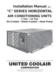
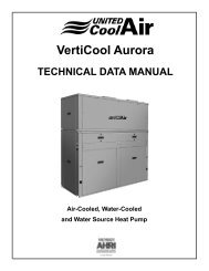
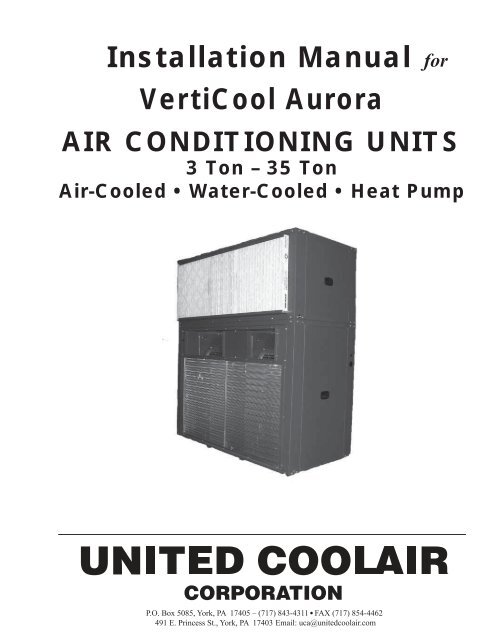
<strong>Installation</strong> <strong>Manual</strong><br />
<strong>VertiCool</strong> <strong>Aurora</strong><br />
for<br />
AIR CONDITIONING UNITS<br />
3 Ton – 35 Ton<br />
Air-Cooled • Water-Cooled • Heat Pump
FORM VAIM 0310<br />
TABLE OF CONTENTS<br />
SECTION 1 – GENERAL INFORMATION<br />
Inspection of Equipment ....................................................4<br />
Location ..............................................................................4<br />
Handling .............................................................................4<br />
Mounting and Setting In Place ...........................................4<br />
Louver and Ducting ............................................................4<br />
Figure 1: Combination Intake/Discharge ...........................5<br />
General Ductwork Recommendations ................................5<br />
Length of Ductwork for Discharge Air ..............................5<br />
Figure 2: Air Velocity Profile .............................................6<br />
Location, Location, Location .............................................6<br />
SECTION 2 – INSTALLATION<br />
Air-Cooled Single Package ................................................7<br />
Condensate Drain Connection ............................................7<br />
Figure 3: Condensate Trap <strong>Installation</strong> ..............................7<br />
Electrical Wiring .................................................................7<br />
Figure 4: Control Wire Sizes ..............................................8<br />
Air-Cooled Units Shipped Split or Split in the Field<br />
Unit <strong>Installation</strong> ............................................................8<br />
Plenum <strong>Installation</strong> .............................................................8<br />
Electric Heat .......................................................................8<br />
Auxiliary Coils (Hot Water or Steam) ................................8<br />
Water Side Economizer (Free Cooling Coil) ......................9<br />
Air Side Economizer ..........................................................9<br />
Clearance ..........................................................................10<br />
Pressure Switches .............................................................10<br />
Water-Cooled Units ..........................................................10<br />
Split Systems ....................................................................11<br />
Chilled Water Sections .....................................................12<br />
SECTION 3 – MAINTENANCE PROCEDURES<br />
Filters ................................................................................13<br />
Cleaning the Water-Cooled Condenser ............................13<br />
Blowers .............................................................................13<br />
Blower Motors ..................................................................13<br />
Blower Speed Adjustment ................................................13<br />
Blower Motor Lubrication ................................................13<br />
Blower Bearing Lubrication .............................................14<br />
Belts ..................................................................................14<br />
Refrigerant Systems .........................................................14<br />
Evaporator and Air-Cooled Condenser Coils ...................15<br />
Hard Start Kit ...................................................................15<br />
SECTION 4 – SEQUENCE OF OPERATION<br />
Cooling Sequence of Operation .......................................16<br />
Heating Sequence of Operation<br />
(other than heat pump) ................................................16<br />
Heat Pump Heating Sequence of Operation .....................17<br />
SECTION 5 – OPTIONS<br />
Condensate Pump .............................................................18<br />
Thermostat ........................................................................18<br />
Checking Hot Gas Bypass Valve ......................................18<br />
Adjustment of Hot Gas Bypass Valve ..............................18<br />
Figure 5: Adding Sixth Contact ........................................18<br />
Steam Coil ........................................................................19<br />
Hot Water Coil ..................................................................19<br />
Chilled Water Valve or Hot Water Valve ..........................19<br />
Flooded Condenser ...........................................................19<br />
Buck/Boost Transformer ..................................................20<br />
Table 1: Buck/Boost Transformer Table ...........................20<br />
Figure 6: Transformer Wiring ...........................................20<br />
Heat Pressure Control Valves ...........................................20<br />
SECTION 6 – TROUBLESHOOTING<br />
Troubleshooting Chart ......................................................21<br />
SECTION 7 – VERTICOOL AURORA SERIES<br />
Basic Model Configurations .............................................25<br />
Air-Cooled Air Path Configurations .................................26<br />
Water-Cooled Air Path Configurations .............................27<br />
Air-Cooled with Air Side Economizer .............................28<br />
Unit Dimensions ...............................................................29<br />
NOMENCLATURE<br />
Verticool <strong>Aurora</strong> Series Basic Model Designation ...........32<br />
3
FORM VAIM 0310<br />
GENERAL INFORMATION<br />
INSPECTION OF EQUIPMENT<br />
Upon receipt of the unit, inspect for visible or concealed<br />
damage. Report any damage to the carrier,<br />
and file a damage claim.<br />
LOCATION<br />
The <strong>VertiCool</strong> <strong>Aurora</strong> has been designed to be<br />
installed as a single package floor mounted unit.<br />
Before the unit is installed, a thorough study should<br />
be made of the structure and proposed installation<br />
location. Careful consideration must be given to<br />
location of wiring, condensate disposal, ductwork<br />
and accessibility for maintenance or service. It is<br />
necessary that a minimum clearance of 36" be allowed<br />
on the front of the cabinet. Some air path<br />
configurations will also require side access to the<br />
evaporator section. Sufficient clearance must be<br />
provided to slide the air filter(s) out, either the left<br />
or right side (30" recommended).<br />
Attention must be given to floor loading<br />
limitations.<br />
Consideration must be made for condensate removal,<br />
either with a trap or condensate pump.<br />
HANDLING<br />
To facilitate handling, the unit is set on<br />
a wooden skid so that it may be picked up with a<br />
two-wheel hand truck or fork lift. Under no circumstances<br />
should the unit or the skid be “walked” on<br />
the corners. Use dolly trucks or pipe rollers to move<br />
the unit to its proper location.<br />
Discharge air from the condenser air outlet<br />
should be deflected away from the condenser<br />
air inlet, to prevent recirculation.<br />
CAUTION: Unit should not be located in<br />
space subject to freezing temperatures.<br />
MOUNTING AND SETTING IN PLACE<br />
The units might be shipped as a single package<br />
or they might be shipped split. Units that<br />
have been ordered with the optional re-sealable<br />
refrigerant fittings can be split in the field to<br />
accommodate moving into position. Sections<br />
are also bolted together.<br />
When re-assembling the evaporator section to the<br />
condensing section, use a sling or other suitable<br />
means that is sufficient to hold the weight of the<br />
section. Use spreader bars to prevent structural<br />
damage to the cabinet during installation.<br />
Make sure that the evaporator section is positioned<br />
correctly for the desired air pattern. Care must be<br />
taken when lowering the evaporator section that<br />
the refrigerant re-sealable fittings are lined up properly<br />
and that they are not damaged in this process.<br />
Re-install the fasteners if removed prior.<br />
LOUVER AND DUCTING<br />
Carefully choosing the right condensing section<br />
intake/exhaust louver(s) and determining the best<br />
location for them are critical components to a successful<br />
<strong>VertiCool</strong> installation.<br />
1. Select a louver design that will safely separate<br />
the discharge from the intake air stream to<br />
ensure that air recirculation will not occur.<br />
2. The intake louver should be designed to minimize<br />
and virtually eliminate water penetration<br />
at a reasonable face area velocity (fpm).<br />
3. The discharge duct must be as short and<br />
straight as possible but of sufficient length to<br />
guarantee uniform airflow distribution through<br />
the louver for maximum velocity.<br />
4. In most cases, the cross-sectional “free area”<br />
of the louver must be equal to or larger than<br />
the cross-sectional areas of the intake and/or<br />
discharge unit openings to allow for optimum<br />
velocity and reasonable pressure drop across<br />
the louver.<br />
4
FORM VAIM 0310<br />
5. Ducts should be insulated if the unit is installed<br />
and operating in cold climates.<br />
6. Adequate access to both the evaporator and<br />
condenser coils as well as the louver must be<br />
available for cleaning purposes.<br />
7. All louver manufacturer instructions, local<br />
codes, and industry accepted guidelines must<br />
be followed for all installations.<br />
The intake and discharge louver can be in separate<br />
frames or combined in one frame.<br />
The combination intake/discharge louver design<br />
offers an advantage over separate louvers because<br />
it requires only one wall opening which decreases<br />
installation costs. However, the blades cannot be<br />
of uniform configuration (i.e. the same blade design<br />
and angle). The discharge louver blades should be<br />
angled to direct the airflow straight out horizontally<br />
from the unit and the intake blades should be angled<br />
down at approximately 45°.<br />
Figure 1: Combination Intake/Discharge<br />
It is critical that the two air streams be directed in<br />
different directions so that no recirculation of discharge<br />
air is allowed to enter the inlet air stream. In<br />
some cases it may be necessary to provide a deflector<br />
vane or separator between the two air streams. If<br />
recirculation of the discharge air does occur, the unit<br />
will likely trip on high head pressure and continue<br />
to fail until the louver design is corrected.<br />
Louvers may be manufactured of aluminum (14<br />
gauge) or steel (18 gauge). Louver widths of 30<br />
inches or more should have additional bracing<br />
midway along the blades to maintain proper blade<br />
separation. If the louvers are to be installed in a<br />
coastal application or any location with environmental<br />
concerns, then the louvers should be treated.<br />
It is also beneficial to angle the bottom of the intake<br />
ductwork up from the louver toward the unit opening<br />
to minimize the possibility of water carryover<br />
reaching the unit and allow for proper drainage.<br />
Louvers should be inspected and cleaned on a regular<br />
basis. A bird screen is required to deter animals<br />
and debris from entering the duct system.<br />
GENERAL DUCTWORK<br />
RECOMMENDATIONS<br />
All ductwork must be designed in accordance with<br />
industry accepted practices. Consult ASHRAE,<br />
AMCA or SMACNA guidelines or standards for<br />
details. Ducts should be insulated in accordance<br />
with ASHRAE Standard 90.1 or per local codes,<br />
particularly if the unit will be operated during cold<br />
weather. We recommend utilizing a suitable flexible<br />
duct connector to minimize or isolate any vibration<br />
transmission to the structure. The condensing unit<br />
intake duct should include a provision to access the<br />
inlet side of the coil for periodic cleaning. It is also<br />
best to design for sufficient clearances for servicing<br />
the blower motors, expansion valves, filters, and<br />
any additional accessories installed.<br />
LENGTH OF CONDENSING SECTION<br />
DUCTWORK FOR DISCHARGE AIR<br />
The <strong>VertiCool</strong> <strong>Aurora</strong> unit should be located a minimum<br />
distance from the louvered wall to maximize<br />
efficiency of the blower. Certain conditions and<br />
obstructions at the fan inlet and outlet adversely<br />
affect fan performance (i.e. elbows, guards, dampers,<br />
etc.). “System Effect” is a term used by the<br />
industry to describe these adverse conditions. It is<br />
best to design the inlet and discharge ductwork to<br />
provide minimum sufficient straight length of duct<br />
to reduce system effect and allow for uniform air<br />
discharge.<br />
5
FORM VAIM 0310<br />
The figure below illustrates the discharge air velocity<br />
profile at various distances from the centrifugal<br />
blower. It is important to determine the 100%<br />
Effective Duct Length to ensure uniform air discharge.<br />
the field. You must know the overall duct design<br />
in order to determine what drive package will be<br />
required. Normal startup procedures should be<br />
followed including balancing the system following<br />
the completed unit installation.<br />
LOCATION, LOCATION, LOCATION<br />
Strategically located intake and discharge louvers<br />
help to prevent recirculation of discharge and contaminated<br />
air into the intake air stream. Airflow<br />
around a building and prevailing wind direction can<br />
adversely affect the potential for recirculation and<br />
should be factored into louver placement.<br />
In some areas, local codes dictate louver location.<br />
Maximize the distance of intake louvers from any<br />
exhaust outlet and other contaminants, people,<br />
property lines, etc. Avoid placing intakes near<br />
idling vehicles.<br />
Figure 2: Air Velocity Profi le<br />
Based on formulas in ASHRAE Fundamentals<br />
– 2009 Duct Design, Chapter 21, the following<br />
minimum intake and discharge 100% Effective<br />
Duct Lengths (EDL) are recommended:<br />
• 3 thru 6 tons = 3.5 feet<br />
• 8 tons = 4.5 feet<br />
• 10 tons = 5.5 feet<br />
• 12 tons = 5 feet<br />
• 15 tons = 5.5 feet<br />
• 20 tons = 6.5 feet<br />
• 25 thru 30 tons = 8 feet<br />
• 35 tons = 9.5 feet<br />
The <strong>VertiCool</strong> units are supplied with a standard<br />
motor and drive package which provides approximately<br />
0.25" ESP. Upgrades (optional) are available<br />
that can raise this capability to 1" ESP. The<br />
drive packages have some ability to be adjusted in<br />
The bottom of the intake louver should be raised<br />
a minimum of 12" from a horizontal surface (roof,<br />
sidewalk, etc.) to prevent blockage from debris.<br />
If snow accumulations are expected to be greater<br />
than 12", raise the bottom of the louver above the<br />
average snowfall depth.<br />
If more than one <strong>VertiCool</strong> unit will be installed in<br />
the same area, then the minimum separation of one<br />
unit adjacent to another should be 6 feet. A 10 foot<br />
separation distance should be maintained where two<br />
units are installed one above the other. It is best to<br />
direct discharge air up and away from pedestrian<br />
walkways as well.<br />
We do not recommend multiple installations between<br />
closely situated buildings where discharge<br />
air could collect and be directed back to the intake.<br />
Again, recirculation will cause the unit to trip on<br />
high head pressure.<br />
Avoid locating any inlet louver where vehicles will<br />
be idling.<br />
6
FORM VAIM 0310<br />
INSTALLATION<br />
The <strong>VertiCool</strong> <strong>Aurora</strong> units can be shipped as<br />
a single package or as a split package which is<br />
assembled in the field.<br />
AIR-COOLED SINGLE PACKAGE<br />
1. Move the unit to the desired installation<br />
location.<br />
2. Unit contains a full charge of R-410a<br />
refrigerant.<br />
3. Install the unit so that controls and access<br />
panels are accessible to the operator and maintenance<br />
personnel.<br />
4. Install the condensing section ductwork<br />
following the guidelines and industry<br />
accepted practices for the condenser air inlet and<br />
discharge.<br />
5. Install ductwork on the evaporator as required.<br />
If the unit was provided with a discharge<br />
plenum having grilles, no ductwork would<br />
be required.<br />
CONDENSATE DRAIN CONNECTION<br />
Install a condensate trap or a condensate pump as<br />
required. Route the condensate disposal tubing to<br />
a suitable location.<br />
Units are equipped with two evaporator drain connections.<br />
The 3 through 15-ton units are 1" IPS<br />
while the 20 through 35-ton units are 1-1/4" IPS.<br />
It is only necessary that one drain connection be<br />
utilized. Make sure that the drain connection not<br />
being used is plugged.<br />
The drain line must be trapped because the coils<br />
are located on the negative side of the blower(s).<br />
The purpose of the condensate trap is to neutralize<br />
the negative pressure created within the cabinet by<br />
the blower.<br />
This negative pressure can vary from less than 1"<br />
up to 2" water column. The condensate trap must<br />
be of sufficient depth in water column to permit the<br />
condensate to flow from the drain pan.<br />
7<br />
The “A” dimension must equal or exceed the<br />
negative static pressure developed by the supply air<br />
blower. If it does not, the condensate will not drain<br />
properly and may overflow the drain pan. The trap<br />
must be at least 2-1/2" deep to maintain a water seal<br />
under all operating conditions, especially during<br />
blower start-up.<br />
UNIT<br />
Figure 3: Condensate Trap <strong>Installation</strong><br />
ELECTRICAL WIRING<br />
1. Refer to the wiring diagram that was included<br />
with the unit.<br />
2. Units are completely internally wired at the<br />
factory.<br />
3. All units are provided with terminal blocks.<br />
4. Check the unit data tag for the required voltage,<br />
minimum circuit ampacity and maximum<br />
fuse size.<br />
5. Route the power wiring through one of the<br />
holes provided in the front corner posts.<br />
6. Power wiring must comply with all National<br />
and Local codes. The power supply must be<br />
suitably fused for wire protection.<br />
7. Use copper conductors only. The unit must be<br />
earth grounded using the ground lug provided<br />
in the electrical box.<br />
NOTE: Metal conduit is not an acceptable<br />
ground.<br />
8. Specific codes require that each unit must have<br />
a field provided method to disconnect main<br />
power installed within sight of the unit.<br />
"A"<br />
2-1/2"
FORM VAIM 0310<br />
Wire Size 1 AWG. Gauge<br />
22 20 19 18 16<br />
40 120 150 190 305<br />
Maximum Wire Length 2 Feet<br />
Notes:<br />
1. Solid, Class II copper wire<br />
2. Based on a voltage drop of 1.2 volts per wire.<br />
3. Total wire length is from unit to room thermostat,<br />
and back to unit.<br />
FIGURE 4: Control Wire Sizes<br />
9. Select a location to install the thermostat to<br />
avoid vibration, drafts, sun exposure or internal<br />
heat sources. Use an inside wall.<br />
10. Route the correct low voltage wire type and<br />
size back to the unit and through one of the<br />
holes provided in the front corner posts.<br />
Connect to the low voltage terminal block per<br />
the wiring diagram supplied.<br />
AIR-COOLED UNITS SHIPPED<br />
SPLIT OR SPLIT IN THE FIELD<br />
UNIT INSTALLATION<br />
1. Move the unit to the desired installation<br />
location.<br />
2. Unit contains a full charge of R-410a refrigerant.<br />
3. Install the unit so that controls and access<br />
panels are accessible to the operator and maintenance<br />
personnel.<br />
4. Install the condensing section ductwork<br />
following the guidelines and industry accepted<br />
practices for the condenser air inlet and<br />
discharge.<br />
5. When re-assembling the evaporator section<br />
to the condensing section, use a sling or other<br />
suitable means that is sufficient to hold the<br />
weight of the section. Use spreader bars to<br />
prevent structural damage to the cabinet during<br />
installation.<br />
6. Make sure that the evaporator section is positioned<br />
correctly for the desired air pattern.<br />
Care must be taken when lowering the evaporator<br />
section that the refrigerant re-sealable<br />
fittings are lined up properly and that they are<br />
not damaged in this process. Re-install the<br />
fasteners if removed prior.<br />
7. Install ductwork on the evaporator as required.<br />
If the unit was provided with a discharge<br />
plenum having grilles, no ductwork would<br />
be required.<br />
8. Install the condensate trap as outlined above.<br />
9. Wire the unit as outlined above.<br />
PLENUM INSTALLATION<br />
The plenum is typically installed at the factory.<br />
However, it may need to be removed to move the<br />
unit into position. The plenum is held in position<br />
with sheet metal screws.<br />
If the plenum has discharge grilles, the grilles will<br />
have to be removed to take the plenum off for reinstallation<br />
on the evaporator section.<br />
ELECTRIC HEAT<br />
Electric heat is typically located in the return air<br />
stream. It is located between the filters and the<br />
evaporator coil.<br />
On larger units having 80 kW or more of electric<br />
heat, a second power supply is required. Run the<br />
second power supply to the connections located<br />
with the heater. Follow all National Electrical Codes<br />
and Local Codes as required. Make sure to run a<br />
ground wire to the supplied lug.<br />
Route the low voltage wiring for the heater control<br />
to the low voltage terminal block located with the<br />
heater.<br />
AUXILIARY COILS (HOT WATER<br />
OR STEAM)<br />
A hot water coil or steam coil when used as heat<br />
will be located in the return air stream between the<br />
filters and the evaporator coil. Hot water coils may<br />
also be located after the evaporator coil. These are<br />
typically installed at the factory.<br />
Some units will include Jack Stands to support the<br />
auxiliary coil / filter box. If the unit is shipped as<br />
a single package the jack stands will be attached.<br />
Care should be taken when moving the unit from<br />
8
FORM VAIM 0310<br />
the skid to the installation location so as not to tear<br />
or loosen the jack stand where it is attached to the<br />
cabinet.<br />
If the evaporator section is shipped loose the auxiliary<br />
coil section will be attached to the evaporator.<br />
The jack stands, if required, will be placed inside<br />
the auxiliary coil section. The mounting hardware<br />
will be attached to the jack stand flange.<br />
If an optional hot water valve is ordered, this will<br />
be shipped loose for installation in the field.<br />
Control wiring will need to be installed from the<br />
hot water valve back to the unit control panel. Follow<br />
all National Electrical Codes and Local Codes<br />
as required.<br />
Any steam valves and other adjunct steam<br />
components will be field supplied and installed<br />
by others.<br />
Control wiring will need to be installed from the<br />
steam valve back to the unit control panel. Follow<br />
all National Electrical Codes and Local Codes as<br />
required.<br />
A pan is included under any hot water coil or steam<br />
coil. A condensate trap will need to be installed for<br />
this drain pan. A trap will need to be installed since<br />
this line is in a negative air stream. Follow the same<br />
procedures for this line as for the unit condensate<br />
drain line outlined on page 7.<br />
Pipe the hot water coil or steam coil per industry<br />
accepted practices.<br />
WATER SIDE ECONOMIZER (FREE<br />
COOLING COIL)<br />
A water side economizer coil will be located in<br />
the return air stream between the filters and the<br />
evaporator coil. These are typically installed at the<br />
factory.<br />
Some units will include Jack Stands to support the<br />
water side economizer / filter box. If the unit is<br />
shipped as a single package the jack stands will be<br />
attached. Care should be taken when moving the<br />
9<br />
unit from the skid to the installation location so as<br />
not to tear or loosen the jack stand where it is attached<br />
to the cabinet.<br />
If the evaporator section is shipped loose the water<br />
side economizer section may or may not be attached<br />
to the evaporator. The jack stands, if required, will<br />
be placed inside the water side economizer section.<br />
The mounting hardware will be attached to the jack<br />
stand flange.<br />
If the unit is shipped as a single package, the water<br />
piping from the unit to water side economizer coil<br />
will be factory installed.<br />
If the water side economizer is shipped as a separate<br />
section or if the unit comes with the evaporator and<br />
water side economizer as a section, the water piping<br />
will be shipped loose for field attachment.<br />
A condensate pan is included under the water side<br />
economizer coil. A condensate trap will need to be<br />
installed for this drain pan. A trap will need to be<br />
installed since this line is in a negative air stream.<br />
Follow the same procedures for this line as for the<br />
unit condensate drain line on page 7.<br />
AIR SIDE ECONOMIZER<br />
The air side economizer option is installed on the<br />
rear of the cabinet.<br />
Some units will include Jack Stands to support<br />
the air side economizer / filter box. If the unit is<br />
shipped as a single package the jack stands will<br />
be attached. Care should be taken when moving<br />
the unit from the skid to the installation location<br />
so as not to tear or loosen the jack stand where it<br />
is attached to the cabinet.<br />
If the evaporator section is shipped loose the air side<br />
economizer section may or may not be attached to<br />
the evaporator. The jack stands, if required, will be<br />
placed inside the air side economizer section. The<br />
mounting hardware will be attached to the jack<br />
stand flange.<br />
The enthalpy sensors for the return air and the<br />
outside air are shipped loose for field mounting.
FORM VAIM 0310<br />
Follow the instructions with each sensor for the<br />
proper location and mounting.<br />
Field supplied low voltage wiring must be installed<br />
between the two sensors and the terminal blocks<br />
located in the unit control panel. Make sure to use<br />
the correct type and wire gauge size.<br />
When ducting to the air side economizer, flexible<br />
duct collars should be utilized to avoid any transmission<br />
of vibration into the duct work.<br />
CLEARANCE<br />
Clearance of 36" is required on the front side of all<br />
units for service and maintenance access.<br />
If a unit has front return, 30" clearance on each side<br />
of the unit must be provided for access to the motor<br />
and / or refrigerant circuit components, such as the<br />
thermostatic expansion valve(s).<br />
Filters can be accessed from either side of the unit.<br />
Sufficient space must be provided for removal and<br />
replacement of all the filters. This can be from one<br />
side only or from both sides.<br />
PRESSURE SWITCHES<br />
High Pressure<br />
This switch shuts the compressor it is connected<br />
to down in the event of excessive high pressure in<br />
the discharge line. A manual reset is required at the<br />
high pressure switch.<br />
Low Pressure<br />
This switch shuts the compressor it is connected<br />
to down in the event of excessive low pressure in<br />
the suction line.<br />
NOTE: The low pressure switch(es) are connected<br />
to lock out relay(s). If a compressor<br />
goes off on low pressure, the lock out relay(s)<br />
must be reset by switching the thermostat to<br />
the “OFF” position and then back to the<br />
“COOL” position.<br />
WATER-COOLED UNITS<br />
Water-Cooled Condenser<br />
The condenser is a tube-in-tube, chemically cleanable<br />
configuration. The inner tube carries the water<br />
and the outer tube the refrigerant.<br />
Water Piping and Connections<br />
Do not reduce the water pipe sizes from the factory<br />
connections on the unit. Both the water inlet<br />
and outlet of the condensing section should be<br />
equipped with field supplied shut off valves. This<br />
is needed for shutdown of water supply during<br />
long periods of unit shutdown and/or condenser<br />
removal, if required.<br />
The condensate drain line should not be connected<br />
to the condenser outlet, as flooding<br />
will occur.<br />
Provisions should be made for ease of pipe<br />
cleaning by using plugged tees at all turns,<br />
rather than ordinary elbows.<br />
Hook Up<br />
Each refrigerant circuit requires 3 gallons per minute<br />
(GPM) of water per ton of refrigeration. If the<br />
unit does not have water regulating valves or head<br />
pressure control valves, field supplied balancing<br />
valves may be required. For future reference when<br />
cleaning is needed, record details on temperatures<br />
entering and leaving the heat exchanger and the<br />
pressure drop as a new installation during the initial<br />
unit start-up. See “Cleaning The Water-Cooled<br />
Condenser” on page 14.<br />
Water Connection<br />
Install and connect a fresh water strainer (field<br />
supplied) to the water inlet line. Strainer should be<br />
readily accessible for periodic cleaning. Shut off<br />
valves on both strainer inlet and outlet are recommended<br />
to facilitate cleaning.<br />
CAUTION: High inlet water temperature or<br />
low water flow rate may result in nuisance<br />
tripping of the high pressure switch.<br />
10
FORM VAIM 0310<br />
CAUTION: Water-cooled units with a glycol<br />
cooling fluid will require a higher GPM / Ton<br />
flow rate. Contact the factory for details.<br />
NOTE: Optional Head Pressure Control<br />
Valve(s) should be incorporated into the unit<br />
circuit(s) if the cooling fluid will be less than<br />
65° F.<br />
WARNING: Water-cooled units are for use<br />
with fresh water applications only. Do not<br />
use for brackish water or salt water unless<br />
appropriate condensers have been installed<br />
as an option.<br />
SPLIT SYSTEMS<br />
Evaporator Mounting<br />
In some situations it is necessary to install the system<br />
split. The evaporator section may be supplied with<br />
the lower section for floor mounting. The evaporator<br />
can also be supplied as a stand-alone section.<br />
When being used as a stand-alone evaporator section<br />
care must be taken to properly support the<br />
section if suspended. It is advisable to provide a<br />
full perimeter frame to assure that the sheet metal<br />
does not buckle.<br />
Care must be taken when mounting the evaporator<br />
to assure that adequate service clearance is provided<br />
for access to the components. Make sure that the access<br />
panels can be removed. Confirm that no items,<br />
such as electrical lines/conduit or water piping, are<br />
routed in front of removable access panels.<br />
The evaporator section will have a control panel.<br />
Dependent upon the system components this control<br />
panel may be located internal to the evaporator or<br />
externally. Wire high and low voltage to this section<br />
as required following National Electrical Codes and<br />
Local Codes.<br />
NOTE: Make sure to use the appropriate<br />
gauge of low voltage wire based on the total<br />
wire length so that no more than a 1.2 volt<br />
drop is experienced.<br />
On larger units having 80 kW or more of electric<br />
heat, a second power supply is required. Run the<br />
second power supply to the connections located<br />
with the heater. Follow all National Electrical Codes<br />
and Local Codes as required. Make sure to run a<br />
ground wire to the supplied lug.<br />
Provide field supplied and installed vibration isolation<br />
as required.<br />
11
FORM VAIM 0310<br />
CHILLED WATER SECTIONS<br />
The chilled water section may be supplied<br />
with the lower section for floor mounting. The<br />
chilled water section can also be supplied as a<br />
standalone section.<br />
When being used as a standalone chilled water<br />
section, care must be taken to properly support the<br />
section if suspended. It is advisable to provide a<br />
full perimeter frame to assure that the sheet metal<br />
does not buckle.<br />
Provide field supplied and installed vibration isolation<br />
as required.<br />
Care must be taken when mounting the chilled water<br />
section to assure that adequate service clearance is<br />
provided for access to the components. Make sure<br />
that the access panels can be removed.<br />
or externally. Wire high and low voltage to this<br />
section as required following National Electrical<br />
Codes and Local Codes.<br />
NOTE: Make sure to use the appropriate<br />
gauge of low voltage wire based on the total<br />
wire length so that no more than a 1.2 volt<br />
drop is experienced.<br />
On larger units having 80 kW or more of electric<br />
heat, a second power supply is required. Run the<br />
second power supply to the connections located<br />
with the heater. Follow all National Electrical Codes<br />
and Local Codes as required. Make sure to run a<br />
ground wire to the supplied lug.<br />
Install the chilled water valve per industry accepted<br />
practices.<br />
The chilled water section will have a control panel.<br />
Dependent upon the system components, this control<br />
panel may be located internal to the evaporator<br />
12
FORM VAIM 0310<br />
MAINTENANCE PROCEDURES<br />
FILTERS<br />
Do NOT run unit without filters.<br />
Throwaway filters are supplied which are pleated<br />
extended surface type. Filters should be checked<br />
monthly for dirt accumulation and changed when<br />
necessary. Replacement filters must be the same<br />
type as originally supplied.<br />
NOTE: Unit must be shut off at the disconnect<br />
switch before the filters are serviced. Be<br />
sure to check that the air flow direction arrows<br />
on the filters point in the correct direction<br />
of air flow.<br />
CLEANING THE WATER-COOLED<br />
CONDENSER<br />
Refer to document “Cleaning a Water-Cooled<br />
Condenser (Maintenance Procedure)”, which can<br />
be found on the web site at www.unitedcoolair.com<br />
in the Miscellaneous section of the DOWNLOAD<br />
category.<br />
BLOWERS<br />
Disconnect power and lockout service before doing<br />
any service or maintenance.<br />
Air-cooled units are provided with adjustable belt<br />
drive blower packages for both the evaporator and<br />
condensing sections. Check that the blower wheel<br />
is tight on the shaft and does not contact the housing.<br />
Bearings are permanently sealed, but should be<br />
checked periodically for signs of wear. Check for<br />
restrictions or foreign material in the air circuit.<br />
The drive may be adjusted for different static pressures.<br />
If such an adjustment is made, check that<br />
the motor current draw does not exceed the motor<br />
nameplate current by more than 10%.<br />
On units with three-phase fan motors, check<br />
for proper blower rotation at start-up. If they<br />
run backwards, interchange two of the incoming<br />
power leads.<br />
BLOWER MOTORS<br />
All blower motors are equipped with thermal overload<br />
protectors, either built-in the motor or in the<br />
control box.<br />
CAUTION: Open disconnects to unit, as<br />
motor will start when automatic thermal<br />
overload resets.<br />
BLOWER SPEED ADJUSTMENT<br />
Blower speed may be changed by adjusting the variable<br />
diameter sheave provided on the blower drive<br />
motor. Sheave may be adjusted by removing the belt<br />
and loosening the setscrew located in the hub of the<br />
outer flange. With the setscrew loosened, the flange<br />
may be turned clockwise to increase blower speed<br />
or counter-clockwise to reduce blower speed.<br />
Typically the motor and drive packages have been<br />
sized and designed for the specific CFM and external<br />
static pressure (ESP) of the application. Before making<br />
any changes confirm what the performance was<br />
designed for and what the actual performance is.<br />
CAUTION: Setscrew must be positioned<br />
directly above the flat section of the threaded<br />
sheave shaft before tightening to hold<br />
adjustment.<br />
CAUTION: reduction of airflow through<br />
excessive external air friction losses, lowered<br />
blower speed, operation with dirty<br />
filters, or obstructed air flow may result in<br />
excessive condensation at air outlets, short<br />
cycling, or total unit shutdown due to<br />
evaporator coil icing.<br />
NOTE: Verify that the motor current draw<br />
does not exceed the motor nameplate current<br />
by more than 10%.<br />
BLOWER MOTOR LUBRICATION<br />
Motor manufacturers indicate that motors never<br />
need relubrication, but if units run continuously,<br />
13
FORM VAIM 0310<br />
it is recommended that they be re-lubricated every<br />
5500 hours for 3600 RPM motors and 10,000 hours<br />
for 1800 RPM motors. If unit motors are run in a<br />
cyclical manner, lubrication is recommended every<br />
5 years.<br />
If the unit has been inactive or in storage for over<br />
a year, relubricate before starting.<br />
Use Polyrex EM, Texaco Polystar, Pennzoil Penn<br />
#2 or Chevron SRI #2 lubricant or equivalent in<br />
the following quantities: 0.6 cu. in. or 2 teaspoons,<br />
approximately 1 1/2 to 2 handle pumps using a<br />
standard grease gun. Keep grease clean, and do not<br />
mix dissimilar greases.<br />
Clean area around fitting. Remove purge plug (only<br />
on larger motors) for greasing, and replace after<br />
at least 20 minutes of operation after greasing.<br />
For safety, we recommend relubricating while the<br />
motor is stopped.<br />
Rotate the motor by hand as the grease is being applied<br />
to avoid air pockets. Over greasing, either in<br />
quantity or speed of injection, can cause premature<br />
bearing failure. Apply the recommended quantity<br />
of grease gradually.<br />
CAUTION: Disconnect power and lockout<br />
service before doing any service or maintenance<br />
to the unit.<br />
BLOWER BEARING LUBRICATION<br />
Bearings on the smaller units are permanently<br />
sealed, but should be checked periodically for signs<br />
of wear.<br />
Larger units have pillow block bearings. Bearings<br />
will need to be lubricated based on the use of the<br />
equipment.<br />
DUTY<br />
Low Usage<br />
Periodic<br />
Continuous<br />
GREASE INTERVAL<br />
12 Months<br />
6 Months<br />
1 – 2 Months<br />
Use a high quality lithium grease for blower pillow<br />
block bearings. Wipe off the “Zerk” fitting with a<br />
rag before adding grease so as not to introduce dirt<br />
into the bearing.<br />
Slowly rotate the shaft while pumping it in. Pump<br />
the grease in slowly so as not to blow out the bearing<br />
seal. When the grease starts to “seep” out of the<br />
bearing you have put in enough new lubricant.<br />
Over lubricating can cause a bearing to fail from<br />
overheating or it can blow out the seal.<br />
Wipe off the “Zerk” fitting with a rag after adding<br />
grease.<br />
BELTS<br />
Drive belts should be examined periodically for<br />
wear and for correct tension. Belts that are too tight<br />
cause bearing wear while belts that are too loose<br />
cause slippage. If the midpoint (midway between<br />
the blower and motor shaft) of the belt is pressed<br />
inward, there should be about 1/2” to a 1” of deflection<br />
when the belt is properly tensioned. Belt<br />
tension can be adjusted by means of the adjusting<br />
bolt, which requires loosening of a nut to move the<br />
motor and change belt position.<br />
REFRIGERANT SYSTEMS<br />
All refrigerant circuits contain a liquid line sight<br />
glass. If bubbles appear in the sight glass, the system<br />
is either undercharged with refrigerant or there<br />
may be a restriction in the liquid line upstream of<br />
the sight glass. However, bubbles will appear every<br />
now and then in units with the hot gas bypass<br />
option. Bubbles will also appear upon compressor<br />
start up, but normally clear to pure liquid after a<br />
few minutes of operation.<br />
It should be noted that systems using R-410a<br />
refrigerant may not run clear and may have<br />
a “washed look”.<br />
The sight glass contains a moisture indicator which<br />
changes color when moisture is present in the refrigerant<br />
circuit. This indicator is the circular dot<br />
in the center of the sight glass. If the color of this<br />
14
FORM VAIM 0310<br />
indication is “DRY”, the refrigerant is okay. When<br />
the indication is “WET”, an abnormal condition<br />
exists, servicing is required.<br />
NOTE: After installation and during equipment<br />
start up, the sight glass may indicate<br />
a “WET” condition. This occurs during<br />
prolonged periods of non-operation and<br />
should indicate “DRY” after several hours<br />
(up to 12) of operation.<br />
EVAPORATOR AND AIR-COOLED<br />
CONDENSER COILS<br />
Check semi-monthly the condition of the face of<br />
both the evaporator and condenser coils.<br />
A dirty condenser coil will cause high condensing<br />
pressures, resulting in higher power consumption<br />
and possibly system shut-down by high-pressure<br />
safety control. A dirty evaporator coil will reduce<br />
unit capacity and eventually will cause shut-down<br />
by the low pressure safety control.<br />
HARD START KIT<br />
A start assist device is utilized on all single-phase<br />
units. The purpose of this device is to assist the compressor<br />
in starting under low voltage conditions.<br />
A capacitor in conjunction with a Positive Temperature<br />
Coefficient (PTC) relay is installed across<br />
the run and start windings of the motor. The PTC<br />
device utilizes a ceramic element with a predictable<br />
thermal response to the introduction of electric current.<br />
When the compressor is called upon to start,<br />
the start capacitor provides a voltage boost to the<br />
start winding of the motor and causes the motor to<br />
turn. As the starting current is introduced across the<br />
start windings, the PTC element begins to warm.<br />
When the PTC device reaches approximately 250°F<br />
(corresponding to 0.6-0.8 seconds), the resistance<br />
in the element increases and creates an open switch<br />
that releases the start winding from the circuit and<br />
the motor continues to run. If the compressor does<br />
not start before the device heats to 250°F, it will not<br />
start until the PTC device cycles through a cooldown<br />
period (usually 2-3 minutes). A compressor<br />
off-cycle timer is included in the electrical circuit<br />
for this purpose.<br />
The time delay relay also helps the refrigerant<br />
system pressures to equalize at the end of the run<br />
cycle. This helps the compressor during the starting<br />
process in that it is not attempting to start against a<br />
high discharge pressure.<br />
The installer should verify that this timer<br />
is set for 3 or more minutes.<br />
15
FORM VAIM 0310<br />
SEQUENCE OF OPERATION<br />
COOLING SEQUENCE OF OPERATION<br />
1. Before starting the unit, make sure electrical<br />
power has been turned on for a minimum of 24<br />
hours. This assures that any liquid refrigerant<br />
is “driven” out of the crankcase (crankcase<br />
heater is optional).<br />
2. For water-cooled units, make sure condenser<br />
water is available. Open all shut off valves and<br />
make sure all air is purged from the water circuit.<br />
Verify that the cooling tower is functioning,<br />
if this is the source of condensing water<br />
supply. Start circulating the water to the water<br />
condenser.<br />
3. The following sequence is based on the unit<br />
being controlled by a room thermostat. If another<br />
control type is being utilized, reference<br />
the instructions for that device.<br />
a. Raise thermostat setpoint to highest level.<br />
b. Set System switch to “OFF” position.<br />
c. Set Fan switch to the “AUTO” position.<br />
d. Moving the Fan switch to the “ON” position<br />
should cause the evaporator blower<br />
motor to run. Moving the Fan Switch back<br />
to “AUTO” should stop the blower.<br />
e. Move the System switch to the “COOL” position.<br />
Slowly lower the thermostat setting<br />
to call for cooling. The evaporator blower<br />
should start (assuming the Fan switch is set<br />
to “AUTO”) and the System No. 1 compressor<br />
should start.<br />
f. On those units with multiple compressors,<br />
if the thermostat setpoint continues to<br />
be lowered, the second compressor should<br />
then start.<br />
g. Set room thermostat at desired space temperature<br />
and the Fan switch to “AUTO” or<br />
“ON”. The unit will cycle as required to<br />
maintain conditions.<br />
4. Chilled water sequence is the same as above,<br />
except compressor activation is replaced by<br />
the chilled water valve function.<br />
5. Heat pump cooling sequence is the same as<br />
above, except the reversing valve will also<br />
be activated when the compressor cycle is<br />
started.<br />
HEATING SEQUENCE OF OPERATION<br />
(OTHER THAN HEAT PUMP)<br />
1. The following sequence is based on the unit<br />
being controlled by a room thermostat. If another<br />
control type is being utilized, reference<br />
the instructions for that device.<br />
a. Lower thermostat setpoint to the lowest<br />
level.<br />
b. Set System switch to “OFF” position.<br />
c. Set Fan switch to “AUTO” position.<br />
d. Moving the Fan switch to the “ON” position<br />
should cause the evaporator blower<br />
motor to run. Moving the Fan switch back<br />
to “AUTO” should stop the blower.<br />
e. Move the System switch to the “HEAT”<br />
position. Slowly raise the thermostat setting<br />
to call for heating. The evaporator blower<br />
should start (assuming the Fan switch is<br />
set to “AUTO”) and the electric heating<br />
element will be activated.<br />
f. On those units with a second stage of electric<br />
heat, if the thermostat setpoint continues to<br />
be raised, the second stage of electric heat<br />
should then be activated.<br />
NOTE: Units with more than one stage of<br />
electric heat require a two stage heat thermostat.<br />
g. Set room thermostat at desired space temperature<br />
and set the Fan switch to “AUTO”<br />
or “ON”. The unit will cycle as required to<br />
maintain conditions.<br />
16
FORM VAIM 0310<br />
HEAT PUMP HEATING SEQUENCE<br />
OF OPERATION<br />
NOTE: Confirm that a heat pump thermostat<br />
has been used for this application.<br />
1. Before starting the unit, make sure electrical<br />
power has been turned on for a minimum of 24<br />
hours. This assures that any liquid refrigerant<br />
is “driven” out of the crankcase (crankcase<br />
heater is optional).<br />
2. For water-cooled units, make sure condenser<br />
water is available. Open all shut off valves<br />
and make sure all air is purged from the water<br />
circuit. Verify that cooling tower is functioning,<br />
if this is the source of condensing water<br />
supply. Start circulating the water to the water<br />
condenser.<br />
3. The following sequence is based on the unit<br />
being controlled by a room thermostat. If another<br />
control type is being utilized, reference<br />
the instructions for that device.<br />
a. Lower thermostat setpoint to the lowest<br />
level.<br />
b. Set System switch to “OFF” position.<br />
c. Set Fan switch to “AUTO” position.<br />
d. Moving the Fan switch to the “ON” position<br />
should cause the evaporator blower<br />
motor to run. Moving the Fan switch back<br />
to “AUTO” should stop the blower.<br />
e. Move the System switch to the “HEAT”<br />
position. Slowly raise the thermostat setting<br />
to call for heating. The evaporator blower<br />
should start (assumes Fan switch set to<br />
“AUTO”) and the System No. 1 compressor<br />
will start.<br />
f. On those units with multiple compressors,<br />
if the thermostat setpoint continues to be<br />
raised, the second compressor should then<br />
start.<br />
g. Set room thermostat at desired space temperature.<br />
Set the Fan switch to “AUTO” or<br />
“ON”. The unit will cycle as required to<br />
maintain conditions.<br />
17
FORM VAIM 0310<br />
CONDENSATE PUMP<br />
If the unit includes the External Condensate Pump<br />
option, please refer to Form EXT PUMP IOM<br />
(0410) for <strong>Installation</strong> and Operation.<br />
THERMOSTAT<br />
Standard units (no heating) with one compressor require<br />
single stage thermostats, cool only. Units with<br />
two require dual stage thermostats, cool only.<br />
When a programmable thermostat is used, three<br />
connections must be made from “c”. . . to the<br />
programmable thermostat, to a ground and to<br />
the 24 volt coil of the evaporator fan motor contactor.<br />
See Figure 5.<br />
Heat pump units and units with auxiliary electric<br />
heat (either integral in unit or in duct) require single<br />
stage, cool/heat heat pump thermostats if units have<br />
only one compressor. Units with two compressors<br />
require dual stage heat pump thermostats with cool/<br />
heat functions.<br />
CHECKING HOT GAS BYPASS<br />
1. Using a calibrated meter, connect a thermocouple<br />
lead to the outlet line at the hot gas<br />
bypass valve. Tie wrap and insulate the lead.<br />
2. Connect a low pressure refrigerant gauge to<br />
the suction line service port.<br />
3. Connect a high pressure refrigerant gauge to<br />
the liquid line service port.<br />
4. Operate air conditioner in the cooling mode<br />
until system is stabilized. (Approximately 15<br />
minutes)<br />
5. If the high side pressure is not at or above 420<br />
psig, block off the condenser inlet air stream<br />
until the pressure is above this threshold. This<br />
will simulate a system performance level close<br />
to the design condition of 95° F ambient.<br />
6. The hot gas bypass valve setting is 104 psig.<br />
a. If the suction pressure is 104 psig the thermocouple<br />
reading should be approximately<br />
OPTIONS<br />
18<br />
117° F or higher. Please note that it may be<br />
necessary to block off some of the evaporator<br />
air in order to check this condition.<br />
b. If the suction pressure is above 104 psig the<br />
thermocouple reading should be less than<br />
117° F.<br />
c. If the suction pressure is below 104 psig the<br />
hot gas bypass valve should be adjusted to<br />
raise the pressure.<br />
ADJUSTMENT OF HOT GAS BYPASS<br />
VALVE<br />
The function of the hot gas bypass valve is to prevent<br />
the suction pressure from falling below a predetermined<br />
set point, thereby balancing the system.<br />
The set point is typically 104 psig (R-410a).<br />
Refer to the procedure below for Checking the Hot<br />
Gas Bypass Valve before proceeding. This will help<br />
to establish where the valve is currently set.<br />
1. Connect a low pressure refrigerant gauge to<br />
the suction line.<br />
2. Operate air conditioner in the cooling mode<br />
until system is stabilized. (Approximately<br />
15 minutes)<br />
3. Remove the seal cap that covers the adjustment<br />
screw of the hot gas bypass valve.<br />
4. Adjust the valve by turning the stem. A<br />
Programmable Thermostat<br />
Evaporator Fan<br />
24 Volt Coil<br />
New Sixth<br />
Contact To Be Added<br />
Terminal<br />
Board<br />
Figure 5: Adding Sixth Contact<br />
3<br />
R<br />
G<br />
Y1<br />
Y2<br />
T<br />
C<br />
Evaporator<br />
Section<br />
Enclosure<br />
2<br />
1<br />
Ground<br />
0004CA
FORM VAIM 0310<br />
CLOCKWISE turn will increase the pressure<br />
setting. A COUNTERCLOCKWISE<br />
turn will decrease the pressure setting. One<br />
complete turn is equal to approximately a 4<br />
psi change.<br />
Adjustments should be made in small increments,<br />
allowing the system to stabilize after<br />
each turn.<br />
5. Vary the evaporator load to test at various conditions<br />
that the suction pressure does not fall<br />
below the set point (104 psig for R-410a).<br />
6. Replace the seal cap on the hot gas bypass<br />
valve.<br />
NOTE:<br />
a. On split system applications the hot gas<br />
bypass line to the evaporator should be insulated<br />
to prevent condensation.<br />
b. Use a wet rag around the hot gas bypass<br />
valve when doing any brazing<br />
STEAM COIL<br />
The steam coil is located in the return air. The coil<br />
is copper tube/aluminum fin. Connections exit the<br />
cabinet at the coil location. Standard steam coils and<br />
non-freeze steam coils are available. Controls and<br />
valves for steam coils are supplied by others. (See<br />
also the section on Steam Coils in the <strong>Installation</strong><br />
Section, Page 8)<br />
HOT WATER COIL<br />
The hot water coil is located in the return air, either<br />
before or after the evaporator. The coil is copper<br />
tube/aluminum fin. Connections exit the cabinet at<br />
the coil location. Controls and valves for hot water<br />
coils are typically supplied by others. (See also the<br />
section on Hot Water Coils in the <strong>Installation</strong> Section,<br />
Page 8).<br />
CHILLED WATER VALVE OR HOT<br />
WATER VALVE<br />
Chilled water or hot water valves, if supplied by<br />
<strong>United</strong> <strong>CoolAir</strong>, are typically 2-way. The valve<br />
would be shipped loose for installation in the field.<br />
The valve is to be mounted in the outlet line of<br />
the coil.<br />
FLOODED CONDENSER<br />
When the outdoor ambient temperature falls, the<br />
condensing pressure falls. This causes the discharge<br />
pressure to fall. Since the pressure differential<br />
across the thermostatic expansion valve port affects<br />
the rate of refrigerant flow, low discharge pressure<br />
generally causes insufficient refrigerant to be fed<br />
to the evaporator. Failure to have sufficient head<br />
pressure will result in low suction pressure and/or<br />
iced evaporator coils. The effective range for this<br />
option is down to -30°F.<br />
The purpose of a flooded condenser is to hold back<br />
enough of the condensed liquid refrigerant so that<br />
some of the condenser surface is rendered inactive.<br />
This reduction of active condensing surface results<br />
in a rise in condensing pressure and sufficient liquid<br />
line pressure for normal system operation.<br />
A three-way modulating valve and a receiver make<br />
up the flooded condenser refrigerant components.<br />
The valve is placed in the liquid line after the condenser.<br />
The receiver is downstream of the valve.<br />
The valve limits the flow of liquid refrigerant from<br />
the condenser while at the same time regulating<br />
the flow of discharge gas around the condenser to<br />
the receiver.<br />
During periods of low ambient operation, the receiver<br />
pressure falls until it approaches the setting<br />
of the control point of the valve (typically 295 PSIG<br />
for R-410a). The valve then throttles to restrict the<br />
flow of liquid from the condenser. This raises the<br />
condenser pressure. Since it is the receiver pressure<br />
that is being maintained, the valve will then start<br />
to throttle open the discharge port when the differential<br />
between the condensing pressure and the<br />
receiver pressure exceeds 20 psi. The hot discharge<br />
gas serves to heat up the cold liquid being passed<br />
from the condenser to the receiver. Thus the liquid<br />
reaches the receiver warm and with sufficient pressure<br />
to assure proper expansion valve operation.<br />
19
FORM VAIM 0310<br />
The receiver is required to hold all of the excess/<br />
additional liquid refrigerant in the system, since the<br />
refrigerant will be returned to the receiver when<br />
high ambient conditions exist.<br />
In the off-cycle the refrigerant can “migrate” to the<br />
condenser, during periods of low outdoor ambient.<br />
On a call for start-up, the evaporator pressure may<br />
not build up to the cut-in point of the low pressure<br />
control. The result may be a failure of the compressor<br />
to start or to short cycle. To eliminate this<br />
potential problem, a time delay is added to bypass<br />
the low pressure switch during start-up to allow the<br />
discharge pressure to build in turn increasing the<br />
suction pressure.<br />
BUCK/BOOST TRANSFORMER<br />
Table 1: Buck/Boost Transformer Table<br />
<strong>United</strong> <strong>CoolAir</strong><br />
Max. Size of<br />
LOAD<br />
Part Number<br />
Fuse or Breaker<br />
4CA1901 KVA 1.44 10A<br />
Amps 6.25<br />
4CA1902 KVA 2.88 15A<br />
Amps 12.5<br />
4CA1903 KVA 4.31 20A<br />
Amps 18.75<br />
4CA1904 KVA 5.75 30A<br />
Amps 25.0<br />
4CA1905 KVA 8.63 40A<br />
Amps 37.5<br />
4CA1906 KVA 11.5 60A<br />
Amps 50.0<br />
4CA1907 KVA 17.25 80A<br />
Amps 75.0<br />
Single-Phase<br />
FIGURE 6: Transformer Wiring<br />
0023CA<br />
Units being applied on a 277V-1PH-60Hz power<br />
supply require the use of a buck/boost transformer.<br />
The transformer will reduce the voltage from<br />
277-1-60 to 230-1-60. The unit is supplied with<br />
components for 230-1-60 application. Table 1 lists<br />
the buck/boost transformers available from <strong>United</strong><br />
<strong>CoolAir</strong>. Figure 6 illustrates the wiring for each<br />
transformer.<br />
HEAD PRESSURE CONTROL VALVES<br />
Standard water-cooled units do not include a<br />
water regulating valve for head pressure control.<br />
However, if the incoming water to the unit will<br />
be at 65˚ or below, the unit should have been<br />
ordered with Head Pressure Control Valve(s).<br />
A pressure transducer senses the liquid refrigerant<br />
pressure leaving the heat exchanger and sends a<br />
signal to a pressure controller. The controller then<br />
provides a modulating electrical signal to the head<br />
pressure control valve to adjust the valve open<br />
or closed to control the amount of water flow to<br />
maintain a refrigerant pressure set point (factory<br />
set to 360 psig).<br />
The valve can be 2-way, 3-way or 2-way with a<br />
bypass solenoid for heat pump applications (bypass<br />
solenoid only available for 150 psig applications).<br />
20
FORM VAIM 0310<br />
TROUBLESHOOTING<br />
WARNING: Turn OFF power to unit before conducting any troubleshooting, unless the tests<br />
you are performing require system operation. Keep hands, clothing and tools clear of electrical<br />
terminals and rotating components.<br />
ITEM<br />
CODE<br />
1<br />
PROBLEM PROBABLE CAUSE SOLUTION<br />
Control is erratic.<br />
Blower fails to start.<br />
Wired improperly or connections<br />
are broken<br />
Defective contactor<br />
Check wiring connections against<br />
schematic diagram<br />
Repair or replace contactor.<br />
2<br />
Overload tripped<br />
Reset and check cause.<br />
Compressor fails to<br />
start.<br />
Marvel alarm<br />
Thermostat set too high<br />
Complete loss of<br />
refrigerant charge<br />
Clear alarm(s) after correcting<br />
problem.<br />
Adjust to desired temperature.<br />
Repair leak and recharge refrigerant<br />
system.<br />
3<br />
Head pressure too high<br />
(high pressure switch open)<br />
PTCR will keep compressor<br />
OFF for 3 - 5 minutes<br />
Check condenser for obstructions<br />
and remove. Check for the required<br />
water fl ow through the condenser<br />
coil. <strong>Manual</strong>ly reset thermostat. With<br />
Marvel, turn off alarm and reset.<br />
Wait for PTCR to cool off. Compressor<br />
should start in 3 - 5 minutes.<br />
Compressor short<br />
cycles<br />
Low line voltage causing<br />
compressor to overheat and<br />
trip on thermal overload<br />
Drain pan switch open<br />
Ice or dirt on evaporator coil<br />
(reduced air fl ow)<br />
Stop unit and troubleshoot power<br />
supply and compressor circuit for<br />
low voltage. Please note that it may<br />
take the compressor an hour or<br />
more for the thermal overload to<br />
reset itself.<br />
Check if the unit is draining properly.<br />
Defrost coil and replace dirty fi lters,<br />
clean evaporator coil<br />
4<br />
Lack of refrigerant<br />
(bubbles in sight glass)<br />
Short cycling of<br />
conditioned air<br />
Check for leak. Repair and recharge<br />
the system.<br />
Make sure that duct connections are<br />
proper for return air and supply air<br />
and ensure that they do not mix with<br />
each other.<br />
NOTE: For operating and troubleshooting instructions for Marvel Controller or humidifier, refer<br />
to specific operating instructions that accompany the unit.<br />
21
FORM VAIM 0310<br />
ITEM<br />
CODE<br />
5 Evaporator coil ices.<br />
PROBLEM PROBABLE CAUSE SOLUTION<br />
Lack of proper air quantity<br />
Low return air temperature<br />
Check fi lters: Clean or replace<br />
if necessary. Check for obstruction<br />
across coil. Check rotation of<br />
evaporator blower to ensure correct<br />
rotation of evaporator blowers.<br />
Raise return air set point or check<br />
for short cycling of supply air.<br />
Low refrigerant charge<br />
Expansion valve stuck in<br />
open position (cold suction<br />
line)<br />
Check for leaks and repair and<br />
recharge the system.<br />
Ensure thermal expansion valve<br />
bulb is tight on suction line. Confi<br />
rm that bulb is located properly on<br />
suction line. Check operation and<br />
superheat.<br />
6 Noisy compressor.<br />
Broken compressor valve<br />
(compressor knocking)<br />
Worn or scarred compressor<br />
bearings<br />
Liquid slugging<br />
Excessive head pressure<br />
Flash gas in liquid line<br />
(bubbles in sight glass)<br />
Expansion valve stuck open<br />
or possibly obstructed<br />
Clogged fi lter drier<br />
Replace compressor.<br />
Replace compressor.<br />
System overcharged. Reclaim excess<br />
refrigerant from the high side<br />
of the system. Check superheat and<br />
subcooling<br />
Reduce head pressure (see item 8<br />
below).<br />
Check for leaks. Repair and recharge<br />
the system. Check subcooling.<br />
Replace Valve.<br />
Replace with new fi lter-drier.<br />
7<br />
System short of<br />
capacity<br />
Ice or dirt on evaporator coil<br />
Defrost or clean evaporator coil or<br />
replace dirty fi lter.<br />
Head pressure control valve<br />
not fully open<br />
Make sure that the required GPM of<br />
water fl ows through the condensing<br />
section<br />
Low on refrigerant<br />
Check operating pressures and<br />
subcooling. Add charge<br />
Condenser coil dirty<br />
Clean condenser coil<br />
22
FORM VAIM 0310<br />
ITEM<br />
CODE<br />
PROBLEM PROBABLE CAUSE SOLUTION<br />
Possible non-condensable in<br />
system<br />
Evacuate system and recharge.<br />
Install new fi lter-drier<br />
Condenser air intake, duct or<br />
coil blocked<br />
Clean away debris<br />
Overcharge of refrigerant<br />
Reclaim excess from high pressure<br />
side of the system<br />
8<br />
Head pressure too<br />
high.<br />
Condenser fan not operating<br />
Check power to motor and ensure<br />
correct rotation of blower<br />
Condenser water not circulating<br />
Check water fl ow rate and adjust for<br />
required GPM through the unit<br />
9<br />
Head pressure too<br />
low.<br />
Condenser blower running<br />
backwards<br />
See Item 3, 4, & 7 above<br />
Flash gas in liquid line<br />
(bubbles in sight glass) due<br />
to a leak.<br />
Check phase of incoming power to<br />
unit (3 ph units only). Reverse any<br />
two incoming power supply wires<br />
(except ground).<br />
Correct as indicated<br />
Repair leak and recharge<br />
Obstructed expansion valve<br />
Repair or replace valve<br />
10<br />
Suction pressure too<br />
low<br />
Loss of fl uid within expansion<br />
valve bulb<br />
Clogged fi lter-drier<br />
Replace expansion valve or power<br />
head.<br />
Replace with new fi lter-drier<br />
Ice or dirt on evaporator coil<br />
Defrost and clean evaporator coil<br />
and replace fi lter<br />
Evaporator blower running<br />
backwards<br />
Thermostat set too low<br />
Check phase of incoming power to<br />
unit (3 ph units only). Reverse any<br />
two incoming power supply wires<br />
(except ground).<br />
Adjust thermostat to the desired<br />
temperature<br />
Circuit breaker tripped or<br />
does not reset<br />
Check for electrical short. Replace<br />
breaker if defective.<br />
11 Heater inoperative<br />
Heater high limit switch open<br />
Heat elements burned out<br />
23<br />
Insuffi cient air across heater elements.<br />
Check for obstructed or dirty<br />
fi lters<br />
Check continuity with OHM meter.<br />
Replace heater element
FORM VAIM 0310<br />
ITEM<br />
CODE<br />
PROBLEM PROBABLE CAUSE SOLUTION<br />
12 Water carry over Excessive air through unit Reduce CFM to unit specifi cations<br />
13<br />
System short of<br />
capacity in free cool<br />
(water coil) mode<br />
Condensate Pump<br />
does not run<br />
Check for control wiring to<br />
the free cool solenoid valve<br />
Low water fl ow rate<br />
Check to see that power to<br />
the pump is present<br />
Check wiring diagram and rewire<br />
Check source of water fl ow.<br />
Locate and repair electrical connection<br />
problem<br />
14<br />
Float not able to move freely<br />
Clean pump and fl oat<br />
Condensate Pump<br />
runs with no discharge<br />
Dirt or algae not allowing<br />
fl oat to activate pump<br />
Tubing blocked or kinked<br />
Clean pump and fl oat<br />
Inspect, clean or straighten as necessary<br />
15<br />
Check valve blocked<br />
Impeller blocked<br />
Clean check valve<br />
Remove debris from pump impeller<br />
16<br />
Lock out relay tripped<br />
Tubing elevation or run exceeds<br />
head capability<br />
High or low pressure condition<br />
exists<br />
Verify tubing run is within pump<br />
head limitations<br />
Refer to Items 8 & 10 above<br />
<strong>Manual</strong>ly turn off system at thermostat<br />
and then back on to reset.<br />
<strong>Manual</strong>ly reset high pressure switch<br />
if tripped.<br />
24
FORM VAIM 0310<br />
Evaporator<br />
Intake<br />
Front<br />
Condenser Blower<br />
Compressor<br />
Evaporator<br />
Intake<br />
Front<br />
Front<br />
bar<br />
Evaporator<br />
Discharge<br />
Rear<br />
Condenser<br />
Discharge<br />
Rear<br />
Condenser<br />
Intake<br />
Rear<br />
Condenser Coil<br />
Evaporator<br />
Discharge<br />
Rear<br />
<strong>VertiCool</strong> <strong>Aurora</strong> Series<br />
Basic Model Configurations<br />
BVA, BCVA, BVW and EVA<br />
a. If no interconnect kit is ordered,<br />
unit will be supplied with lines<br />
capped and a holding charge<br />
only<br />
Compressor<br />
Front<br />
VAR<br />
Liquid Line<br />
Discharge Line<br />
Condenser Blower<br />
Front<br />
BCVA<br />
Condenser<br />
Discharge<br />
Rear<br />
Condenser<br />
Intake<br />
Rear<br />
Condenser Coil<br />
Evaporator<br />
Intake<br />
Front<br />
Evaporator<br />
Discharge<br />
Rear<br />
Suction Line<br />
Liquid Line<br />
Condenser Blower<br />
Condenser<br />
Discharge<br />
Rear<br />
Front<br />
VARC<br />
Compressor<br />
Front<br />
BCVA<br />
Condenser<br />
Intake<br />
Rear<br />
Condenser Coil<br />
Evaporator<br />
Intake<br />
Front<br />
Evaporator<br />
Discharge<br />
Rear<br />
Suction Line<br />
Liquid Line<br />
EVA<br />
EVA<br />
a. Standard refrigerant tube location<br />
is out bottom of cabinet. Alternate<br />
tube location is out side corner posts.<br />
b. If electrical components are added,<br />
the control box will be mounted<br />
externally.<br />
Condenser Blower<br />
Compressor<br />
Front<br />
BVA<br />
Condenser<br />
Discharge<br />
Rear<br />
Condenser<br />
Intake<br />
Rear<br />
Condenser Coil<br />
Manufacturer reserves the right to make changes without notice.<br />
25
FORM VAIM 0310<br />
<strong>VertiCool</strong> <strong>Aurora</strong> Series<br />
Air-Cooled Air Path Configurations (2) (4)<br />
Basic Air Path “A”<br />
Evaporator Discharge: Top<br />
(Less the Penum)<br />
Basic Air Path “B” (3)<br />
Evaporator Discharge: Top<br />
(Less the Penum)<br />
Optional<br />
Air Path<br />
“APF” (5)<br />
Optional Air Path “APT” (5) Optional Air Path “BPT” (3) (5)<br />
Optional Plenum<br />
Optional<br />
Air Path<br />
“APR” (5)<br />
Evaporator<br />
Intake: Rear<br />
Optional<br />
Air Path<br />
“BPF” (3) (5)<br />
Evaporator<br />
Intake: Front<br />
Optional Plenum<br />
Optional<br />
Air Path<br />
“BPR” (3) (5)<br />
Condenser<br />
Discharge: Rear<br />
Condenser<br />
Discharge: Rear<br />
Front<br />
Condenser<br />
Intake: Rear<br />
Front<br />
Condenser<br />
Intake: Rear<br />
Reference Notes on Page<br />
Basic Air Path “C” (1)<br />
Straight Through<br />
Front Discharge<br />
Basic Air Path “D” (1)<br />
Straight Through<br />
Rear Discharge<br />
Evaporator<br />
Discharge:<br />
Front<br />
Evaporator<br />
Intake: Rear<br />
Evaporator<br />
Intake: Front<br />
Evaporator<br />
Discharge: Rear<br />
Condenser<br />
Discharge: Rear<br />
Condenser<br />
Discharge: Rear<br />
Front<br />
Condenser<br />
Intake: Rear<br />
Front<br />
Condenser<br />
Intake: Rear<br />
Manufacturer reserves the right to make changes without notice.<br />
26
FORM VAIM 0310<br />
<strong>VertiCool</strong> <strong>Aurora</strong> Series<br />
Water-Cooled Air Path Configurations (2) (4)<br />
Basic Air Path “A”<br />
Evaporator Discharge: Top<br />
(Less the Penum)<br />
Basic Air Path “B” (3)<br />
Evaporator Discharge: Top<br />
(Less the Penum)<br />
Optional<br />
Air Path<br />
“APF” (5)<br />
Optional Air Path “APT” (5) Optional Air Path “BPT” (3) (5)<br />
Optional Plenum<br />
Optional<br />
Air Path<br />
“APR” (5)<br />
Evaporator<br />
Intake: Rear<br />
Optional<br />
Air Path<br />
“BPF” (3) (5)<br />
Evaporator<br />
Intake: Front<br />
Optional Plenum<br />
Optional<br />
Air Path<br />
“BPR” (3) (5)<br />
Front<br />
Front<br />
Reference Notes on Page<br />
Basic Air Path “C” (1)<br />
Straight Through<br />
Front Discharge<br />
Basic Air Path “D” (1)<br />
Straight Through<br />
Rear Discharge<br />
Evaporator<br />
Discharge:<br />
Front<br />
Evaporator<br />
Intake: Rear<br />
Evaporator<br />
Intake: Front<br />
Evaporator<br />
Discharge: Rear<br />
Front<br />
Front<br />
Manufacturer reserves the right to make changes without notice.<br />
27
FORM VAIM 0310<br />
Air-Cooled with Air Side Economizer (1)<br />
Air Side Economizer consists of dampers with operators on<br />
Return Air and Fresh Air sides, Enthalpy Sensor and Remote<br />
Mixed Air Temperature Sensor.<br />
Filter<br />
OSA Damper<br />
Return Air Damper<br />
Condenser Air Discharge<br />
Front<br />
Condenser Air Intake<br />
Right Side<br />
Jackstands and ASE<br />
field-installed<br />
Rear View<br />
Notes:<br />
(1) Side access required.<br />
(2) Filter access available on each side of evaporator inlet.<br />
(3) Side or Rear access required.<br />
(4) Refer to unit drawings for specific inlet and discharge flange locations and<br />
dimensions.<br />
(5) The evaporator blower motor must be upgraded when ducting out of plenum.<br />
(6) Condenser filter box option includes 2", MERV 8 Pleated Throwaway Filters.<br />
(7) 3 thru 12 and 20 and 25 Ton units with plenums flanged for ductwork will<br />
require a motor upgrade.<br />
(8) 12 thru 35 Ton units if shipped split will have the plenum factory installed on<br />
evaporator section, otherwise plenum is shipped seperate for field installation.<br />
28
FORM VAIM 0310<br />
UNIT DIMENSIONS<br />
For specific dimensional details and air path configurations go to WWW.UNITEDCOOLAIR.COM<br />
Manufacturer reserves the right to make changes without notice.<br />
29
FORM VAIM 0310<br />
NOTES<br />
30
FORM VAIM 0310<br />
NOTES<br />
31
FORM VAIM 0310<br />
VERTICOOL AURORA SERIES<br />
BASIC MODEL DESIGNATION<br />
EXAMPLE: VA 3 G 3 AS 05 – A G X<br />
a c d e f g h i j<br />
a. “VA”, “VW”, “VHW”, “E”, “B” or “BC”<br />
“VA”<br />
Air-Cooled Air Conditioner<br />
“VW”<br />
Water-Cooled Air Conditioner<br />
“VHW”<br />
Water-Cooled Heat Pump<br />
“E”<br />
When E appears as a prefi x to any of the above, it is the<br />
Evaporator Section only<br />
“B”<br />
When B appears as a prefi x to any of the above, it is the<br />
Condensing Section only<br />
“BC”<br />
When BC appears as a prefi x to any of the above, it is the<br />
Condenser Section only<br />
b. “R” or “RC”<br />
“R”<br />
“RC”<br />
Remote Condenser Unit being used<br />
Remote Condensing Unit being used<br />
c. “3”, “4”, “5”, “6”, “8”, “10”, “12”, “15”, “20”, “25”, “30”, “35”<br />
Nominal Cooling Capacity in Tons<br />
d. “G” Common to all<br />
e. “1”, “3”, “4” or “5” Indicates Voltage<br />
“1” 208-230V, 1 PH<br />
“3” 208-230V, 3 PH<br />
“4” 460V, 3 PH<br />
“5” 575V, 3 PH<br />
f. “AS”, “A”<br />
“AS”<br />
“A”<br />
Indicates 1 Compressor<br />
Indicates 2 Compressor<br />
g. “05”, “10”, “15”, “20”, “25”, “30”, “40”, “45”, “50”, “55”, “60”<br />
Indicates kW Rating for Heaters<br />
h. “A”, “APF”, “APT”, “APR”, “B”, “BPF”, “BPT”, “BPR”, “C”, “D”<br />
Indicates Air Path Confi guration<br />
i. “H”, “-” Indicates Vertical Stacking Unit<br />
“H”<br />
R-410a High Effi ciency<br />
j. “X” Special Confi guration<br />
32<br />
Form – VAIM 0310<br />
CV 200 0310