LCD-200 Installation and User Guide - Power Commander
LCD-200 Installation and User Guide - Power Commander
LCD-200 Installation and User Guide - Power Commander

You also want an ePaper? Increase the reach of your titles
YUMPU automatically turns print PDFs into web optimized ePapers that Google loves.
Begin Log/Stop Log<br />
page 4<br />
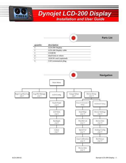
quantity description<br />
1 <strong>LCD</strong>-<strong>200</strong> Display<br />
1 <strong>LCD</strong>-<strong>200</strong> Display cable<br />
1 CD-ROM<br />
2 dual lock or velcro<br />
1 1GB SD card (optional)<br />
1 CAN termination plug<br />
Log File Manage<br />
page 5<br />
Main Menu<br />
<strong>LCD</strong> Config<br />
Touch Panel<br />
page 6<br />
<strong>LCD</strong> Info<br />
page 6<br />
Backlight<br />
page 6<br />
Colors<br />
page 7<br />
Gauge Setup<br />
page 7<br />
<strong>Power</strong> Comm<strong>and</strong>er 5<br />
Setup<br />
Send Map<br />
page 10<br />
Throttle Cal<br />
page 11<br />
Speed Cal<br />
page 11<br />
Gear Calibration<br />
page 12<br />
Device Info<br />
page 12<br />
Device Setup<br />
page 10<br />
Parts List<br />
Navigation<br />
Wideb<strong>and</strong> 2 Setup<br />
Device Settings<br />
page 13<br />
Device Info<br />
page 14<br />
Analog Config<br />
page 15<br />
Test Sensor<br />
page 17<br />
I<strong>LCD</strong>-<strong>200</strong>.02 Dynojet <strong>LCD</strong>-<strong>200</strong> Display - 1
LD016<br />
Figure 1<br />
Figure 2<br />
attach black<br />
connector<br />
USB cable<br />
memory card<br />
door<br />
<strong>Installation</strong><br />
The Dynojet <strong>LCD</strong>-<strong>200</strong> Display allows you to view real<br />
time data, log data being displayed, <strong>and</strong> store data for<br />
Dynojet products.<br />
For assistance, please contact Dynojet Technical Support<br />
at 1-800-992-4993, or email Dynojet at<br />
tech@dynojetwb2.com.<br />
1 Plug the black connector on the Display cable into the Display <strong>and</strong> the small CAN connector into the<br />
CAN communication port on the Wideb<strong>and</strong> 2.<br />
Note: For the device(s) connected to the Display, any open CAN port should have the CAN<br />
termination plug installed.<br />
2 Open the door on the side of the Display.<br />
3 Insert the memory card. The memory card is used to log <strong>and</strong> store data. Refer to “Memory Card” on<br />
page 2 <strong>and</strong> “Display File Manager” on page 18.<br />
4 To connect the Display to your computer, plug a mini-B USB cable into the Display. Plug the USB<br />
cable into your computer.<br />
Note: Although the Display is water resistant, it is NOT waterproof. Remove the Display when<br />
washing the vehicle or in heavy rain. The Display will NOT be warranted if water damage is present.<br />
Memory Card<br />
The Display supports memory cards from 128MB to 1<br />
GB. The first time you install a memory card, you may<br />
need to format it for the Display.<br />
Note: Formatting the memory card will erase all data on<br />
the memory card. If you use a memory card from your<br />
digital camera, for example, any photos on that card will<br />
be erased when formatting.<br />
1 Insert the memory card into the slot located next to the USB port on the Display. Refer to<br />
“<strong>Installation</strong>” on page 2.<br />
2 Supply power to the Display by connecting a USB cable from the Display to your computer.<br />
The SD Format screen will appear. If the SD Format screen does not appear, the memory card<br />
has already been formatted <strong>and</strong> is ready to be used with the Display.<br />
3 Touch Format to format the memory card or touch Cancel to abort the formatting process <strong>and</strong> exit<br />
the screen.<br />
If the memory card is not formatted, it will not be usable with the Display.<br />
Once formatting is complete, the Format Confirmation screen will appear.<br />
4 Touch OK in the Format Confirmation screen.<br />
The memory card is now ready to store data logging files.<br />
www.dynojetwb2.com Dynojet <strong>LCD</strong>-<strong>200</strong> Display - 2
Figure 3<br />
Figure 4<br />
Display Overview<br />
The Display is designed with touch screen capabilities.<br />
All menus <strong>and</strong> information can be accessed by touching<br />
the screen.<br />
Note: The touch screen is delicate <strong>and</strong> can be scratched<br />
or torn. Do not use sharp objects or unnecessary force.<br />
Dynojet recommends using your finger or a plastic<br />
stylus. If the screen does not respond where you touch<br />
it, calibrate the screen. Refer to “Touch Panel” on page 6<br />
for more information.<br />
In addition to the touch screen, the Display has three buttons. All menus <strong>and</strong> information can be<br />
accessed by using the buttons.<br />
• Top button—goes back one screen.<br />
• Bottom button—enters menu option.<br />
• Middle button—navigates through menus, toggles between menu buttons, moves the highlighter<br />
through a list, <strong>and</strong> moves the slider bar when selected.<br />
Gauge Screen<br />
The Gauge screen is the main screen on the Display. The<br />
Gauge screen allows you to view real time data or play<br />
back a saved log file.<br />
www.dynojetwb2.com Dynojet <strong>LCD</strong>-<strong>200</strong> Display - 3
Figure 5<br />
Figure 6<br />
Main Menu Choices<br />
Touch the Gauge screen anywhere or press any of the<br />
buttons to bring up the list of main menu choices. Each<br />
of the five main menu choices <strong>and</strong> their functions are<br />
described in more detail throughout this guide.<br />
Begin Log<br />
Begin Log allows you to begin logging information to the<br />
Display. You must have a memory card to log a file.<br />
Note: When the memory card is full, the Display will<br />
notify you. The Display will not log any new files until<br />
you erase files from the memory card. Refer to page 18.<br />
Note: Channels must be configured before you can log a<br />
file. Refer to “Log File Manage” on page 5.<br />
Refer to “Log File Manage” on page 5 for more<br />
information on how to playback log files.<br />
Refer to “Display File Manager” on page 18 for more<br />
information on downloading logs to your computer.<br />
1 Insert the memory card.<br />
2 Supply power to the Display by turning on the vehicle.<br />
3 Touch the Gauge screen or any of the buttons to bring up the menu choices.<br />
4 Touch Begin Log to start logging information.<br />
Once the log has started, you will see the message Logging Started <strong>and</strong> the gauge screen will<br />
appear.<br />
5 Touch the Gauge screen or any of the buttons to bring up the menu choices.<br />
6 Touch Stop Log to stop logging information.<br />
Once the log has stopped, you will see the message Logging Stopped <strong>and</strong> the default gauge<br />
screen will appear.<br />
Once you touch the Begin Log button, it becomes the Stop Log button.<br />
www.dynojetwb2.com Dynojet <strong>LCD</strong>-<strong>200</strong> Display - 4
Figure 7<br />
Figure 8<br />
Log File Manage<br />
Log File Management allows you to view, play back, <strong>and</strong><br />
delete log files. The naming is determined automatically<br />
by the Display starting at DisplayLog00.displog through<br />
DisplayLog99.displog. You must have a memory card to<br />
view logged files.<br />
Note: When the memory card is full, the Display will<br />
notify you. The Display will not log any new files until<br />
you send your current logged files to your computer <strong>and</strong><br />
erase files from the memory card. Refer to page 18.<br />
Note: Channels must be configured before you can log a<br />
file.<br />
1 Insert the memory card.<br />
2 Supply power to the Display by connecting the USB<br />
cable or turning on the vehicle.<br />
3 Touch the Gauge screen �Log File Manage.<br />
4 Select the log file from the list. Scroll through the list<br />
by touching the up or down arrows or use the<br />
middle button. Detailed information about the log<br />
file is displayed in the box below.<br />
Note: No log files will be displayed until you log a run.<br />
Refer to page 4.<br />
5 Touch Delete File to delete the selected file.<br />
6 Touch Play File to play the file back.<br />
The Display automatically switches to the Gauge<br />
screen <strong>and</strong> plays back the file.<br />
7 When playback is complete, a window will appear.<br />
Touch OK to exit playback.<br />
Note: If you touch the Gauge screen during playback,<br />
playback will be stopped.<br />
SETTING CHANNELS FOR LOGGING<br />
1 Touch Select Channels to select which channels<br />
will be logged.<br />
2 Select a device from the list as shown in Figure 8.<br />
Figure 9<br />
3 Touch Select All to select all the channels for that device to be logged.<br />
4 Touch Clear All to clear all the channels for that device.<br />
5 Touch Select Some to select specific channels from the highlighted device to be logged as shown in<br />
Figure 9.<br />
6 Touch Save to save your changes.<br />
Or<br />
Touch Cancel to exit the screen with no changes.<br />
7 Touch Exit to exit the Log File Management screen.<br />
www.dynojetwb2.com Dynojet <strong>LCD</strong>-<strong>200</strong> Display - 5
Figure 10<br />
Figure 11<br />
Figure 12<br />
<strong>LCD</strong> Config<br />
TOUCH PANEL<br />
Touch Panel Calibration allows you to calibrate the<br />
touch screen should it become unusable. This is done<br />
before the Display is shipped, but may need to be<br />
performed by the user in the future.<br />
Note: If the touch screen is not calibrated <strong>and</strong> unusable,<br />
use the buttons to navigate to the Touch Panel<br />
Calibration screen.<br />
1 Touch the Gauge screen �<strong>LCD</strong> Config �Touch<br />
Panel.<br />
2 Touch Start to begin calibration.<br />
3 Touch the center of each target as they appear on<br />
the screen. There are a total of five targets with the<br />
last target appearing in the middle.<br />
4 Touch OK to complete calibration.<br />
<strong>LCD</strong> INFO<br />
<strong>LCD</strong> Info allows you to view information about the <strong>LCD</strong><br />
Display.<br />
1 Touch the Gauge screen �<strong>LCD</strong> Config �<strong>LCD</strong><br />
Info.<br />
2 Touch OK to exit the screen.<br />
BACKLIGHT<br />
Backlight allows you to control the brightness of the<br />
<strong>LCD</strong> Display screen.<br />
1 Touch the Gauge screen �<strong>LCD</strong> Config<br />
�Backlight.<br />
2 Touch Less or More to change the brightness of the<br />
screen.<br />
3 Touch OK to accept the changes.<br />
www.dynojetwb2.com Dynojet <strong>LCD</strong>-<strong>200</strong> Display - 6
Figure 13<br />
Figure 14<br />
Figure 15<br />
<strong>LCD</strong> Config Continued<br />
COLORS<br />
Colors allows you to control the background, button,<br />
text, <strong>and</strong> window colors shown on the <strong>LCD</strong> Display.<br />
1 Touch the Gauge screen �<strong>LCD</strong> Config �Colors.<br />
2 Select the desired colors from the drop down lists.<br />
3 Touch OK to accept the changes<br />
OR<br />
Touch Defaults to return to the <strong>LCD</strong> Display to the<br />
default settings.<br />
Gauge Setup<br />
Gauge Setup allows you to change the layout <strong>and</strong><br />
appearance of the gauges shown on the Gauge screen.<br />
1 Touch the Gauge screen �Gauge Setup.<br />
2 Touch a Gauge Template. The current template will<br />
be outlined in yellow.<br />
3 Touch Edit to modify a gauge. Refer to the gauge<br />
attributes described below.<br />
4 Touch Exit to save the gauge attribute changes.<br />
5 Touch Exit to save the gauge setup changes.<br />
6 If you change the set up of the analog channel on<br />
the Wideb<strong>and</strong> 2, you will need to return to the<br />
Gauge Setup screen <strong>and</strong> re-select the new analog<br />
channel before it will display correctly on the Gauge<br />
screen.<br />
www.dynojetwb2.com Dynojet <strong>LCD</strong>-<strong>200</strong> Display - 7
Figure 16<br />
Figure 17<br />
Gauge Setup Continued<br />
ANALOG GAUGE SETUP<br />
• Alarm High—indicates where the red alarm section on<br />
the high range of the gauge will start.<br />
• Warn High—indicates where the yellow warning<br />
section on the high range of the gauge will start.<br />
• Alarm Low—indicates where the red alarm section on<br />
the low range of the gauge will end.<br />
• Precision—decides how many decimal places will be<br />
displayed on the gauge. For example, setting a<br />
precision of 1 means one decimal place will be shown<br />
(1.1).<br />
• Divider—divides the actual measured number in order<br />
to display it better. For example, setting a divider of<br />
1000 for RPM will display 3x1000 instead of 3000. The<br />
divider will be displayed in the lower part of the round<br />
analog gauge.<br />
• Channel—lists the current channel displayed on the<br />
gauge. Select the device from the Device Select<br />
column then select a channel from the Channel Select<br />
column. Refer to Figure 17.<br />
• Maximum/Minimum—is the maximum <strong>and</strong> minimum<br />
numbers displayed by the gauge.<br />
• Ticks—allows you to choose how many numbered tick<br />
marks are displayed by the gauge.<br />
• Face—allows you to choose the color of the gauge<br />
face.<br />
• Text—allows you to choose the color of the gauge text.<br />
• Needle—allows you to choose the color of the gauge<br />
needle.<br />
www.dynojetwb2.com Dynojet <strong>LCD</strong>-<strong>200</strong> Display - 8
Figure 18<br />
Figure 19<br />
Gauge Setup Continued<br />
DIGITAL GAUGE SETUP<br />
• Channel—lists the current channel displayed on the<br />
gauge. Select the device from the Device Select<br />
column then select a channel from the Channel Select<br />
column.<br />
• Precision—decides how many decimal places will be<br />
displayed on the gauge. For example, setting a<br />
precision of 1 means one decimal place will be shown<br />
(1.1).<br />
• Divider—divides the actual measured number in order<br />
to display it better.<br />
• Box Color—allows you to choose the background<br />
color of the gauge box.<br />
• LED Color—allows you to choose the color of the<br />
number segments.<br />
BAR GAUGE SETUP<br />
• Channel—lists the current channel displayed on the<br />
gauge. Select the device from the Device Select<br />
column then select a channel from the Channel Select<br />
column.<br />
• Maximum/Minimum—is the maximum <strong>and</strong> minimum<br />
numbers displayed by the gauge.<br />
• Divider—divides the actual measured number in order<br />
to display it better.<br />
www.dynojetwb2.com Dynojet <strong>LCD</strong>-<strong>200</strong> Display - 9
Figure 20<br />
Figure 21<br />
Device Setup<br />
Device Setup allows you to change the parameters of the<br />
different devices connected to the Display.<br />
1 Touch the Gauge screen �Device Setup.<br />
2 Select a device from the list.<br />
3 Touch Select.<br />
OR<br />
Touch Cancel to exit the screen with no changes.<br />
<strong>Power</strong> Comm<strong>and</strong>er V<br />
5 Click OK.<br />
Or<br />
Click Exit to exit the window without sending the map.<br />
6 Click Delete Map to delete the map from the list.<br />
Or<br />
Click Exit to exit the window.<br />
SEND MAP<br />
Send maps stored on the Display to a <strong>Power</strong><br />
Comm<strong>and</strong>er. You must have an SD card. The Display File<br />
Manager software allows you to move log files between<br />
the Display <strong>and</strong> your computer. Refer to “Display File<br />
Manager” on page 18 for more information.<br />
1 Touch the Gauge screen �Device Setup �<br />
PC5 Device 0 �Select �Send Map.<br />
2 Select a map from the list.<br />
3 Click Send Map.<br />
4 Click Send Map 1 to send the map to the power<br />
comm<strong>and</strong>er.<br />
www.dynojetwb2.com Dynojet <strong>LCD</strong>-<strong>200</strong> Display - 10
Figure 22<br />
Figure 23<br />
<strong>Power</strong> Comm<strong>and</strong>er V Continued<br />
THROTTLE CAL<br />
The Display can be used to calibrate the throttle<br />
position for the power comm<strong>and</strong>er.<br />
1 Touch the Gauge screen �Device Setup �<br />
PC5 Device 0 �Select �Throttle Cal.<br />
2 Verify the engine is running.<br />
3 With the throttle closed, touch Reset.<br />
4 Fully open the throttle <strong>and</strong> close it. The open<br />
throttle value will be stored.<br />
5 Touch Save to save the new calibrated numbers.<br />
Or<br />
Touch Cancel to exit the screen with no<br />
changes.<br />
SPEED CAL<br />
Speed calibration should be performed on a dyno.<br />
There are two methods for calibrating speed.<br />
SPEED CALIBRATION METHOD 1<br />
1 Touch the Gauge screen �Device Setup �<br />
PC5 Device 0 �Select �Speed Cal.<br />
2 Verify the engine is running.<br />
3 Under Target Speed, touch Edit.<br />
4 Type in a target speed.<br />
5 Hold the bike at the target speed. It does not matter<br />
which gear you are in.<br />
6 Touch At Target Speed.<br />
7 Touch Accept.<br />
Or<br />
Touch Cancel to exit the screen with no<br />
changes.<br />
SPEED CALIBRATION METHOD 2<br />
Manually type in a scalar appropriate for your bike.<br />
Check with Dynojet technical support for these values.<br />
1 Touch the Gauge screen �Device Setup �PC5<br />
Device 0 �Select �Speed Cal.<br />
2 Under Calibration Scalar, touch Edit.<br />
3 Type in a scalar appropriate for your bike.<br />
4 Touch Accept.<br />
Or<br />
Touch Cancel to exit the screen with no<br />
changes.<br />
www.dynojetwb2.com Dynojet <strong>LCD</strong>-<strong>200</strong> Display - 11
Figure 24<br />
Figure 25<br />
<strong>Power</strong> Comm<strong>and</strong>er V Continued<br />
GEAR CALIBRATION<br />
Gear calibration should be performed on a dyno.<br />
Speed calibration must be completed <strong>and</strong> you must<br />
touch Accept before proceeding with gear calibration.<br />
Refer to “Speed Cal” on page 11 for more information.<br />
1 Touch the Gauge screen �Device Setup �<br />
PC5 Device 0 �Select �Gear Calibration.<br />
2 Verify the engine is running.<br />
3 With the bike in first gear <strong>and</strong> while holding the<br />
throttle steady, touch Calibrate Target Gear for<br />
Target Gear:1.<br />
4 Touch Next Gear to moved to gear 2.<br />
5 With the bike in second gear <strong>and</strong> while holding the<br />
throttle steady, touch Calibrate Target Gear for<br />
Target Gear:2.<br />
6 Continue this process through all of the gears.<br />
7 Touch Accept to accept the changes.<br />
Or<br />
Touch Cancel to exit the screen with no<br />
changes.<br />
DEVICE INFO<br />
Device Info allows you to view the information available<br />
about the connected <strong>Power</strong> Comm<strong>and</strong>er 5 device.<br />
Touch the Gauge screen �Device Setup �<br />
PC5 Device 0 �Select �Device Info.<br />
www.dynojetwb2.com Dynojet <strong>LCD</strong>-<strong>200</strong> Display - 12
Figure 26<br />
Wideb<strong>and</strong> 2/Autotune<br />
DEVICE SETTINGS<br />
Device Settings allows you to change the device settings<br />
of the Wideb<strong>and</strong> 2. The Device Settings feature is highly<br />
configurable for many different applications <strong>and</strong> types of<br />
ignition systems. The settings described below are<br />
designed to assist you with acquiring an accurate,<br />
reliable tachometer signal. For assistance on tachometer<br />
signals, please contact Dynojet Technical Support at<br />
1-800-992-4993, or email Dynojet at<br />
tech@dynojetwb2.com.<br />
1 Touch the Gauge screen �Device Setup �WB2 Device 0 �Select �Device Settings.<br />
2 Touch Edit to modify the device settings shown on page one.<br />
Touch Less or More to change the values of these settings. These device settings are<br />
described below.<br />
3 Touch Next to advance to the next page of device settings.<br />
4 Touch Edit to modify the device settings shown on page two.<br />
Touch Less or More to change the values of these settings. These device settings are<br />
described below.<br />
5 Touch Next to advance to the next page of device settings.<br />
6 Touch the bullet next to the device settings on page three to activate that setting.<br />
These device settings are described below.<br />
7 Touch Save to save the settings.<br />
OR<br />
Touch Cancel to exit the screen with no changes.<br />
• Display Update Rate (range = 1 - 20, default value = 20)—changes the update rate of the gauges,<br />
where 1 is the slowest update rate <strong>and</strong> 20 is the quickest update rate.<br />
• Lambda Smoothing (range = 1 - 255, default value = 10)—smooths, or averages, the AFR <strong>and</strong> Lambda<br />
channels. Lower values will result in the highest resolution, minimal latency, <strong>and</strong> would be preferred in<br />
situation where you are datalogging. This setting smooths/averages all AFR/Lambda output signals,<br />
including the gauge <strong>and</strong> 0-5v channels.<br />
• Stoichiometric AFR (range = 0 - ambient, default value = 14.7)—sets the stoichiometric air/fuel value<br />
for the measured Lambda. Use 14.7 for gasoline. For assistance on other fuels besides gasoline, please<br />
contact Dynojet Technical Support at 1-800-992-4993, or email Dynojet at tech@dynojetwb2.com.<br />
• O2 Out Threshold (range = .9 -1.1, default value = 1)—sets up the Narrowb<strong>and</strong> O2 Out function on<br />
the Wideb<strong>and</strong> 2 (green wire). Changing this value will change the AFR that Wideb<strong>and</strong> 2 switches the<br />
narrowb<strong>and</strong> signal around. For example, if using a value of .95, the Wideb<strong>and</strong> 2 will emulate a<br />
narrowb<strong>and</strong> voltage signal that switches to rich if the Lambda reading is lower than .95, <strong>and</strong> lean if the<br />
Lambda reading is higher than .95. In most cases, you will not be using the "Narrowb<strong>and</strong> O2 Out<br />
function", but if you do, please contact Dynojet Technical Support at 1-800-992-4993, or email Dynojet<br />
at tech@dynojetwb2.com. This setting is for Wideb<strong>and</strong> 2 only.<br />
• Tach Signal (range = 1 - 16, default value = 1)—adjusts the RPM multiplier used for the RPM input on<br />
the Wideb<strong>and</strong> 2. In order to acquire an accurate tach signal reading, you will need to adjust this setting<br />
for your application. This setting is for Wideb<strong>and</strong> 2 only.<br />
www.dynojetwb2.com Dynojet <strong>LCD</strong>-<strong>200</strong> Display - 13
Wideb<strong>and</strong> 2/Autotune Continued<br />
DEVICE SETTINGS CONTINUED<br />
• Tach Smoothing (range = 1 - 16, default value = 2)—smooths the RPM input signal of the Wideb<strong>and</strong> 2.<br />
This setting is useful to stabilize, or dampen the RPM signal displayed on the <strong>LCD</strong>. This setting is for<br />
Wideb<strong>and</strong> 2 only.<br />
• Tach Signal Filter (range = 1 - 255, default value = 30)—filters out invalid RPM signal inputs. This<br />
setting can be adjusted if you notice the tach reading displayed on the <strong>LCD</strong> is unstable, spiking, or<br />
otherwise inconsistent. This setting is for Wideb<strong>and</strong> 2 only.<br />
The following settings are useful for vehicles that have a CDI (capacitive discharge ignitions) system, or<br />
on applications that require additional flexibility when setting up the tachometer input.<br />
• Attenuate Tach Signal (setting is either active or inactive)—makes the RPM input signal smaller (less<br />
voltage) to filter out noise. This setting is for Wideb<strong>and</strong> 2 only.<br />
Note: This setting should be off in most automotive applications that are using the PCM’s tach output<br />
or the (-) side of the coil as a tach input.<br />
• Bias Tach Signal (setting is either active or inactive)—will bias the entire RPM signal input to a higher<br />
voltage. The ability to activate this feature only appears when "Attenuate Tach Signal" is selected. This<br />
setting is for Wideb<strong>and</strong> 2 only.<br />
• Rising Edge (setting is either active or inactive)—allows the Wideb<strong>and</strong> 2 to measure the rising edge on<br />
the RPM voltage signal. This setting is for Wideb<strong>and</strong> 2 only.<br />
Note: This setting should be off in most automotive applications that are using the PCM’s tach output<br />
or the (-) side of the coil as a tach input.<br />
Figure 27<br />
DEVICE INFO<br />
Device Info allows you to view the information available<br />
about the connected Wideb<strong>and</strong> 2 device.<br />
Touch the Gauge screen �Device Setup �<br />
WB2 Device 0 �Select �Device Info.<br />
www.dynojetwb2.com Dynojet <strong>LCD</strong>-<strong>200</strong> Display - 14
Figure 28<br />
Figure 29<br />
Wideb<strong>and</strong>2/Autotune Continued<br />
ANALOG CONFIG<br />
Analog Channel Calibration allows you to calibrate the<br />
throttle position to the current bike or change the analog<br />
input for a 0-5v sensor other than a throttle position<br />
sensor.<br />
ANALOG CONFIG—THROTTLE POSITION<br />
1 Touch the Gauge screen �Device Setup �<br />
WB2 Device 0 �Select �Analog Config.<br />
2 Select Throttle Position.<br />
3 Touch Throttle Cal.<br />
4 Close the throttle to set the closed position. This is<br />
indicated by the number shown under "closed" <strong>and</strong><br />
where the green bar starts.<br />
5 Touch Reset.<br />
6 Open the throttle all the way to set the open<br />
position. This is indicated by the number shown<br />
under "open" <strong>and</strong> where the green bar ends.<br />
Note: This should be done with the vehicle running.<br />
7 Touch Save to accept the throttle calibration.<br />
OR<br />
Touch Cancel to exit the screen with no changes.<br />
www.dynojetwb2.com Dynojet <strong>LCD</strong>-<strong>200</strong> Display - 15
Figure 30<br />
Figure 31<br />
Wideb<strong>and</strong> 2/Autotune Continued<br />
ANALOG CONFIG—USER DEFINED<br />
1 Touch the Gauge screen �Device Setup �<br />
WB2 Device 0 �Select �Analog Config.<br />
2 Select <strong>User</strong> Defined.<br />
3 Touch Setup Channel.<br />
4 Touch Edit to modify the channel names <strong>and</strong> units.<br />
Change the value using the alphanumeric keypad.<br />
This keypad works like a cell phone keypad.<br />
• BS—backspace.<br />
• C—clear. Clears the entire displayed number.<br />
• CAN—cancel. Closes the keypad window without<br />
making any changes.<br />
• OK—changes the number setting <strong>and</strong> closes the<br />
keypad window.<br />
5 Touch Transfer Function.<br />
6 Touch the upper left button <strong>and</strong> use the number pad<br />
to enter a voltage for the transfer function of the<br />
sensor. For example, enter 1.00V (Figure 31).<br />
7 Touch the adjacent button to the right <strong>and</strong> enter the<br />
actual value that corresponds to the voltage entered<br />
in step #6. For example, enter 20%.<br />
This will tell the <strong>LCD</strong>-<strong>200</strong> to display 1.00V as 20%.<br />
The displayed value is determined when you modify<br />
the channel names <strong>and</strong> units in step #4.<br />
8 Use the same procedure for the other transfer<br />
function buttons.<br />
Once all the buttons have been configured with the proper transfer function, the <strong>LCD</strong> will<br />
have enough information to display the 0-5v analog input as a usable number.<br />
9 Touch OK to save the transfer function.<br />
Or<br />
Touch Cancel to exit the screen with no changes <strong>and</strong> return to the Setup Analog Channel<br />
screen.<br />
10 Touch Save to save the configuration.<br />
Or<br />
Touch Cancel to exit the screen with no changes <strong>and</strong> return to the Analog Channel<br />
Configuration screen.<br />
11 Touch Save to save the configuration.<br />
Or<br />
Touch Cancel to exit the screen with no changes <strong>and</strong> return to the Wideb<strong>and</strong> 2 Setup screen.<br />
12 Touch Exit to return to the Main Menu.<br />
13 Touch Gauge Setup.<br />
14 Select which gauges you would like to display the user defined channel <strong>and</strong> how you would like the<br />
gauge to look. Refer to “Gauge Setup” on page 7 for more information.<br />
www.dynojetwb2.com Dynojet <strong>LCD</strong>-<strong>200</strong> Display - 16
Figure 32<br />
ELEVATION (in feet)<br />
8000<br />
7000<br />
6000<br />
5000<br />
4000<br />
3000<br />
<strong>200</strong>0<br />
1000<br />
Figure 33<br />
0<br />
0<br />
1<br />
sensor ok<br />
2 3 4 5 6 7 8<br />
FLASHES<br />
Wideb<strong>and</strong> 2/Autotune Continued<br />
9 10<br />
TEST SENSOR<br />
Test Sensor allows you to test the O2 sensor <strong>and</strong> verify<br />
the sensor is working properly.<br />
Note: Disconnect the O2 sensor from the exhaust pipe<br />
while doing this test.<br />
1 Touch the Gauge screen �Device Setup �<br />
WB2 Device 0 �Select �Test Sensor.<br />
2 Verify the sensor is connected properly <strong>and</strong> the<br />
Sensor Condition reads Sensor Ready.<br />
Note: A cold sensor requires ten to twenty seconds to<br />
heat up.<br />
3 Touch Start Test.<br />
4 Wave the O2 Sensor in clean ambient air.<br />
Note: It is important to disconnect the O2 sensor from<br />
the exhaust pipe while doing this test.<br />
5 Read the Sensor Condition Number shown on the <strong>LCD</strong> Display screen. You may also count the<br />
number of long blinks on the Wideb<strong>and</strong> 2.<br />
6 Using the Sensor Condition Chart shown above, verify the sensor is within the working range.<br />
If the sensor is out of the range shown on the chart, the Wideb<strong>and</strong> 2 will show quick<br />
continuous blinks <strong>and</strong> the Display will read "xxx". This indicates a bad sensor. Turn the power<br />
off <strong>and</strong> replace the sensor before continuing.<br />
7 Touch Exit to exit the screen.<br />
www.dynojetwb2.com Dynojet <strong>LCD</strong>-<strong>200</strong> Display - 17
Figure 34<br />
INSTALLING THE DISPLAY FILE MANAGER SOFTWARE<br />
Display File Manager<br />
The Display File Manager software allows you to<br />
move log files between the Display <strong>and</strong> your<br />
computer. The main interface contains a set of tabs,<br />
Maps <strong>and</strong> Logs. These tabs display the files that exist<br />
on the memory card in the corresponding directory.<br />
The main interface has five buttons which are also<br />
accessible from the Actions menu. The main interface<br />
buttons <strong>and</strong> menu items are described below.<br />
1 Insert the CD, included with the Display, in your CD-ROM drive. The launch program will run<br />
automatically.<br />
Note: This software may also be downloaded at www.powercom<strong>and</strong>er.com.<br />
2 Click <strong>LCD</strong> File Manager Software.<br />
3 Follow the on-screen instructions.<br />
4 Connect the Display to your computer using the USB cable.<br />
USING THE DISPLAY FILE MANAGER SOFTWARE<br />
Data logging files have a .displog file extension. This is raw data. The Display File Manager converts these<br />
files into a format viewable in Excel with a .csv file extension.<br />
Click Options �Log File Export Options to set up the time interval between data samples for the .csv<br />
files created from data logging files. The default 1.0 will put one second between each line in the .csv file.<br />
Choose a value from the drop down list or type any valid real number directly into the field. By default,<br />
the software will automatically create .csv files for any logs pulled from the device. This can be disabled by<br />
deselecting Auto Convert Log Files.<br />
Click Actions �Update Firmware to update the Display firmware. Update Firmware will only be<br />
enabled when the Display is in bootloader mode.<br />
Note: Updating the firmware is not necessary unless Dynojet has prompted you to do so.<br />
• To enter bootloader you must have the three buttons on the Display depressed while you<br />
connect the USB to the Display. Once in bootloader mode, a blue screen with some basic<br />
device information is displayed.<br />
• Click the Actions drop down menu in the Display File Manager software. Click Update<br />
Firmware.<br />
• Find the desired firmware file (.djf) on your computer. The software will prepare the<br />
Display for the new firmware to send the file to it. A progress indicator will be displayed<br />
during this process. After a successful reprogram the software will start the new Display<br />
firmware automatically. Resume normal software operation.<br />
www.dynojetwb2.com Dynojet <strong>LCD</strong>-<strong>200</strong> Display - 18
Figure 35<br />
Display File Manager Continued<br />
USING THE MAIN INTERFACE BUTTONS<br />
A detailed description of the main interface buttons<br />
(also found under the Action menu) follows.<br />
Click Convert Log Files To .csv to select Display log files that already exist on your computer (not the<br />
Display) <strong>and</strong> convert them to an Excel compatible format for advanced analysis. These files will be<br />
created in the same directory <strong>and</strong> have the same name as your .displog files but with a new .csv<br />
extension.<br />
Click Show Device Info to display a dialog that outlines the build information for the Display. This<br />
button is only available when the Display is connected to the USB port on the computer.<br />
Click Get Selected Files to pull files from the memory card in the Display <strong>and</strong> save them on your<br />
computer. Enter a destination for the files. A progress indicator will be displayed during this process. This<br />
button is only available when the Display is connected to the USB port on the computer.<br />
Click Send Files to Device to put files on the memory card in the Display. You will be prompted for the<br />
appropriate type of files based on the current tab selected, Maps or Logs. Any files selected in the dialog<br />
will be pushed to the Display <strong>and</strong> a progress indicator will be displayed. You can drag files from any<br />
Explorer window on to the file lists on the main interface. Files that match the appropriate extension for<br />
the active tab .djm <strong>and</strong> .displog will be sent to the memory card immediately. Dragging directories <strong>and</strong><br />
invalid files is not supported. This button is only available when the Display is connected to the USB port<br />
on the computer.<br />
Click Delete Selected Files to delete files off the memory card in the Display. No confirmation dialog is<br />
displayed <strong>and</strong> no undo is possible. Any files that are selected in the list will be immediately removed from<br />
the card. This button is only available when the Display is connected to the USB port of the computer.<br />
www.dynojetwb2.com Dynojet <strong>LCD</strong>-<strong>200</strong> Display - 19