Implementing Complex Motor Control Algorithms with a ... - Infineon
Implementing Complex Motor Control Algorithms with a ... - Infineon
Implementing Complex Motor Control Algorithms with a ... - Infineon

Create successful ePaper yourself
Turn your PDF publications into a flip-book with our unique Google optimized e-Paper software.
And once the calculations have been completed, the results need to be<br />
scaled and transferred to output peripherals. The synchronization of all of<br />
the input/output functions is just as critical as the ability to perform the<br />
high level calculations.<br />
Using an additional CPU to schedule and read ADC results, setup PWM<br />
values, read and filter sensor inputs, etc., can be very helpful. However<br />
there are also many disadvantages in using a separate asymmetric core.<br />
Extra effort is required to determine the best way to partition and synchronize<br />
the tasks between the cores for example. More time is required to<br />
learn the additional instruction set, architecture quirks and tool-chain for<br />
the additional core. When all of that work is finished, almost none of it is<br />
portable to MCUs from another supplier.<br />
Even though the tasks performed by the<br />
additional core are usually quite simple,<br />
those tasks must be performed <strong>with</strong> hard,<br />
real-time constraints. Using a single core<br />
would clearly be beneficial, but meeting<br />
the real-time requirements while performing<br />
the higher level algorithms and responding<br />
to the user interface can be a challenge,<br />
even for a Cortex-M4 core.<br />
Most of the additional tasks the second<br />
CPU would be used for consist of moving<br />
data and synchronizing I/O events. These<br />
tasks can equally be accomplished by<br />
smart peripherals linked together via a<br />
flexible connection matrix.<br />
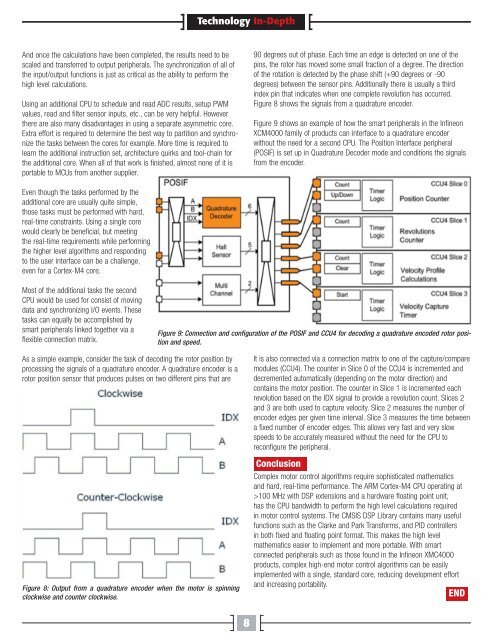
As a simple example, consider the task of decoding the rotor position by<br />
processing the signals of a quadrature encoder. A quadrature encoder is a<br />
rotor position sensor that produces pulses on two different pins that are<br />
Figure 8: Output from a quadrature encoder when the motor is spinning<br />
clockwise and counter clockwise.<br />
Technology In-Depth<br />
8<br />
90 degrees out of phase. Each time an edge is detected on one of the<br />
pins, the rotor has moved some small fraction of a degree. The direction<br />
of the rotation is detected by the phase shift (+90 degrees or -90<br />
degrees) between the sensor pins. Additionally there is usually a third<br />
index pin that indicates when one complete revolution has occurred.<br />
Figure 8 shows the signals from a quadrature encoder.<br />
Figure 9 shows an example of how the smart peripherals in the <strong>Infineon</strong><br />
XCM4000 family of products can interface to a quadrature encoder<br />
<strong>with</strong>out the need for a second CPU. The Position Interface peripheral<br />
(POSIF) is set up in Quadrature Decoder mode and conditions the signals<br />
from the encoder.<br />
Figure 9: Connection and configuration of the POSIF and CCU4 for decoding a quadrature encoded rotor position<br />
and speed.<br />
It is also connected via a connection matrix to one of the capture/compare<br />
modules (CCU4). The counter in Slice 0 of the CCU4 is incremented and<br />
decremented automatically (depending on the motor direction) and<br />
contains the motor position. The counter in Slice 1 is incremented each<br />
revolution based on the IDX signal to provide a revolution count. Slices 2<br />
and 3 are both used to capture velocity. Slice 2 measures the number of<br />
encoder edges per given time interval. Slice 3 measures the time between<br />
a fixed number of encoder edges. This allows very fast and very slow<br />
speeds to be accurately measured <strong>with</strong>out the need for the CPU to<br />
reconfigure the peripheral.<br />
Conclusion<br />
<strong>Complex</strong> motor control algorithms require sophisticated mathematics<br />
and hard, real-time performance. The ARM Cortex-M4 CPU operating at<br />
>100 MHz <strong>with</strong> DSP extensions and a hardware floating point unit,<br />
has the CPU bandwidth to perform the high level calculations required<br />
in motor control systems. The CMSIS DSP Library contains many useful<br />
functions such as the Clarke and Park Transforms, and PID controllers<br />
in both fixed and floating point format. This makes the high level<br />
mathematics easier to implement and more portable. With smart<br />
connected peripherals such as those found in the <strong>Infineon</strong> XMC4000<br />
products, complex high-end motor control algorithms can be easily<br />
implemented <strong>with</strong> a single, standard core, reducing development effort<br />
and increasing portability.<br />
END