Implementing Complex Motor Control Algorithms with a ... - Infineon
Implementing Complex Motor Control Algorithms with a ... - Infineon
Implementing Complex Motor Control Algorithms with a ... - Infineon

You also want an ePaper? Increase the reach of your titles
YUMPU automatically turns print PDFs into web optimized ePapers that Google loves.
Technology In-Depth<br />
<strong>Implementing</strong> <strong>Complex</strong><br />
<strong>Motor</strong> <strong>Control</strong> <strong>Algorithms</strong><br />
<strong>with</strong> a Standard ARM ®<br />
Processor Core<br />
By Mike Copeland, Senior Staff Applications Engineer, <strong>Infineon</strong> Technologies<br />
I<br />
n the real-time MCU world, cost-effective complex motor control<br />
designs have been dominated by specialized cores. In many cases<br />
dual-core systems have been used, <strong>with</strong> the main core handling the<br />
control algorithm and a second “mini” core managing the real-time I/O<br />
and data manipulation.<br />
1
This article describes how complex motor control algorithms can be<br />
implemented easily and straight forward using MCUs that contain a single<br />
Cortex-M4 core, when used in combination <strong>with</strong> smart connected<br />
peripherals such as those found in the new <strong>Infineon</strong> XMC4000 family<br />
of products.<br />
As an example, we will look at the equations involved in Field Oriented<br />
<strong>Control</strong> (FOC) of a Permanent Magnet Synchronous <strong>Motor</strong> (PMSM), and<br />
show how they can be handled using the CMSIS DSP Library. The same<br />
principles used in this example can be applied to other control algorithms<br />
and other motor types. We will see how smart peripherals eliminate the<br />
need for a second core, and describe some of the many benefits of using<br />
a single industry standard core <strong>with</strong> the CMSIS DSP Library.<br />
PMSM Structure and Operation<br />
Before we look at the control algorithms and equations, it is important to<br />
understand the structure and operation of an PMSM.<br />
A simple three-phase PMSM consists of a permanent magnet rotor and a<br />
stationary stator <strong>with</strong> three sinusoidally distributed windings. Figure 1<br />
shows a cross-section of a simple PMSM (Yes, it did me take a long time<br />
to draw all of those circles!)<br />
(A) (B)<br />
Figure 1: Cross-section of a basic PMSM <strong>with</strong> a two pole rotor and a single<br />
stator winding (A), and the complete three-phase windings separated by 120<br />
degrees (B). The stator windings are distributed sinusoidally. Circles <strong>with</strong> a<br />
dot or an X in the middle represent wires directed out of or into (respectively)<br />
the page.<br />
The sinusoidally distributed windings in the stator are similar to what<br />
would be found in a three-phase induction motor. In single phase (e.g.<br />
phase A) the number of turns of wire at any angle (α) is approximately N S<br />
cos(α). The other two phases are identical, but shifted 120 degrees. In<br />
reality, the windings are only approximately sinusoidally distributed.<br />
Fortunately for FOC, close is good enough.<br />
As Mr. Tesla discovered, if you apply three-phase sinusoidal currents to<br />
this type of stator, a rotating sinusoidally distributed flux is created. We<br />
can prove this mathematically. The flux generated by a winding is proportional<br />
to the current through the winding and the number of coils in the<br />
winding. So by multiplying the number of coils by the current in that<br />
phase, we get an indication of the flux generated by that stator phase.<br />
This is called the Magnetomotive Force (MMF). When combined <strong>with</strong> the<br />
result from the other two phases, we get the total flux in the stator. Then,<br />
find a high school student and ask him or her to use the “Law of Cosines”<br />
to reduce the long equation into a simple one, as shown below.<br />
Technology In-Depth<br />
2<br />
To efficiently control the motor the goal is to produce stator flux that is<br />
90 degrees out of phase <strong>with</strong> the rotor flux. The torque of the motor is<br />
then proportional to the amplitude of the stator flux.<br />
Simplified FOC Theory<br />
Several years ago I worked on an MCU-based Uninterruptable Power<br />
Supply (UPS) project. I used the MCU <strong>with</strong> an integrated ADC and PWM<br />
module connected to a half bridge and a transformer to generate<br />
sinusoidal voltages. The output voltage was supposed to be a clean 110V<br />
60 Hz sinusoid independent of the load. To generate the PWM values,<br />
I first used a simple PI controller <strong>with</strong> a 110V 60 Hz reference signal. The<br />
intention was to read the actual voltage via an ADC channel and compare<br />
it to the desired voltage, feed the error into a PI controller and use the<br />
output to control the PWM value. Unfortunately this did not work very<br />
well and I nearly fried the board before I had to give up.<br />
I thought about implementing a complex non-linear control law instead of<br />
a PI controller. Non-linear control was not one of my strengths in college,<br />
so I decided to look for an easier solution. I created a look-up table of<br />
sinusoidal PWM values and stored it in the MCU memory. Once every<br />
PWM interrupt, I incremented the index into the look-up table and copied<br />
the value into the PWM register. This produced a nice 60 Hz sinusoidal<br />
signal, but it was very dependent on the load. To control the amplitude of<br />
this sinusoidal voltage, I multiplied the values from the look-up table by a<br />
scale factor before transferring them to the PWM register. Then I used a<br />
simple PI controller to control the scale factor. This worked much better.<br />
With some trigonometry (in this case just a simple sin( ) calculation via<br />
a lookup table), the simple PI controller could work just on the magnitude<br />
of the voltage which was approximately DC.<br />
FOC works on a similar principle. Remove the sinusoidal properties of the<br />
system <strong>with</strong> trigonometry, then apply simple linear PI controllers on the<br />
amplitudes.<br />
To see how this works, let’s simplify the drawing of Figure 1(B) by using<br />
vectors. Figure 2 is similar to Figure 1, except all of those little circles that<br />
were so difficult to draw are replaced by the a, b and c axes. Current<br />
flowing through phase “a” (the winding that was drawn in dark blue in<br />
Figure 1) can be represented as a vector on the “a” axis (ia). The same is<br />
true for phases b (the red winding) and c (the green winding).<br />
(A) (B)<br />
Figure 2: (A) Vector representation of the three-phase PMSM showing the<br />
three-phase currents (ia, ib, ic) and their vector sum (is). In (B) the rotor is also<br />
shown <strong>with</strong> its flux oriented around the spinning “d” axis. For maximum efficiency,<br />
is must be aligned <strong>with</strong> the rotor quadrature (q) axis.
Technology In-Depth<br />
DAVE 3 – <strong>Infineon</strong>’s Free Tool-Chain for XMC4000 MCUs,<br />
<strong>with</strong> DAVE Apps for Component-Based Programming<br />
DAVE 3 is a free tool-chain for <strong>Infineon</strong>’s new XMC4000<br />
family of ARM ® Cortex-M4 microcontrollers. Built on<br />
the Eclipse platform, DAVE 3 includes the GCC ARM ®<br />
embedded compiler/assembler/linker-locator, and a<br />
hardware debugger.<br />
There are no code size or time restrictions <strong>with</strong> DAVE 3, and a code generator<br />
(DAVE 3 CE) is included to support component-based programming via<br />
DAVE Apps.<br />
DAVE 3, DAVE 3 CE and DAVE Apps are all, 100% free.<br />
Eclipse-Based Integrated Development Environment (IDE)<br />
The open source Eclipse IDE has become a standard among embedded developers.<br />
Many MCUs are supported via an Eclipse-based IDE provided either by<br />
a third party tool supplier or by the silicon vendor themselves. An Eclipse plugin<br />
from one supplier can be inserted into the Eclipse environment from another,<br />
so DAVE 3 can utilize plug-ins from other tool suppliers and vice versa.<br />
The DAVE Eclipse platform includes plug-ins for:<br />
• GCC ARM embedded compiler (maintained by ARM)<br />
• A hardware debugger and simulator. The debugger uses the <strong>Infineon</strong><br />
DAP MiniWiggler or SEGGER J-Link as the HW interface and includes all<br />
the typical debugger features, such as a flash programmer, HW break<br />
points and single stepping.<br />
• DAVE CE for code generation<br />
• X-Spy for transmitting and receiving MCU data via a virtual COM. X-Spy<br />
allows you to create your own GUI to interact <strong>with</strong> your target hardware<br />
<strong>with</strong>out any PC side programming. X-Spy also includes an oscilloscope<br />
feature.<br />
Component-Based Programming and DAVE Apps<br />
In component-based programming, software is partitioned according to<br />
functionality. Programmers often do this partitioning naturally <strong>with</strong>out<br />
even noticing. The DAVE 3 logo, of a head comprised of small boxes<br />
(components), illustrates this principle.<br />
DAVE Apps are used to create software components for specific functions.<br />
Features include:<br />
• Optional Graphical User Interface (UI) to configure the DAVE App.<br />
• API <strong>with</strong> initialization and run-time functions. (All source code is included).<br />
• Documentation and example App API use.<br />
• Interconnection between DAVE Apps via “virtual signals”. Virtual<br />
signals represent the connection matrix that connects XMC4000<br />
peripherals to each other and to I/O pins.<br />
• Apps can be written to consume specific pieces of hardware (e.g.<br />
CCU40_Slice1, ADC0_Channel6), or can be written to use a generic<br />
hardware resource (e.g. any CCU4 slice, any ADC channel). The user is<br />
then free to constrain the DAVE App to use specific resources as<br />
required (e.g. use Port 3 Pin 9 for PWM output, use Port 14 Pin 1 for<br />
ADC input). The integrated “Solver” will then choose resources that are<br />
not constrained.<br />
• Apps can be used to generate low level drivers for specific peripherals<br />
(similar to DAVE 2), or they can be used to generate and configure<br />
complex SW components such as an RTOS or file system.<br />
3<br />
As an example, let’s look at an application that needs to produce some<br />
PWM signal and store data on an SD card. In DAVE 3 this type of<br />
application can be built in minutes using the DAVE Apps.<br />
• Double clicking the PWM App (PWMSP001) in the App Selection View<br />
window automatically inserts the PWM App and any other DAVE Apps<br />
that are required (the Clock App, Reset App, I/O App and Debug App).<br />
• Double clicking the SDMMC App (SDMMC001) adds the SDMMC App and<br />
its required Apps (SDMMC low level driver App, Clock App, Reset App and<br />
Debug App).<br />
• A FAT32 files system can be added if required by simply double clicking on<br />
the App (FATFS002).<br />
Once the Apps are inserted into the project they can be individually configured<br />
via their UIs as shown in the center window for the PWM App. Additionally, the<br />
“Pin Configurator” can be used to specify exactly which pins are used for WM<br />
and SDMMC, if required. Any constraints not specified (e.g. which CCU4 slice<br />
or which I/O pins are used) can be automatically selected via the Solver. The<br />
Solver is a key feature of DAVE 3. The user develops their application<br />
based on the functionality that they need, but then the Solver handles the task<br />
of mapping that functionality to the actual hardware.<br />
In our example PWM and SDMMC application, we can easily continue to add<br />
more features by including more DAVE Apps. To add additional PWM<br />
channels for example, simply double-click on the PWM App again and a new<br />
instance of the App is inserted. The App source code is not duplicated, but a<br />
new handle is created to use when calling the API.<br />
The code generated by DAVE Apps in DAVE 3 is included in the project<br />
and is freely available for modification, as are the templates used to generate<br />
the source code based on the UI settings. So if there is something you would<br />
like to change in an App, you can easily do so.<br />
The Future of DAVE 3<br />
DAVE 3 continues to grow as <strong>Infineon</strong> constantly adds Apps for the<br />
XCM4000. In the long term, to further increase the number of available Apps,<br />
<strong>Infineon</strong> plans to release a DAVE 3 SDK to allow anyone to create their<br />
own Apps. It is then the developer’s choice to decide whether to keep the<br />
App confidential, sell it via an on-line store, or make it freely available to the<br />
wider community.<br />
DAVE 3 can be downloaded for free from the <strong>Infineon</strong> website:<br />
www.infineon.com END
Technology In-Depth<br />
XMC4000 – <strong>Infineon</strong>’s New ARM ® Cortex -M4 Based<br />
MCUs for Communication and <strong>Control</strong><br />
Designed to meet the challenges of industrial and power conversion applications,<br />
<strong>Infineon</strong>’s new XMC4000 family features the industry standard ARM ®<br />
Cortex-M4 core, industry standard communication peripherals and state of<br />
the art real-time control peripherals.<br />
In addition to the communication peripherals normally resident on Cortex-M4<br />
MCUs such as Ethernet, USB and CAN, <strong>Infineon</strong> expands the range of Cortex-M4<br />
applications by adding the latest high performance smart peripherals for<br />
real-time control and power conversion, including motor control.<br />
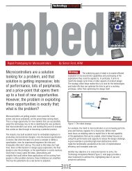
The integrated, programmable, 4-channel Delta Sigma Demodulator (DSD)<br />
reduces system complexity and allows easy connection and isolation of external<br />
Sigma Delta analog front ends. This, combined <strong>with</strong> the internal resolver<br />
exciter, makes the XCM4000 family a must have for any resolver motor application<br />
by dramatically reducing system costs (see Figure 1).<br />
Figure 1: 4 Channel Delta Sigma Demodulator (DSD) <strong>with</strong> resolver carrier<br />
pattern generator used for motor position and current measurement in<br />
a high-end motor drive.<br />
The advanced input capture/output compare peripherals (CAPCOM4 and<br />
CAPCOM8) are ideal for power conversion, motor drives and general purpose<br />
use. They include features such as dithering and floating prescalers to reduce<br />
EMI. Advance output patterns such as phase shifting and asymmetric or<br />
symmetric PWM are easily generated.<br />
In addition to the 4-channel DSD, up to four separate 8-channel, 12-bit ADCs<br />
(successive approximation) are available, <strong>with</strong> below 1 µsec conversion time,<br />
integrated limit checking, fast compare mode, integrated diagnostics and<br />
advanced trigger scheduling all included. Powerful result handling features<br />
such as automatic data reduction or averaging, and programmable FIR/IIR<br />
filtering, are also handled by the ADC.<br />
But the real power of the XMC4000 family comes from the flexible connections<br />
between the peripherals. This “connection matrix” allows complex tasks<br />
to be performed <strong>with</strong> minimal CPU intervention. For example, PWM generated<br />
by the CAPCOM4 or CAPCOM8 can temporarily disable the integrators in the<br />
Delta Sigma Demodulator for a programmable amount of time to eliminate<br />
switching noise from the analog conversion.<br />
The XMC4000 family of products provides a complete solution for designs<br />
that need both communication and control.<br />
5<br />
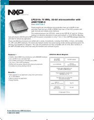
The XMC4500 is the first device in<br />
the XMC4000 family:<br />
XMC4500 System Features<br />
• ARM Cortex-M4, 120 MHz,<br />
including single cycle DSP MAC and<br />
floating point unit (FPU)<br />
• 1 MB eFlash including hardware ECC<br />
• 160 kB RAM<br />
• 12-channel DMA<br />
• Battery-backed real-time (RTC)<br />
• Flexible Connection Matrix for mapping internal/external events to pins and<br />
peripherals<br />
• Extended temperature range up to 125°C<br />
XMC4500 Communication/HMI Peripherals<br />
• IEEE 1588 compliant Ethernet MAC<br />
• USB 2.0 full-speed on-the-go<br />
• 6-channel multifunction serial interface modules<br />
(configurable to standard SPI, Dual SPI, Quad SPI, I2C, I2S, UART)<br />
• 3x CAN nodes<br />
• SD/MMC interface<br />
• Touch interface and LED Matrix<br />
• External bus interface supporting SDRAM, SRAM, NOR-/NAND-Flash and<br />
memory-mapped IO devices (e.g., LCD)<br />
• Flexible CRC Engine (FCE)<br />
XMC4500 <strong>Control</strong> Peripherals<br />
• Capture/Compare Peripherals each <strong>with</strong> 4x Edge/Center aligned Timer/<br />
Counters, Dither, Low Pass Filter, Concatenation, Trap and other features<br />
• 4x 4-Channel CAPCOM4 modules<br />
• 2x 8-Channel CAPCOM8 modules<br />
• 4x Delta-Sigma Demodulator (DSD) and Resolver Excitation<br />
• 2x Rotary Position Interface (POSIF)<br />
• 4x 8-channel 12-bit ADCs<br />
• 2x 12-bit DAC<br />
• Die Temperature Sensor (DTS)<br />
Figure 2: XMC4000 roadmap<br />
END
Technology In-Depth<br />
The Hexagon Application Kit for the XMC4000 Family<br />
The Hexagon Application Kit is a versatile new tool for the XMC4000 family. At<br />
the heart of this development platform is the CPU board <strong>with</strong> the new<br />
XMC4500 microcontroller. Kit functionality can be expanded to suit specific<br />
applications by means of satellite cards. The actuator satellite, for example,<br />
provides an extensive range of motor control functions thanks to its resolver<br />
circuit, encoder interface and shunt current sensing. The human machine<br />
7<br />
interface (HMI) board comes <strong>with</strong> an OLED display plus audio, touch and<br />
SD/MMC functions. The communication satellite enables developers to<br />
implement remote control via Ethernet. This board also supports MultiCAN<br />
and RS485 interfaces. In addition to these three satellites, developers can<br />
also connect their own boards.<br />
END
And once the calculations have been completed, the results need to be<br />
scaled and transferred to output peripherals. The synchronization of all of<br />
the input/output functions is just as critical as the ability to perform the<br />
high level calculations.<br />
Using an additional CPU to schedule and read ADC results, setup PWM<br />
values, read and filter sensor inputs, etc., can be very helpful. However<br />
there are also many disadvantages in using a separate asymmetric core.<br />
Extra effort is required to determine the best way to partition and synchronize<br />
the tasks between the cores for example. More time is required to<br />
learn the additional instruction set, architecture quirks and tool-chain for<br />
the additional core. When all of that work is finished, almost none of it is<br />
portable to MCUs from another supplier.<br />
Even though the tasks performed by the<br />
additional core are usually quite simple,<br />
those tasks must be performed <strong>with</strong> hard,<br />
real-time constraints. Using a single core<br />
would clearly be beneficial, but meeting<br />
the real-time requirements while performing<br />
the higher level algorithms and responding<br />
to the user interface can be a challenge,<br />
even for a Cortex-M4 core.<br />
Most of the additional tasks the second<br />
CPU would be used for consist of moving<br />
data and synchronizing I/O events. These<br />
tasks can equally be accomplished by<br />
smart peripherals linked together via a<br />
flexible connection matrix.<br />
As a simple example, consider the task of decoding the rotor position by<br />
processing the signals of a quadrature encoder. A quadrature encoder is a<br />
rotor position sensor that produces pulses on two different pins that are<br />
Figure 8: Output from a quadrature encoder when the motor is spinning<br />
clockwise and counter clockwise.<br />
Technology In-Depth<br />
8<br />
90 degrees out of phase. Each time an edge is detected on one of the<br />
pins, the rotor has moved some small fraction of a degree. The direction<br />
of the rotation is detected by the phase shift (+90 degrees or -90<br />
degrees) between the sensor pins. Additionally there is usually a third<br />
index pin that indicates when one complete revolution has occurred.<br />
Figure 8 shows the signals from a quadrature encoder.<br />
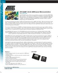
Figure 9 shows an example of how the smart peripherals in the <strong>Infineon</strong><br />
XCM4000 family of products can interface to a quadrature encoder<br />
<strong>with</strong>out the need for a second CPU. The Position Interface peripheral<br />
(POSIF) is set up in Quadrature Decoder mode and conditions the signals<br />
from the encoder.<br />
Figure 9: Connection and configuration of the POSIF and CCU4 for decoding a quadrature encoded rotor position<br />
and speed.<br />
It is also connected via a connection matrix to one of the capture/compare<br />
modules (CCU4). The counter in Slice 0 of the CCU4 is incremented and<br />
decremented automatically (depending on the motor direction) and<br />
contains the motor position. The counter in Slice 1 is incremented each<br />
revolution based on the IDX signal to provide a revolution count. Slices 2<br />
and 3 are both used to capture velocity. Slice 2 measures the number of<br />
encoder edges per given time interval. Slice 3 measures the time between<br />
a fixed number of encoder edges. This allows very fast and very slow<br />
speeds to be accurately measured <strong>with</strong>out the need for the CPU to<br />
reconfigure the peripheral.<br />
Conclusion<br />
<strong>Complex</strong> motor control algorithms require sophisticated mathematics<br />
and hard, real-time performance. The ARM Cortex-M4 CPU operating at<br />
>100 MHz <strong>with</strong> DSP extensions and a hardware floating point unit,<br />
has the CPU bandwidth to perform the high level calculations required<br />
in motor control systems. The CMSIS DSP Library contains many useful<br />
functions such as the Clarke and Park Transforms, and PID controllers<br />
in both fixed and floating point format. This makes the high level<br />
mathematics easier to implement and more portable. With smart<br />
connected peripherals such as those found in the <strong>Infineon</strong> XMC4000<br />
products, complex high-end motor control algorithms can be easily<br />
implemented <strong>with</strong> a single, standard core, reducing development effort<br />
and increasing portability.<br />
END