Photosensitive Materials for Integrated Optic ... - ResearchGate
Photosensitive Materials for Integrated Optic ... - ResearchGate
Photosensitive Materials for Integrated Optic ... - ResearchGate

You also want an ePaper? Increase the reach of your titles
YUMPU automatically turns print PDFs into web optimized ePapers that Google loves.
FIO 24(3-4) #52236<br />
Fiber and <strong>Integrated</strong> <strong>Optic</strong>s, 24:149–169, 2005<br />
Copyright © Taylor & Francis Inc.<br />
ISSN: 0146-8030 print/1096-4681 online<br />
DOI: 10.1080/01468030590922696<br />
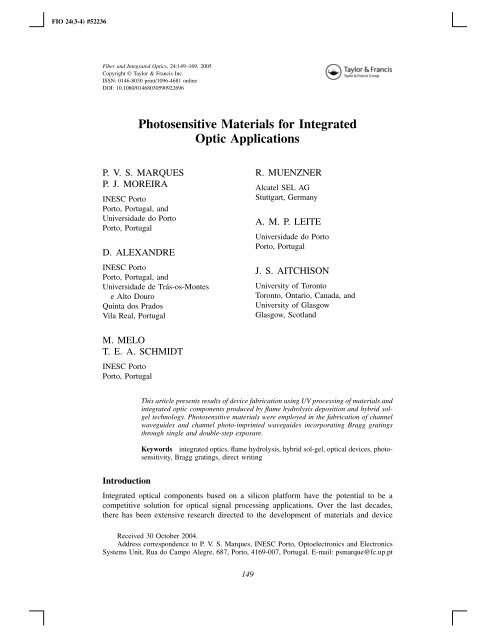
<strong>Photosensitive</strong> <strong>Materials</strong> <strong>for</strong> <strong>Integrated</strong><br />
<strong>Optic</strong> Applications<br />
P. V. S. MARQUES<br />
P. J. MOREIRA<br />
INESC Porto<br />
Porto, Portugal, and<br />
Universidade do Porto<br />
Porto, Portugal<br />
D. ALEXANDRE<br />
INESC Porto<br />
Porto, Portugal, and<br />
Universidade de Trás-os-Montes<br />
e Alto Douro<br />
Quinta dos Prados<br />
Vila Real, Portugal<br />
R. MUENZNER<br />
Alcatel SEL AG<br />
Stuttgart, Germany<br />
A. M. P. LEITE<br />
Universidade do Porto<br />
Porto, Portugal<br />
J. S. AITCHISON<br />
University of Toronto<br />
Toronto, Ontario, Canada, and<br />
University of Glasgow<br />
Glasgow, Scotland<br />
M. MELO<br />
T. E. A. SCHMIDT<br />
INESC Porto<br />
Porto, Portugal<br />
This article presents results of device fabrication using UV processing of materials and<br />
integrated optic components produced by flame hydrolysis deposition and hybrid solgel<br />
technology. <strong>Photosensitive</strong> materials were employed in the fabrication of channel<br />
waveguides and channel photo-imprinted waveguides incorporating Bragg gratings<br />
through single and double-step exposure.<br />
Keywords integrated optics, flame hydrolysis, hybrid sol-gel, optical devices, photosensitivity,<br />
Bragg gratings, direct writing<br />
Introduction<br />
<strong>Integrated</strong> optical components based on a silicon plat<strong>for</strong>m have the potential to be a<br />
competitive solution <strong>for</strong> optical signal processing applications. Over the last decades,<br />
there has been extensive research directed to the development of materials and device<br />
Received 30 October 2004.<br />
Address correspondence to P. V. S. Marques, INESC Porto, Optoelectronics and Electronics<br />
Systems Unit, Rua do Campo Alegre, 687, Porto, 4169-007, Portugal. E-mail: psmarque@fc.up.pt<br />
149
150 P. V. S. Marques et al.<br />
fabrication methods <strong>for</strong> the development of pe<strong>for</strong>mant integrated optic solutions. Among<br />
the technologies exploited, those related to silica-based materials are particularly relevant,<br />
of which flame hydrolysis and hybrid sol-gel techniques deserve particular attention.<br />
The flame hydrolysis deposition technique is a vapor delivery method developed<br />
to synthesize high-purity fine silica particles through a hydrolysis process in a hightemperature<br />
flame, using an oxy-hydrogen torch. Kawachi et al. [1] were the first to<br />
apply flame hydrolysis deposition (FHD) to the realization of planar lightwave circuits<br />
(PLCs) due to its high throughput, excellent doped silica quality, and versatility in terms<br />
of doping species. Since this first work, numerous results have been published confirming<br />
FHD, in conjunction with reactive ion etching (RIE), as a very per<strong>for</strong>mant technique <strong>for</strong><br />
PLC production. In addition, the FHD process has been used to fabricate lanthanidedoped<br />
waveguide lasers and amplifiers in silica [2].<br />
The hybrid sol-gel process is a promising route <strong>for</strong> production of low-cost organic–<br />
inorganic,glass-basedintegratedopticaldevices,asitofferstheadvantageoflow-temperature<br />
fabrication and does not require sophisticated equipment [3]. The presence of the organic<br />
components increases the flexibility of the gel network, preventing its cracking,<br />
permitting low consolidation temperatures, and opening the possibility to combine the<br />
attractive features of organic polymers with those of a silicate network at the molecular<br />
level. Adequate choice of an organic polymeric group allows the definition of microstructures,<br />
such as channel waveguides, using simple, low-cost photopolymerization as<br />
an alternative to the complex dry-etching procedure used with purely inorganic glass [4].<br />
One property that can be an attribute to materials produced via the two synthesis<br />
techniques referred above is photosensitivity, which has been exploited in the fabrication<br />
of fiber and planar devices, an ef<strong>for</strong>t stimulated by the extremely important role of the<br />
resulting devices in optical communication and sensing systems. It should, however, be<br />
emphasized that in the case of inorganic materials the photosensitivity is mainly due to<br />
oxygen defect centers [5], while in hybrid sol-gel materials the refractive index changes<br />
arise from a structural change of the organic component [6].<br />
In the case of purely inorganic materials such as those produced by FHD, the photosensitivity<br />
effect has been used primarily to produce in-core Bragg gratings using the<br />
permanent index change obtained under UV exposure [7, 8]. The same effect can also<br />
be usefully employed in UV trimming of devices [9, 10] and in direct writing of 2-D<br />
components, such as directional couplers [11, 12] and power splitters [12]. Direct writing<br />
is particularly attractive since it avoids recourse to expensive and time-consuming RIE<br />
in defining the waveguide structures. Attention is, there<strong>for</strong>e, beginning to focus on the<br />
use of photosensitivity as a method <strong>for</strong> transferring the waveguide device pattern into the<br />
silica glass.<br />
In the case of the hybrid material synthesized from the precursor methacryloxypropyltrimethoxysilane<br />
(MAPTMS), the organic groups contain unsaturated C=C double bonds,<br />
so they can be photopolymerized by ultraviolet (UV) radiation exposure [6], thus becoming<br />
resistant to organic solvents, whereas the unexposed material can be simply dissolved<br />
away by a suitable organic solvent [13]. The addition of photoinitiators in the<br />
final preparation step of the sol-gel solution, such as Irgacure 184 or 1800 (CIBA) or<br />
hydroxymethylpropiophenone (HMPP), has been employed [14, 15]. There<strong>for</strong>e, the photosensitive<br />
properties of this class of materials allow the fabrication of integrated devices<br />
without recourse to RIE.<br />
In this article, the production of integrated devices employing photosensitivity as<br />
an essential characteristic <strong>for</strong> the device fabrication routine is described. In the case<br />
of materials produced by FHD, the fabrication of Bragg gratings in etched waveguides
<strong>Photosensitive</strong> <strong>Materials</strong> <strong>for</strong> <strong>Integrated</strong> <strong>Optic</strong>s 151<br />
is reported, followed by the explanation of direct writing experiments that allow the<br />
fabrication of devices without reactive ion-etching processes. In the case of hybrid materials,<br />
tridimensional waveguide fabrication through photo-polymerization and dissolution<br />
is described in detail. Simultaneous photo-imprinting of a straight waveguide with a<br />
Bragg grating incorporated in its central section is reported <strong>for</strong> both inorganic and hybrid<br />
materials.<br />
Experiments<br />
The FHD Synthesis Route<br />
The Deposition System. The FHD system assembled at Glasgow University, which was<br />
used to partially produce the samples used on this work [16], incorporates a reagents<br />
cabinet, which consists of a sealed glove box that contains the bubbler bottles with<br />
their respective reagents (SiCl 4 , POCl 3 , and GeCl 4 ), a deposition chamber, and a waste<br />
scrubber. The final glass composition is determined by the carrier gas (N 2 ) flow to each<br />
reagent bottle, which is regulated through high-precision mass flow controllers (MFCs).<br />
Since this method relies on a vapor delivery technique, the reagents are kept at constant<br />
temperature (by silicone oil circulating in a closed circuit in the outer jacket of their<br />
respective reagent Drechels bottles) in order to ensure a good process control. BCl 3 was<br />
already supplied as a gas and there<strong>for</strong>e used a separated delivery line.<br />
The hydrolysis reaction takes place in the closed deposition chamber (at atmospheric<br />
pressure), which houses the circular turntable where the substrates are placed and the<br />
oxy-hydrogen torch. Two computer-controlled stepper motors are assembled underneath<br />
the chamber, one used <strong>for</strong> turntable rotation and the other <strong>for</strong> the linear movement of the<br />
arm that holds the torch. The final thickness of the glass layer deposited is determined<br />
by the combined movements of rotation of the turntable and linear displacement of the<br />
torch above the substrates. A local exhaust is placed above the turntable surface in order<br />
to ensure an efficient removal of corrosive reaction products and unreacted reagents.<br />
Calibration of the FHD system was first conducted using planar waveguides produced<br />
on oxidized silicon wafers. The most important characteristics to be determined<br />
are the thickness and the refractive index of the slab layer versus dopants concentration,<br />
as well as the optimal sintering conditions required to achieve defect-free glass layers.<br />
Several fabrication parameters were investigated, such as reagent flow, flame and turntable<br />
temperature, torch position, and sintering parameters (dwell temperature and time, temperature<br />
ramps, and sintering environment). In all cases the flame was fed with constant<br />
flow rates <strong>for</strong> SiCl 4 (150 cm 3 /min) and BCl 3 (65 cm 3 /min), while the GeCl 4 flow rate<br />
was adjusted in order to control the refractive index difference to the thermal silicon oxide<br />
layer. Flame fueling was ensured by constant flows of O 2 (5 L/min) and H 2 (7 L/min),<br />
as a more efficient incorporation of germanium was found with high-temperature flames,<br />
probably due to better reaction efficiency. The samples were sintered in a tubular furnace<br />
in a helium-rich environment, produced by a constant helium flow of 0.6 L/min. The<br />
sintering temperature was approximately 1325 ◦ C <strong>for</strong> a dwell time of 2.5 h. The samples<br />
were inserted and removed at approximately 850 ◦ C and the ramping rates employed were<br />
15 ◦ C/min. As an example of the characterization of the fabrication procedure, Figure 1<br />
shows the results of the refractive index as a function of the GeCl 4 flow rate, which<br />
are relevant <strong>for</strong> the proper deposition of waveguide core layers. The refractive index of<br />
the planar layer was measured using the m-lines technique. The parameters employed<br />
resulted in a final layer thickness of 1.0 ± 0.1 µm per pass of the torch.
152 P. V. S. Marques et al.<br />
Figure 1. Flame hydrolysis deposition system calibration <strong>for</strong> germano-borosilicate glass. The<br />
SiCl 4 and BCl 3 flow rates were 150 and 65 cm 3 /min, respectively. The oxygen and hydrogen<br />
flow rates were 7 and 5 L/min, respectively.<br />
Photosensitivity Assessment and Device Fabrication<br />
Bragg gratings. Following FHD system calibration, the photosensitive response of<br />
germanium-boron–doped silica layers was assessed as deposited and after photosensitivity<br />
enhancement (either through cold hydrogenation or flame brushing).<br />
The refractive index changes in planar waveguides due to UV exposure were determined<br />
by protecting half of the sample while uni<strong>for</strong>mly exposing the other half. The<br />
changes were determined by comparing the refractive index of both areas, as given<br />
by the prism coupler and m-lines technique. The saturation values <strong>for</strong> index change in<br />
planar waveguides (core thickness of 6 µm and relative refractive index difference of<br />
n<br />
n<br />
= 0.75%) due to UV exposure, using a KrF excimer laser operating at 248 nm, were<br />
5 × 10 −4 <strong>for</strong> as-grown samples and 4 × 10 −3 <strong>for</strong> flame-brushed samples (due to the absence<br />
of a cladding layer, flame brushing employing an oxy-hydrogen torch [17] was used<br />
as the photo-sensitization method, since flame brushing induces permanent hydrogenation<br />
as opposed to “cold” hydrogenation at high pressure, where molecular hydrogen<br />
will rapidly diffuse out). In addition, Bragg gratings were written into standard channel<br />
waveguides defined by reactive ion etching and buried using a cladding layer, with<br />
the refractive index matching that of the thermal silicon dioxide buffer. Gratings were<br />
photo-imprinted using the conventional phase mask approach. The transmission spectrum<br />
evolution due to UV exposure through a 6-mm-long phase mask (period of 1060 nm) in<br />
an etched waveguide with a relative refractive index contrast to the thermal buffer layer<br />
of 0.75% and core dimensions of 6 × 6 µm 2 can be seen in Figure 2. The samples were
<strong>Photosensitive</strong> <strong>Materials</strong> <strong>for</strong> <strong>Integrated</strong> <strong>Optic</strong>s 153<br />
Figure 2. Evolution of the Bragg grating transmission spectrum with UV exposure (200 mJ/cm 2<br />
per pulse at 20 Hz). The narrowest and the broadest spectra were obtained with 4500 and 35,000<br />
pulses, respectively.<br />
hydrogen loaded prior to UV exposure <strong>for</strong> ∼2 weeks in a high-pressure chamber (120<br />
atm, room temperature). Analysis of the evolution of the grating spectral characteristics<br />
shows that the central Bragg wavelength moves toward longer wavelengths as the exposure<br />
proceeds, due to an increase of the average core refractive index. Simultaneously,<br />
there is an increase of the grating bandwidth and side features start to develop as the<br />
exposure progresses toward saturation. There is a characteristic rise in coupling to higherorder<br />
modes that reflects itself on a drop in transmission at wavelengths shorter than the<br />
central Bragg wavelength. The peak that develops at a longer wavelength is attributed to<br />
e-beam writing stitching errors in the phase mask used.<br />
Figure 3 shows the evolution of the maximum grating reflectivity as a function of the<br />
UV exposure; this behavior is characteristic of germanium-doped silica, which exhibits a<br />
positive refractive index change due to exposure. The refractive index change estimated<br />
from the results of Figures 2 and 3 is a rise of at least 3.6 × 10 −3 .<br />
<strong>Integrated</strong> lasers. Intra-core Bragg gratings offer an elegant solution to <strong>for</strong>m the laser<br />
cavity in comparison with dielectric mirrors butt-coupled or directly deposited on the<br />
waveguide ends. The fabrication of a monolithic laser configuration requires a successful<br />
combination of a material capable of UV photo-imprinting of Bragg gratings with a<br />
host with high solubility of lanthanide ions, both properties being closely related to the<br />
core dopants employed. Phosphorous is a suitable co-dopant to achieve high lanthanide<br />
concentration, but adversely reduces the UV absorption bands at the most commonly<br />
employed UV writing wavelengths. Germanium has the opposite characteristics regarding<br />
photosensitivity/solubility. The demonstrated laser configuration is based on a waveguide<br />
core that combines two layers produced by FHD, with the same refractive index but<br />
with different doping characteristics: one exhibits high photosensitivity, while the other
154 P. V. S. Marques et al.<br />
Figure 3. Evolution of peak reflectivity <strong>for</strong> the grating characterized in Figure 2.<br />
has high lanthanide solubility. A schematic representation of the structure fabricated is<br />
represented in Figure 4.<br />
The waveguides were also fabricated by flame hydrolysis deposition and reactive ion<br />
etching. Initially, a 2-µm photosensitive layer was deposited on top of a 15-µm-thick pure<br />
oxide undercladding, obtained by silicon oxidation. This photosensitive layer was doped<br />
with germanium and boron. A second core layer, 4-µm thick, was then deposited and<br />
consolidated. This layer was doped with neodymium and used a phosphorous/aluminumbased<br />
silica host, produced by aerosol doping techniques [18]. The Nd 3+ concentration<br />
is estimated to be ≈0.21 wt% by comparison with measured samples produced under<br />
similar conditions [18]. The core ridges were <strong>for</strong>med by photolithographic processes and<br />
RIE and covered with an overcladding layer with the refractive index matching that of the<br />
thermal oxide buffer. The total core thickness is 6 µm and the relative index difference to<br />
the adjacent layers is 0.75% (the two core layers were index matched). The total sample<br />
length is 5 cm.<br />
Figure 4. Schematic representation of the laser structure.
<strong>Photosensitive</strong> <strong>Materials</strong> <strong>for</strong> <strong>Integrated</strong> <strong>Optic</strong>s 155<br />
The laser cavity was defined by two Bragg gratings, fabricated by UV exposure<br />
to a KrF excimer laser (248 nm) through a fused silica phase mask, as represented in<br />
Figure 4. To enhance the photosensitivity response, the samples were hydrogenated <strong>for</strong><br />
2 weeks at 100 atm (room temperature). The 8-mm-long Bragg gratings were monitored<br />
during the UV exposure using a white light source and an optical spectrum analyzer. Due<br />
to a smaller overlap between the optical mode distribution and the photosensitive layer<br />
in comparison with a uni<strong>for</strong>m Ge-doped core, the gratings reached saturation at around<br />
80% reflectivity and had a bandwidth of about 0.8 nm. The distance between gratings<br />
was 25 mm, corresponding to a free spectral range of about 4.1 GHz (0.015 nm). Since<br />
the active layer was doped with neodymium, the Bragg wavelength was situated near the<br />
peak of the fluorescence band, centered at 1053 nm.<br />
Figure 5 shows the output spectrum recorded with an optical spectrum analyzer <strong>for</strong><br />
a8×6 µm 2 core section waveguide pumped at 802 nm using a Ti:Sapphire laser. The<br />
threshold <strong>for</strong> laser action was 93 mW (estimated coupled pump power, determined by<br />
taking into account non-absorbed pump power, Fresnel, coupling, and scattering losses),<br />
and a slope efficiency of 0.3% was obtained as demonstrated in Figure 6. Since the<br />
gratings are expected to be similar, the total efficiency should be approximately 0.6%. In<br />
Figure 7, the result of a Fabry-Perot scan is represented, demonstrating single longitudinal<br />
mode operation. Monomode operation is thought to be due to the combined effects of<br />
slightly shifted gratings and laser cavity mode spacing.<br />
Channel waveguide writing. The refractive index change usually achievable is sufficient<br />
to attain 2-D confinement, and there<strong>for</strong>e functional devices can be fabricated without<br />
recourse to dry-etching processing stages. In order to evaluate the capability of writing<br />
channel waveguides, the layered planar structure shown in Figure 8 was employed. The<br />
central photosensitive layer, doped with germanium and boron, had a thickness d 1 = 6 µm<br />
Figure 5. Laser output spectrum <strong>for</strong> a pump power of 200 mW (waveguide core section 8×6 µm 2 ).
156 P. V. S. Marques et al.<br />
Figure 6. Laser output power as a function of estimated coupled pump power (waveguide core<br />
section 8 × 6 µm 2 ).<br />
Figure 7. Fabry-Perot scan of the waveguide laser emission, using a free spectral range of 2.1 GHz.<br />
Figure 8. Schematic representation of the cross-section structure of the samples used <strong>for</strong> direct<br />
writing experiments.
<strong>Photosensitive</strong> <strong>Materials</strong> <strong>for</strong> <strong>Integrated</strong> <strong>Optic</strong>s 157<br />
and a relative index difference of 0.9% with respect to the thermal oxide lower cladding.<br />
The phosphorous- and boron-doped cladding thickness was d o = 15 µm thick and its<br />
refractive index matched that of the buffer layer; this cover layer was designed to be<br />
transparent at the writing wavelength, and its thickness was chosen to simultaneously<br />
permit a reasonable hydrogen retention time after removal from the hydrogenation chamber<br />
and avoid serious mask diffraction effects as reported in [7]. The nichrome amplitude<br />
mask was fabricated with standard photolithography and nichrome wet-etching. In another<br />
approach, masks were defined on UV-grade silica plates, which were put in contact<br />
with the sample surface, with the mask facing down. This would in principle reduce<br />
the fabrication time, since a single mask could be used <strong>for</strong> more than one sample, but<br />
the method is more sensitive to mechanical vibrations (which are minimized by pressing<br />
down the mask against the sample with strong clamps specially designed to the effect).<br />
The devices were treated with the same hydrogenation routine as the samples used <strong>for</strong><br />
grating tests. The top view of a set of straight waveguides defined by direct writing is<br />
shown in Figure 9. Diffraction effects are not to be seen, and the waveguide dimensions<br />
clearly reproduce quite well the mask widths.<br />
One negative aspect is that the metallic mask can be damaged by the UV exposure.<br />
The threshold <strong>for</strong> damage was determined to be approximately 300 mJ/cm 2 per pulse at<br />
30 Hz <strong>for</strong> masks on transparent silica plates; in the case of nichrome masks deposited<br />
on the sample surface, the threshold <strong>for</strong> mask damage seemed to be smaller. In the<br />
<strong>for</strong>mer case, UV radiation hits the mask interface in contact with the fused silica, which<br />
is obviously very clean and non-oxidized. In the case of NiCr layers deposited on the<br />
sample surface, the UV light exposes the surface layers that are not so clean (exposed to<br />
the air) and probably oxidized, and this is possibly a cause <strong>for</strong> the lower threshold <strong>for</strong><br />
damage. In Figure 10, the photograph of a sample (top view) with severe NiCr damage<br />
is presented <strong>for</strong> illustration.<br />
One problem associated with direct writing in planar layers that are non-matched in<br />
terms of refractive index values is due to the fact that the optical mode is asymmetric<br />
Figure 9. Top view of a set of directly written straight waveguides with widths ranging from 3 to<br />
18 µm (250 mJ/cm 2 per pulse, 25 Hz, 15 min).
158 P. V. S. Marques et al.<br />
Figure 10. Damage of the mask defined on an 80-nm-thick NiCr layer deposited on the sample<br />
(325 mJ/cm 2 per pulse, 30 Hz, 15 min).<br />
(leading to higher coupling losses) [19] and that <strong>for</strong> strong UV-induced refractive index<br />
changes, the UV written waveguide becomes multimode. These problems can be<br />
overcome by the use of an index-matched layer structure. Figure 11 allows a comparison<br />
of the cross-section of UV-written waveguides in matched and non-matched planar<br />
layer structures, whereas Figure 12 displays the cross-sections of etched and UV-written<br />
waveguides in index-matched structures.<br />
Channel waveguide Bragg gratings. The use of photosensitivity to obtain optical<br />
guidance by refractive index modification, together with a superimposed refractive index<br />
modulation to <strong>for</strong>m a Bragg waveguide grating, was investigated.<br />
Figure 11. Cross section of UV direct written waveguides in (a) non-index–matched structures and<br />
(b) index-matched structures. Parameters are (a) n core = 1.4608, n buffer = 1.4456, n clad = 1.4458,<br />
photosensitive layer thickness = 4.6 µm, clad thickness = 19.9 µm; and (b) n core = 1.4458,<br />
n buffer = 1.4457, n clad = 1.4460, photosensitive layer thickness = 4.2 µm, clad thickness =<br />
15.2 µm (all refractive index values at 1.55 µm).
<strong>Photosensitive</strong> <strong>Materials</strong> <strong>for</strong> <strong>Integrated</strong> <strong>Optic</strong>s 159<br />
Figure 12. Comparison between an etched waveguide and a UV-written waveguide defined in an<br />
index-matched layer structure. The data <strong>for</strong> the UV-written sample (index matched) is the same as<br />
<strong>for</strong> Figure 11.<br />
In a first approach the sample surface was coated with an 80-nm-thick film of<br />
nichrome, and lines with widths ranging from 3 to 10 µm were defined in the nichrome<br />
mask. Exposure proceeded in two steps; in the first, the sample was evenly exposed,<br />
through the mask, to the UV beam, without phase mask (7 minutes, 20 Hz, 200 mJ/cm 2<br />
per pulse), <strong>for</strong> definition of a homogeneous “background” waveguide, and care was taken<br />
in order to ensure that some photosensitivity margin was left. A second exposure step<br />
was then per<strong>for</strong>med through a phase mask aligned with the amplitude mask to define a<br />
Bragg grating in the channel waveguide “pre-defined” in the first exposure (additional<br />
12 minutes exposure, 20 Hz, 200 mJ/cm 2 per pulse). The result is shown in Figure 13,<br />
which corresponds to a ∼80% reflectivity grating in a single-mode waveguide. The central<br />
Bragg wavelength shifted to longer wavelengths in this case, because the effective index<br />
in directly written waveguides was higher than in the etched waveguides referred above.<br />
The short wavelength resonances recorded in this case can also be due to a nonuni<strong>for</strong>m<br />
UV exposure. This situation usually results in a non-constant average refractive index<br />
along the grating length that leads to a symmetrically chirped Bragg grating, causing<br />
Fabry-Perot interference effects to develop in the transmission spectrum.<br />
The exposure time <strong>for</strong> each exposure step was roughly calculated from the growth<br />
dynamics shown in Figure 3, and the objective was to attain a 100% reflectivity grating<br />
after the second exposure. Several factors can be responsible <strong>for</strong> the lower reflectivity<br />
achieved, the most probable being a different growth dynamics from that of Figure 3,<br />
which was obtained <strong>for</strong> samples with different GeO 2 concentration.<br />
The refractive index change was, in this case, extrapolated from the position of the<br />
central Bragg wavelength. Calculations were per<strong>for</strong>med <strong>for</strong> a 6 × 6 µm 2 core with a<br />
refractive index n core + n UV .Forλ B = 1545 nm, the refractive index change was<br />
calculated to be n UV ∼ 6 × 10 −3 (<strong>for</strong> a relative index difference of the photosensitive<br />
layer to the adjacent layers of 0.9%). The insertion loss measured in the same waveguide<br />
was 4.5 dB, using single-mode fibers (mode field diameter of 10.5 µm at1/e). The<br />
calculated coupling loss was approximately 2 dB per end-facet, and thus the estimated<br />
propagation loss was 0.5 dB/cm.<br />
A very positive aspect of simultaneous writing of waveguide plus grating is that<br />
from the central Bragg wavelength (which is directly related to the modal effective index<br />
constant) and from the waveguide dimensions, it is possible to accurately extract the UVinduced<br />
refractive index simply by employing the effective index method. A negative<br />
point in this approach is a more pronounced occurrence of damage in the nichrome mask
160 P. V. S. Marques et al.<br />
Figure 13. Transmission spectrum of a directly written linear waveguide with a Bragg grating<br />
obtained under simultaneous UV exposure.<br />
in zones exposed through the phase mask. The fluence increases at locations of construtive<br />
interference, and hence the threshold, as measured in the free beam, is reduced, but this<br />
fact was not considered in the calculation of the UV fluence level.<br />
The final approach involved the definition of a channel waveguide containing a<br />
Bragg grating by using a combined amplitude and phase mask (Figure 14) and a single<br />
exposure step. In this case the phase mask was covered with a thin metallic layer and the<br />
transparent lines were defined through the phase mask region and aligned perpendicular<br />
to the phase mask grooves. Figure 15 shows the transmission spectrum of a waveguide<br />
containing a Bragg grating in its central part. One negative point of this approach is that<br />
it is difficult to monitor the waveguide/grating growth in real time. A top view of the<br />
waveguides, Figure 16, shows clearly that the waveguide is not so well defined in the<br />
border region of the section containing the Bragg grating. This effect is due to the fact<br />
that there is a narrow end region where only one of the phase mask diffraction orders<br />
exposes the sample. The extent of this region depends on the thickness of the cladding<br />
and on the angle of the ±1 diffraction orders; <strong>for</strong> the phase mask used it is of about 5 µm<br />
large. No problems have been associated with this feature, either in terms of insertion<br />
loss or grating spectral properties.<br />
The Hybrid Sol-Gel Synthesis Route<br />
The production of integrated devices employing the hybrid sol-gel technique involves<br />
the synthesis of core, buffer, and cladding material layers and device pattern definition<br />
through UV exposure, followed by dissolution of non-exposed areas [13].<br />
The ideal sol-gel material <strong>for</strong> the buffer layer should possess the following characteristics:<br />
1) low refractive index; 2) allow crack-free thick film (∼10 µm) deposition in a
<strong>Photosensitive</strong> <strong>Materials</strong> <strong>for</strong> <strong>Integrated</strong> <strong>Optic</strong>s 161<br />
Figure 14. Microphotograph of a combined phase and amplitude mask <strong>for</strong> simultaneous direct<br />
writing of a waveguide containing a Bragg grating.<br />
single step; 3) low optical loss; and 4) low material cost. The solution to achieve crackfree<br />
thick films consists of employing a material with low network connectivity. This can<br />
be accomplished by the choice of a di-functional monomer where the non-hydrolyzable<br />
organic group does not <strong>for</strong>m covalent bonds with the neighbor molecules. Apparently,<br />
the refractive index of the material is associated with the linear chain dimension of<br />
the organic group present in the hybrid material; usually, materials with larger organic<br />
Figure 15. Reflexion spectrum of a Bragg grating in a UV-written waveguide fabricated through<br />
a process of simultaneous writing.
162 P. V. S. Marques et al.<br />
Figure 16. Top view of waveguides exposed to the combined phase and amplitude mask of Figure<br />
14. The arrow indicates the border of the phase mask region.<br />
groups have a higher refractive index. So, the starting option is the choice of the short<br />
methyl group (−CH 3 ) <strong>for</strong> the organic component; corresponding di-functional precursors<br />
are dimethyldimethoxysilane (DMDMOS) or dimethyldiethoxysilane (DMDEOS).<br />
Although DMDMOS is more expensive than DMDEOS, in the experiments per<strong>for</strong>med<br />
it was preferred over DMDEOS as the methoxide groups react faster than the ethoxide<br />
groups in the hydrolysis reaction, and thus the preparation time of the sol is reduced.<br />
DMDMOS was combined with tetramethoxysilane (TMOS) with different molar ratios<br />
TMOS:DMDMOS of x:1, where x = 0.5, 0.7, 0.8, 0.9, 1.0 were experimented. Among<br />
the possible solutions, the TMOS/DMDMOS system with a molar ratio of 0.8:1 presented<br />
the best results concerning homogeneity and surface uni<strong>for</strong>mity of the films. This<br />
composition was thus chosen <strong>for</strong> fabrication of buffer/cladding layers.<br />
Hydrolysis and condensation was per<strong>for</strong>med by mixing acidified water (0.1 M HCl)<br />
and the sols were stirred in a sealed container <strong>for</strong> a few hours until reaching the necessary<br />
viscosity to produce spin-coated thick films (∼10 µm or above). The total water quantity<br />
was calculated attending to the specific combination ratio of the alkoxides employed and<br />
to their respective partial water:alkoxide molar ratios; molar ratios of 2:1 <strong>for</strong> tetraalkoxide<br />
(TMOS), 1.5:1 <strong>for</strong> trialkoxide (MTMOS), and 1:1 <strong>for</strong> dialkoxide (DMDMOS) were<br />
employed.<br />
The buffer/cladding layers were deposited at 800 rpm by spin-coating on sodalime<br />
glass substrates previously cleaned using a standard cleaning sequence. They were
<strong>Photosensitive</strong> <strong>Materials</strong> <strong>for</strong> <strong>Integrated</strong> <strong>Optic</strong>s 163<br />
allowed to dry in a clean room environment <strong>for</strong> a few hours and were subsequently kept<br />
at 85 ◦ C during 12 h.<br />
The waveguide core material was synthesized in a similar way to the one reported<br />
in [13] and [15], based on hydrolysis and polycondensation of MAPTMS, to which<br />
zirconium(IV) propoxide (ZPO) mixed with methacrylic acid (MA) was added in a<br />
suitable molar proportion to attain the desired value of the refractive index. The precursor<br />
MAPTMS, diluted in ethanol, was first pre-hydrolyzed with acidic water (0.01 M<br />
HCl) in a water/MAPTMS molar ratio of 0.75 and stirred <strong>for</strong> 15 min. ZPO stabilized<br />
with MA and diluted with ethanol in molar ratios of 1:1:3, respectively, was stirred <strong>for</strong><br />
1 h and mixed with prehydrolyzed MAPTMS under vigorous stirring. Additional acidified<br />
water was added to the mixture until a water/MAPTMS molar ratio of 1.5 was<br />
achieved. After 30 min, the solution was filtered through a 0.2-µm filter and was ready<br />
<strong>for</strong> spin-coating deposition (using a procedure developed to achieve reproducible film<br />
thickness). Soda-lime glass substrates (refractive index of 1.513 at 632.8 nm) were employed,<br />
which had been previously cleaned through a standard cleaning sequence. The<br />
planar films were prebaked at 100 ◦ C <strong>for</strong> 30 min, to evaporate the residual solvent and<br />
avoid sticking when in contact with the photolithographic mask (lines from 4 µm to<br />
24 µm, step 2 µm, ±0.5 µm). The films were then exposed through the amplitude mask<br />
<strong>for</strong> about 30 s to the UV radiation of a 248-nm pulsed excimer laser; the fluence was<br />
240 mJ/cm 2 and the pulse frequency was 10 Hz. The exposed samples were then soaked<br />
<strong>for</strong> a few minutes in ethanol <strong>for</strong> dissolution and removal of the unexposed material.<br />
After rinsing with pure water and drying, the samples with patterned ridge waveguides<br />
were post-baked at 130 ◦ C <strong>for</strong> 24 h. Finally, careful cleaving of both ends of the samples<br />
achieved the required optical interface quality <strong>for</strong> coupling the channel waveguides to<br />
optical fibers.<br />
The refractive index and thickness of the hybrid glass films were usually evaluated<br />
employing a prism coupler setup, with a 0.6328-µm He-Ne laser. The refractive index of<br />
the hybrid glass material versus ZPO:MAPTMS ratio is shown in Figure 17; the 4:10 ratio<br />
was used in this work. Photoinscription of the channel waveguides by 248 nm irradiation<br />
Figure 17. Refractive index of core planar films as a function of ZPO:MAPTMS percentage<br />
molar ratio.
164 P. V. S. Marques et al.<br />
Figure 18. Microphotograph of the cross-section of buried channel waveguides fabricated on a<br />
silicon substrate.<br />
requires a UV-transparent fused silica mask substrate. It was found that the hybrid material<br />
does not need the addition of any kind of photoinitiator to polymerize when exposed at<br />
this radiation wavelength, contrary to what happens when the exposure is per<strong>for</strong>med<br />
using the 365-nm line of a mercury vapor lamp. The presence of a photoinitiator can<br />
be a drawback because of its potential contribution to the absorption loss of the final<br />
material at 1.55 µm. Good contact between the mask and the pre-baked hybrid film<br />
and optimized exposure parameters resulted in channels with perpendicular sidewalls,<br />
shown in Figure 18. Tolerances of film thickness of ∼ =0.2 µm, ridge waveguide width of<br />
∼=0.5 µm are typical. Surface roughness of planar films is usually below 5 nm; sidewalls<br />
roughness is below 50 nm, shown in Figure 19.<br />
The channel waveguides were characterized in terms of absorption loss (400 to<br />
1800 nm) using wide spectrum light coupled into multimode channel waveguides. The<br />
transmission absorption spectrum was measured with an optical spectrum analyzer and<br />
Figure 19. (a) Electron microscope top view of a device, (b) sidewall detail.
<strong>Photosensitive</strong> <strong>Materials</strong> <strong>for</strong> <strong>Integrated</strong> <strong>Optic</strong>s 165<br />
Figure 20. Relative transmission spectra of highly multimode channel waveguide <strong>for</strong> different UV<br />
post-exposure treatments. Inset shows detail illustrating bleaching of C=C double bonds.<br />
normalized in terms of the white light source spectrum. Figure 20 presents the relative<br />
spectral attenuation of the propagating light in a 2.5-cm-long channel waveguide with<br />
20×6 µm 2 cross section. It is possible to identify an absorption band located at 1190 nm,<br />
which appears whenever the material contains organic components, due to the presence<br />
of C−H bonds.<br />
The influence of the UV exposure dose on the transmission absorption spectrum of<br />
the hybrid material was studied using a double exposure method. In the first step, the UV<br />
dose was the minimum that allowed definition of a ridge waveguide with a good cross<br />
section, which corresponds approximately to 240 mJ/cm 2 at 10 Hz <strong>for</strong> 15 s. The ridge<br />
waveguide was subsequently re-exposed and the transmission spectra were registered,<br />
shown in Figure 20. As expected, the strength of the 1620-nm absorption band decreases<br />
with the exposure dose, indicating that the organic compound still polymerizes through<br />
the consumption of the C=C bonds.<br />
In addition, waveguide and gratings can be produced in a single processing step,<br />
as described <strong>for</strong> the case of planar layers produced by flame hydrolysis deposition.<br />
However, in the case of hybrid sol-gel, the dissolution process leads to a corrugation<br />
grating as displayed in Figure 21. The transmission spectrum corresponding to the grating<br />
of Figure 21 is represented in Figure 22.<br />
Conclusion<br />
The photosensitive response of germanium-boron–doped silica obtained by flame hydrolysis<br />
deposition on oxidized silicon substrates was characterized in this study. The<br />
fabrication of devices using hybrid sol-gel technology using UV-assisted photopolymerization<br />
was described in detail. Additionally, demonstration of Bragg grating fabrication<br />
and direct writing of waveguides with a Bragg grating using the two different material<br />
systems was per<strong>for</strong>med. This was a first step toward a practical method <strong>for</strong> mass<br />
production of elaborate devices avoiding dry-etch processing steps.
166 P. V. S. Marques et al.<br />
Figure 21. Microphotograph of channel waveguides fabricated in hybrid sol-gel after exposure<br />
through a combined mask of Figure 14 and dissolution of non-polymerized areas.<br />
Figure 22. Transmission spectra of waveguide plus grating fabricated in hybrid sol-gel through a<br />
single exposure step.<br />
Acknowledgment<br />
This work was supported partially under project POCTI/ESE/43065/2001 and a Ph.D.<br />
fellowship SFRD/BD/4643/2001 awarded to P. J. Moreira, both with financial support of<br />
FCT–Fundação para a Ciência eaTecnologia. This work was also partially supported by<br />
the European Project PLATON (PLAnar Technology <strong>for</strong> <strong>Optic</strong>al Networks), action line<br />
IST-2002-4.8.3, contract number IST-2001-38168.
<strong>Photosensitive</strong> <strong>Materials</strong> <strong>for</strong> <strong>Integrated</strong> <strong>Optic</strong>s 167<br />
References<br />
1. Kawachi, M., M. Yasu, and T. Edahiro. 1983. Fabrication of SiO 2 –TiO 2 glass planar optical<br />
waveguides by flame hydrolysis deposition. Electron. Lett. 19(15):583.<br />
2. Bonar, J. R., and J. S. Aitchison. 1996. Co-doping effects in rare earth doped planar waveguides.<br />
Proc. IEE—Optoelectronics 143:293.<br />
3. Li, C. Y., J. Chisham, M. Andrews, S. I. Najafi, J. D. Mackenzie, and N. Peyghambarian.<br />
1995. Sol-gel integrated optical coupler by ultraviolet light imprinting. Electron. Lett. 31:271.<br />
4. Holmes, A. S., R. R. A. Syms, L. Ming, and M. Green. 1993. Fabrication of buried channel<br />
waveguides on silicon substrates using spin-on-glass. Appl. Opt. 32:4916.<br />
5. Dong, L., J. L. Archambault, L. Reekie, and D. N. Payne. 1995. Photoinduced absorption<br />
change in germanosilicate per<strong>for</strong>ms: Evidence <strong>for</strong> the colour-center model of photosensitivity.<br />
Appl. Opt. 34:3436.<br />
6. Etienne, P., P. Coudray, Y. Moreau, and J. Porque. 1998. Photocurable sol-gel coatings: Channel<br />
waveguides <strong>for</strong> use at 1.5 µm. J. Sol-Gel Sci. Tech. 13:523.<br />
7. Mizrahi, V., P. J. Lemaire, T. Erdogan, W. A. Reed, and D. J. Digiovanni. 1993. Ultraviolet laser<br />
fabrication of ultrastrong optical fibre gratings and of germania-doped channel waveguides.<br />
Appl. Phys. Lett. 63(13):1727.<br />
8. Maxwell, G. D., R. Kashyap, B. J. Ainslie, D. L. Williams, and J. R. Armitage. 1992. UV<br />
written 1.5 µm reflection filters in single mode planar silica guides. Electron. Lett. 28(22):2106.<br />
9. Jarvis, R. A., J. D. Love, and F. Ladouceur. 1997. Bend-radius reduction in planar waveguides<br />
using UV post-tuning. Electron. Lett. 33(10):892.<br />
10. Kashyap, R., G. D. Maxwell, and B. J. Ainslie. 1993. Laser-trimmed four-port bandpass filter<br />
fabricated in single-mode photosensitive Ge-doped planar waveguide, IEEE Photon. Technol.<br />
Lett. 5(2):191.<br />
11. Maxwell, G. D., and B. J. Ainslie. 1995. Demonstration of directly written directional coupler<br />
using UV induced photosensitivity in a planar silica waveguide. Electron. Lett. 31(2):95.<br />
12. Svalgaard, M. 1997. Direct writing of planar waveguide power splitters and directional couplers<br />
using a focused ultraviolet laser beam. Electron. Lett. 33(20):1694.<br />
13. Najafi, S. I., T. Touam, R. Sara, M. P. Andrews, and M. A. Fardad. 1998. Sol-gel glass<br />
waveguide and grating on silicon. IEEE J. Lightwave Technol. 16:1640.<br />
14. Coudray, P., P. Etienne, Y. Moreau, J. Porque, and S. I. Najafi. 1997. Sol-gel channel waveguide<br />
on silicon: Fast direct imprinting and low cost fabrication. Opt. Commun. 143:199.<br />
15. Fardad, M. A., and M. Fallahi. 1998. Organic-inorganic materials <strong>for</strong> integrated optoelectronics.<br />
Electron. Lett. 34:1940.<br />
16. Marques, P. V. S. 2000. Silica-on-silicon integrated optics by flame hydrolysis deposition.<br />
Ph.D. Thesis, University of Porto, Portugal.<br />
17. Bilodeau, F., B. Malo, J. Albert, D. C. Johnson, K. O. Hill, Y. Hibino, M. Abe, and M. Kawachi.<br />
1993. Photosensitization in optical fiber and silica on silicon/silica waveguides. Opt. Lett.<br />
18(12):953.<br />
18. Bonar, J., J. A. Bebbington, J. S. Aitchison, G. D. Maxwell, and B. J. Ainslie. 1995. Aerosol<br />
doped Nd planar waveguide laser. Electron. Lett. 31:99.<br />
19. Zauner, D., K. Kulstad, J. Rathje, and M. Svalgaard. 1998. Directly UV-written silica-on-silicon<br />
planar waveguides with low insertion loss. Electron. Lett. 34(16):1582.<br />
Biographies<br />
Paulo V. S. Marques received a degree in physics (1991), an M.Sc in optoelectronics<br />
and lasers (1995), and a Ph.D. in physics (silica-on-silicon integrated optics by<br />
flame hydrolysis deposition, 2000), all from the University of Porto, Portugal. He is an<br />
assistant professor at the Faculty of Science, Porto University, and since July 2000 he<br />
has been developing research activity in the Optoelectronics and Electronics Systems
168 P. V. S. Marques et al.<br />
Unit of INESC PORTO, being responsible <strong>for</strong> several national and European research<br />
contracts. His current research interests include hybrid sol-gel–based waveguides, optical<br />
photosensitivity, Bragg gratings, electric-field poling, optical switching, and integrated<br />
optical sensors.<br />
António A. M. P. Leite graduated in electrical engineering from the University<br />
of Porto, Portugal, in 1973. In 1979 he was awarded a Ph.D. from University College<br />
London, Department of Electronic and Electric Engineering, <strong>for</strong> research in holographic<br />
optical elements. Appointed associate professor at the Department of Physics, University<br />
of Porto, in 1979, he has been involved since then in projects on optical communication,<br />
fiber sensors, and integrated optic devices in lithium niobate, III-V semiconductors,<br />
polymers, and glass. His current interests are in the field of integrated optics (glass and<br />
polymer devices, electro-optic and rare-earth doped devices), fiber sensors, and sensor<br />
networks.<br />
Paulo J. Moreira graduated in physics and applied mathematics and then concluded<br />
a Masters course in optoelectronics and lasers in the Physics Department of the University<br />
of Porto. He is currently a Ph.D. student working in the field of hybrid sol-gel <strong>for</strong> the<br />
development of integrated optic applications. His interests include microfabrication and<br />
nanotechnologies.<br />
Miguel Melo was born in Porto, Portugal, in 1976. He graduated in optoelectronics<br />
and lasers from the University of Porto in 2001. He is now working as a researcher in the<br />
Optoelectronics and Electronic Systems Unit of INESC Porto. He is currently an M.Sc<br />
student in the Faculty of Engineering of the University of Porto.<br />
Thomas E. A. Schmidt was born on December 11, 1975, in Wolfach, Germany. In<br />
2002 he received his B.Sc. degree in Microsystems Technology from the University of<br />
Applied Sciences in Zweibruecken, Germany. Thereafter, he worked on position determination<br />
using miniaturized ultrasonic transducers at the University of Applied Sciences in<br />
Zweibruecken. In 2003 he joined the optoelectronics group at INESC Porto, where he is<br />
currently involved in developing thermo-optical switches using hybrid sol-gel technology.<br />
His research interests include microfabrication processes and MEMS.<br />
Daniel Alexandre received a degree in electrical engineering (1999) from the University<br />
of Trás-os-Montes e Alto Douro and an M.Sc in optoelectronics and lasers (2003)<br />
from the University of Porto, Portugal. He is a teaching assistant at the University of<br />
Trás-os-Montes e Alto Douro and since 2002 he has been developing research in the Optoelectronics<br />
and Electronics Systems Unit of INESC PORTO. He is currently a Ph.D.<br />
student working in the field of laser direct writing <strong>for</strong> the development of integrated optic<br />
applications. His interests include microfabrication, laser direct writing, and integrated<br />
optical devices.<br />
Roland Muenzner graduated in physics from the University of Tuebingen, Germany,<br />
in 1996, where he also obtained his doctorate in physics in 2001. Since the beginning of<br />
2001 he has worked <strong>for</strong> Alcatel Research & Innovation at Stuttgart, Germany. There the<br />
focus of his research activities from 2001 to 2003 has been on passive integrated optical<br />
components, which has since switched to broadband wireless access systems.<br />
J. Stewart Aitchison received a B.Sc. (with first class honors) and a Ph.D. from the<br />
Physics Department, Heriot-Watt University, Edinburgh, U.K., in 1984 and 1987 respectively.<br />
His dissertation research was on optical bistability in semiconductor waveguides.<br />
From 1988 to 1990 he was a Postdoctoral Member of Technical Staff at Bellcore, Red<br />
Bank, New Jersey. His research interests were in high nonlinearity glasses and spatial<br />
optical solitons. He then joined the Department of Electronics and Electrical Engineering,<br />
University of Glasgow, in 1990, and was promoted to a personal chair as professor of
<strong>Photosensitive</strong> <strong>Materials</strong> <strong>for</strong> <strong>Integrated</strong> <strong>Optic</strong>s 169<br />
photonics in 1999. His research was focused on the use of the half-band-gap nonlinearity<br />
of III-V semiconductors <strong>for</strong> the realization of all-optical switching devices and the study<br />
of spatial soliton effects. He also worked on the development of quasi-phase-matching<br />
techniques in III-V semiconductors, monolithic integration, optical rectification, and planar<br />
silica technology. His research group developed novel optical biosensors, waveguide<br />
lasers, and photosensitive direct writing processes based around the use of flame hydrolysis<br />
deposited (FHD) silica. In 1996 he was the holder of a Royal Society of Edinburgh<br />
Personal Fellowship and carried out research on spatial solitons as a visiting researcher<br />
at CREOL, University of Central Florida. He currently holds the Nortel Institute chair<br />
in Emerging Technology at the University of Toronto, Ontario, Canada. His research interests<br />
cover all-optical switching and signal processing, optoelectronic integration, and<br />
optical bio-sensors. His research has resulted in 7 patents, approximately 130 journal<br />
publications, and 200 conference publications. Dr. Aitchison is a member of the <strong>Optic</strong>al<br />
Society of America, a senior member of the IEEE, and a Fellow of the Institute of<br />
Physics, London.