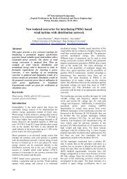
Permanent magnet axial-flux generator with toroidal winding
Permanent magnet axial-flux generator with toroidal winding
Permanent magnet axial-flux generator with toroidal winding

You also want an ePaper? Increase the reach of your titles
YUMPU automatically turns print PDFs into web optimized ePapers that Google loves.
Doctoral school of energy- and geo-technology<br />
January 15–20, 2007. Kuressaare, Estonia<br />
<strong>Permanent</strong> <strong>magnet</strong> <strong>axial</strong>-<strong>flux</strong> <strong>generator</strong> <strong>with</strong> <strong>toroidal</strong> <strong>winding</strong><br />
Ants Kallaste, Aleksander Kilk<br />
Tallinn University of Technology<br />
Ants.Kallaste@ttu.ee, Kilk@cc.ttu.ee<br />
Abstract<br />
This paper analyzes of <strong>toroidal</strong> <strong>winding</strong> permanent<br />
<strong>magnet</strong> <strong>axial</strong>-<strong>flux</strong> wind <strong>generator</strong>. Special<br />
attention is paid on peculiarities and output<br />
characteristics. The experimental <strong>generator</strong> has<br />
been designed and constructed on the base of this<br />
construction approach. Testing experimental<br />
<strong>generator</strong> allows to compare test result <strong>with</strong><br />
simplified calculation method and is also possible<br />
to optimize the permanent <strong>magnet</strong> <strong>generator</strong><br />
construction<br />
Keywords<br />
Generator, permanent <strong>magnet</strong>, <strong>axial</strong>-<strong>flux</strong>, <strong>toroidal</strong><br />
<strong>winding</strong>, calculation method<br />
Introduction<br />
<strong>Permanent</strong> <strong>magnet</strong> (PM) machines have been<br />
replacing other types of electrical machines in many<br />
places. Higher reliability of PM materials, their<br />
higher energy density, their greater corrosion<br />
resistance and the de<strong>magnet</strong>izing influence are the<br />
main causes of developing PM <strong>generator</strong>s. New PM<br />
materials are also less sensitive to temperature<br />
changes. In recent years contemporary power<br />
electronics of high efficiency, high reliability and<br />
decreasing cost offers the possibility to change the<br />
output voltage and frequency of the <strong>generator</strong> to<br />
match the system needs.<br />
The main requirements for wind-<strong>generator</strong>s<br />
designing are as follows:<br />
• Simple construction<br />
• Light weight<br />
• Low speed<br />
• High output power<br />
• Variable-speed generation<br />
• Low cost.<br />
For changing wind energy to electrical energy,<br />
different PM <strong>generator</strong> construction solutions are<br />
analyzed. In addition to some construction solutions<br />
similar to classical hydro- and turbo-<strong>generator</strong>s,<br />
which are working on radial fields in air-gap, also<br />
<strong>axial</strong> <strong>flux</strong> machines are used [1]. Generator<br />
constructions may also differ in <strong>winding</strong> and <strong>magnet</strong><br />
arrangement.<br />
The construction idea of the PM <strong>generator</strong> in this<br />
paper bases on the <strong>axial</strong> <strong>flux</strong> machine analysis [2].<br />
As the construction of the machine seemed to be<br />
very complicated and difficult to produce, a different<br />
solution <strong>with</strong> <strong>toroidal</strong> <strong>winding</strong> was researched. The<br />
main requirements for the new solution were: simple<br />
construction and ability to function as a directly<br />
driven wind-<strong>generator</strong>. It was also important to get<br />
sinusoidal voltage and current waveforms. To meet<br />
these requirements, the <strong>flux</strong> density surrounding the<br />
active parts of <strong>winding</strong> must change according to<br />
cosine dependency. Based on these principals and<br />
ideas the authors designed in 2003 a new <strong>generator</strong>,<br />
where 2 stators and 1 rotor are used in every phase.<br />
According to a patent research, carried out by<br />
authors in 2005, the <strong>generator</strong> construction was not<br />
actually a new solution, because a similar idea was<br />
described before [3].<br />
1 Machine overview<br />
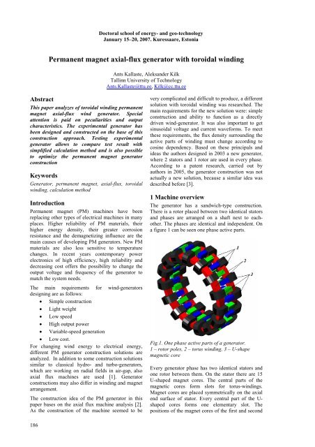
The <strong>generator</strong> has a sandwich-type construction.<br />
There is a rotor placed between two identical stators<br />
and phases are arranged on a shaft next to eachother.<br />
The phases are identical and independent. On<br />
a figure 1 can be seen one phase active parts.<br />
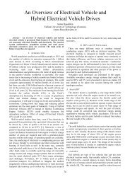
Fig.1. One phase active parts of a <strong>generator</strong>.<br />
1 – rotor poles, 2 – torus <strong>winding</strong>, 3 – U-shape<br />
<strong>magnet</strong>ic core<br />
Every <strong>generator</strong> phase has two identical stators and<br />
one rotor between them. On the stator there are 15<br />
U-shaped <strong>magnet</strong> cores. The central parts of the<br />
<strong>magnet</strong>ic cores form slots for torus-<strong>winding</strong>s.<br />
Magnet cores are placed symmetrically on the <strong>axial</strong><br />
end surface of stator. Every central part of the U-<br />
shaped cores forms one elementary slot. The<br />
positions of the <strong>magnet</strong> cores of the first and second<br />
186
N<br />
S<br />
N<br />
S<br />
N<br />
N<br />
N<br />
S<br />
S<br />
stator are not identical – the <strong>magnet</strong> cores of the first<br />
stator are shifted by one core-width step compared<br />
to the cores of the second stator. Every stator has<br />
one or more torus-<strong>winding</strong>(s) in its slots.<br />
Active part of a rotor consists of permanent <strong>magnet</strong>s<br />
and rotor poles. NdFeB permanent <strong>magnet</strong>s are<br />
placed between rotor poles. Rotor poles direct<br />
<strong>magnet</strong> fields through the air-gap from rotor to<br />
stator. There are 30 rotor poles symmetrically fixed<br />
to the rotor disc, and for every stator slot there is one<br />
pair of poles. Rotor disc has to be made of<br />
dia<strong>magnet</strong>ic and preferably non-conductive material.<br />
Around the perimeter of the rotor the direction of<br />
<strong>magnet</strong>ic <strong>flux</strong> in the one rotor pole is opposite of the<br />
<strong>flux</strong> direction in the next rotor pole. For example:<br />
NS, then SN, and then NS etc (Fig. 3). This type of<br />
construction enables <strong>magnet</strong>ic <strong>flux</strong> around the<br />
elementary slots change according to cosine<br />
function.<br />
2<br />
5<br />
4<br />
6<br />
3<br />
1<br />
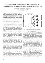
Fig.2. Active part of a stator consisting of<br />
15 elementary stator zones, 1 – U-shaped <strong>magnet</strong>ic<br />
core, 2 – stator slot, 3 – torus-<strong>winding</strong>, 4 – active<br />
part of a <strong>winding</strong>, 5 – passive part of a <strong>winding</strong>,<br />
6 – elementary stator zone<br />
S<br />
N<br />
S<br />
N<br />
S<br />
N<br />
N<br />
S<br />
S<br />
N<br />
S<br />
S<br />
N<br />
1<br />
S<br />
S<br />
2<br />
3<br />
S<br />
N<br />
S<br />
S<br />
S<br />
N<br />
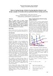
permanent <strong>magnet</strong> (Figure 4) goes through a closed<br />
contour, what is formed by:<br />
• 2 pairs of rotor poles,<br />
• The permanent <strong>magnet</strong> of the rotor,<br />
• 2 air gaps,<br />
• A <strong>magnet</strong>ic core of the stator<br />
The active part of the stator is formed by a U-shaped<br />
<strong>magnet</strong>ic core and a torous <strong>winding</strong>, what is placed<br />
in a slot.<br />
3<br />
1<br />
N<br />
4<br />
2<br />
S<br />
N<br />
S<br />
5<br />
Fig. 4. Fragment of the active part of the <strong>generator</strong>.<br />
1 – PM, 2 – rotor poles, 3 – stator core,<br />
4 – <strong>magnet</strong>ic <strong>flux</strong>, 5 – air gap<br />
N<br />
N<br />
S<br />
S<br />
N<br />
S<br />
N<br />
S<br />
4<br />
N<br />
N<br />
N<br />
Figure 5 explains the operating principles of the<br />
<strong>generator</strong>. If the rotor is rotating to the direction<br />
indicated in Fig. 5 <strong>with</strong> speed ω, then the <strong>flux</strong><br />
density value in the closed <strong>magnet</strong>ic circuit will<br />
change. When the active parts of the rotor and the<br />
stator are in parallel positions, then the <strong>magnet</strong>ic<br />
<strong>flux</strong> value is in its peak level. The <strong>magnet</strong>ic <strong>flux</strong><br />
value decreases to zero, when the pairs of rotor poles<br />
move forward by a half the width of an active part of<br />
the stator. If the pairs of rotor poles move further<br />
from this location, the <strong>magnet</strong>ic <strong>flux</strong> will change its<br />
direction. The <strong>magnet</strong>ic <strong>flux</strong> will be maximized<br />
again, when the active parts will reach new parallel<br />
positions, and all the process will be repeated. The<br />
faster the rotor rotates, the faster the <strong>magnet</strong>ic <strong>flux</strong><br />
changes and the higher will be the value of induced<br />
electromotive force (EMF) amplitude.<br />
N<br />
a) b)<br />
N<br />
N<br />
S<br />
S<br />
S<br />
S<br />
N<br />
N<br />
S<br />
N<br />
S<br />
N<br />
N<br />
S<br />
N<br />
S<br />
N<br />
S<br />
Figure 3. Rotor: 1 – rotor disc, 2 – permanent<br />
<strong>magnet</strong>s, 3 – rotor poles, 4 – elementary rotor<br />
2 Operating principles<br />
The permanent <strong>magnet</strong>s on the rotor are used to<br />
create an activating field for changing mechanical<br />
energy to electrical energy. The <strong>magnet</strong>ic <strong>flux</strong> of the<br />
Fig. 5. Fragments of active <strong>generator</strong> parts<br />
describing the direction change of the rotor<br />
<strong>magnet</strong>ic <strong>flux</strong>: a – direction of <strong>magnet</strong>ic <strong>flux</strong> on first<br />
and second elementary <strong>generator</strong> at starting<br />
position; b) direction of <strong>magnet</strong>ic <strong>flux</strong> after rotor<br />
has turned by one pole step (3 – active <strong>winding</strong>,<br />
2 – end <strong>winding</strong>.<br />
187
3 Generator analysis<br />
The analysis of the <strong>generator</strong> was performed to find<br />
the best calculation method. The steady-state<br />
analysis was performed as first step to get the first<br />
cut of design criteria. Magnetic equivalent circuit<br />
was first used for <strong>magnet</strong>ic analyses. The finiteelement<br />
analysis was performed to refine the<br />
<strong>magnet</strong>ic analysis. Finally, a dynamic analysis was<br />
performed in the laboratory to validate <strong>generator</strong><br />
performance under dynamic condition.<br />
A three-phase PM <strong>generator</strong> consists of three<br />
identical single-phase <strong>generator</strong>s. Every single-phase<br />
<strong>generator</strong> consists of one rotor and two identical<br />
stators. Each stator consists of z elementary stator<br />
and each rotor of 2z elementary rotor zones. For<br />
example: if one stator of a three-phase <strong>generator</strong><br />
equals z = 15 elementary stators and one rotor equals<br />
2z = 30 elementary rotors, then a single-phase<br />
<strong>generator</strong> consists of 30 <strong>generator</strong> sections (let’s<br />
name them elementary <strong>generator</strong>s), and a threephase<br />
<strong>generator</strong> consists of 3 × 2z = 6z identical<br />
elementary <strong>generator</strong>s. In our example it means, that<br />
the <strong>generator</strong> consists of 6z = 6 × 15 = 90 elementary<br />
<strong>generator</strong>s.<br />
The explanation of the nominal characteristics of the<br />
elementary <strong>generator</strong> is as follows. Let the nominal<br />
power of a three-phase <strong>generator</strong> be 9 kW. Then the<br />
calculation of the <strong>generator</strong> will be identical to a<br />
calculation of a 9000 W : 90 = 100 W elementary<br />
<strong>generator</strong>. According to that, in case the power<br />
equals to 100 W, nominal current I n = 10 A and there<br />
are N = 10 elementary wires, the nominal voltage of<br />
an elementary wire is U ne = 1 V. Nominal voltage of<br />
a stator <strong>winding</strong> of the described <strong>generator</strong> equals:<br />
U<br />
= z ⋅U<br />
⋅ N = 15 ⋅1⋅10<br />
= 150<br />
V<br />
n ne<br />
To find out the induced EMF into <strong>winding</strong>s, we have<br />
to calculate the maximum <strong>flux</strong> density in the air-gap.<br />
The maximum <strong>flux</strong> density depends on the<br />
de<strong>magnet</strong>ization characteristic of the permanent<br />
<strong>magnet</strong> (given by the remanence <strong>flux</strong> density B r and<br />
the coercive force H c , and by the geometry of the<br />
air-gap). The quality of the permanent <strong>magnet</strong> can<br />
be estimated by the value of B r multiplied by H c .<br />
The higher the B r × H c value is the higher is the<br />
energy product of the permanent <strong>magnet</strong>. The airgap<br />
between the <strong>magnet</strong> poles decreases the <strong>flux</strong><br />
density compared to the remanence <strong>flux</strong> density in a<br />
closed <strong>magnet</strong>ic circuit<br />
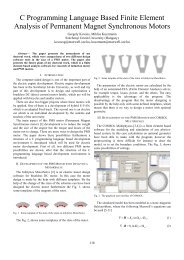
To analyze the <strong>magnet</strong>ic circuit, the finite-element<br />
method was used to compute the <strong>flux</strong> density in the<br />
<strong>generator</strong> components. The main purpose is to get<br />
the overall picture of the leakage <strong>flux</strong> and saturation<br />
level in different parts of the <strong>generator</strong>, the iron<br />
losses in the components of the <strong>generator</strong>, and the<br />
worst case of de<strong>magnet</strong>ization on the permanent<br />
<strong>magnet</strong>.<br />
From <strong>generator</strong> <strong>magnet</strong>ic field analyses was found<br />
that it is not enough to study only two dimensional<br />
<strong>magnet</strong>ic fields because of leakage <strong>flux</strong> in third<br />
dimension. Three dimensional analyse result can be<br />
seen on figure 7. The figure 7 is for <strong>generator</strong> <strong>with</strong> 1<br />
mm air gap.<br />
The distribution of <strong>magnet</strong>ic <strong>flux</strong> density in air gap<br />
(1 mm) between rotor and stator pole is represented<br />
in the Figure 8<br />
Fig.7. Flux density on the surface of elementary<br />
<strong>generator</strong><br />
Fig.8. Distribution of <strong>magnet</strong>ic <strong>flux</strong> density in<br />
air-gap of <strong>generator</strong><br />
From <strong>magnet</strong>ic analyse was found that the leakage<br />
<strong>flux</strong> forms quite a considerable part of the <strong>flux</strong> and it<br />
depends on the air gap. Dependence is presented on<br />
the figure 9.<br />
Fig.9. Air gap <strong>flux</strong> density dependence on air gap<br />
<strong>with</strong> 1– <strong>flux</strong> density <strong>with</strong>out leakage, 2– <strong>flux</strong> density<br />
<strong>with</strong> leakage, 3 – leakage <strong>flux</strong><br />
The simplified equivalent circuit of the <strong>winding</strong> is<br />
described in Fig. 8. The equivalent circuit of the<br />
<strong>generator</strong> consists of:<br />
E<br />
r<br />
x σ<br />
x s<br />
– the induced EMF,<br />
– the resistance,<br />
– the leakage reactance,<br />
– equivalent reactance.<br />
Load consists of impedance Z t and seriescompensating<br />
capacitor x c . The vector diagram of<br />
the equivalent circuit is on the Fig. 10. The active<br />
and reactive resistances of armature reaction are not<br />
described on the equivalent circuit.<br />
188
Fig.10. Simplified equivalent circuit of the <strong>generator</strong><br />
<strong>with</strong> series-compensating capacitor (a) and vector<br />
diagram (b)<br />
4 Experimental study of <strong>generator</strong><br />
The experimental model of a PM <strong>generator</strong> <strong>with</strong><br />
torus-<strong>winding</strong>s was built and tested (figure 11). The<br />
purpose of the experiment was to study and analyze<br />
both the electro<strong>magnet</strong>ic processes as well as the<br />
main operating characteristics of the PM <strong>generator</strong>.<br />
As an aim of experimental study it was to compare<br />
the experimental data <strong>with</strong> the results of design and<br />
calculation. It was not our intention to optimize<br />
construction of the PM <strong>generator</strong>.<br />
Fig.11. Picture of experimental model <strong>generator</strong><br />
We tested the <strong>generator</strong> in some different load<br />
conditions to analyze the influence of load character<br />
to the load characteristics of the PM <strong>generator</strong>. The<br />
<strong>generator</strong> was driven by asynchronous machine,<br />
what was fed via a frequency converter.<br />
The open circuit voltage waveform was captured<br />
<strong>with</strong> the scope (Fig. 12). We can see on the Fig. 12<br />
that the waveform is quite similar to the sine wave<br />
and the total harmonic distortion THD is relatively<br />
low.<br />
U (V)<br />
t (ms)<br />
The load characteristic of the voltage-current of the<br />
<strong>generator</strong> is quite soft. End-<strong>winding</strong>s of the<br />
<strong>generator</strong> are relatively long, making the inductance<br />
of the torus-<strong>winding</strong>s relatively high. To compensate<br />
the inductance of the <strong>generator</strong> <strong>winding</strong>, when it was<br />
loaded, we added a capacitor to the resistive load.<br />
The capacitor gave us much better external<br />
characteristic. Voltage-current characteristic <strong>with</strong> the<br />
inductance of the <strong>generator</strong> compensated by the<br />
capacitor is presented on Fig. 13.<br />
Fig.13. The voltage-current load characteristic <strong>with</strong><br />
the inductance of the <strong>generator</strong> compensated by the<br />
capacitor<br />
5 Conclusion<br />
On the basis of the experiment the constructional<br />
solution of the <strong>axial</strong> <strong>flux</strong> PM wind <strong>generator</strong> <strong>with</strong><br />
U-shaped <strong>magnet</strong>ic cores and torus-<strong>winding</strong>s was<br />
tested and analyzed. A mathematical methods of the<br />
PM <strong>generator</strong> analyzes were studied and the results<br />
were compared <strong>with</strong> experimental data. Different<br />
between mathematical method and experimental<br />
result was small. Also this type of <strong>generator</strong> has<br />
relatively high <strong>flux</strong> leakage it has very simple<br />
construction.<br />
References<br />
1. PEETERS, E., VAN TICHELEN, P.<br />
Design Considerations of an Axial Flux<br />
<strong>Permanent</strong> Magnet Machine <strong>with</strong> U-Shaped<br />
Stator, EPE-PEMC 2002,<br />
Cavtat&Dubrovnik, Croatia, CD, 2002.<br />
2. WEH, H., MAY, H. Achievable Force<br />
Densities for <strong>Permanent</strong> Magnet Exited<br />
Machines in New Configurations, Proc. of<br />
ICEM, 1986.<br />
3. MULJADI, E., BUTTERFIELD, C. P.,<br />
WAN, Y. Axial-Flux modular <strong>Permanent</strong>-<br />
Magnet Generator <strong>with</strong> a Toroidal Winding<br />
for Wind-Turbine Applications. IEEE<br />
Transactions on Industry Applications, Vol.<br />
35, No 4, July/August 1999.<br />
Fig.12. The open circuit voltage waveform, if the<br />
air-gap is 2 mm and the frequency 50 Hz<br />
189