
Create successful ePaper yourself
Turn your PDF publications into a flip-book with our unique Google optimized e-Paper software.
<strong>Cogging</strong> <strong>Torque</strong> <strong>Reduction</strong> <strong>Methods</strong><br />
Oleg Kudrjavtsev, Aleksander Kilk<br />
Tallinn University of Technology (Estonia)<br />
Kudrjavtsev.ol@gmail.com, Aleksander.kilk@ttu.ee<br />
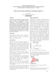
Abstract— This paper considers the study of methods for<br />
reduction of the cogging torque in permanent magnet machines.<br />
<strong>Cogging</strong> torque has been analyzed to be reduced by slot skewing,<br />
width of slot opening, magnet pole radius and also by mounting<br />
of the magnets. Electromagnetic simulations of the PM<br />
generator were performed by using finite element analysis.<br />
Virtual torque method has been used for calculation of the<br />
cogging torque.<br />
I. INTRODUCTION<br />
Use of permanent magnet machines is growing. This kind<br />
of machine has very good efficiency, reliability, small weight<br />
and no need in servicing.<br />
Permanent magnet motors and generators have one<br />
common problem in operation – it is cogging torque.<br />
<strong>Cogging</strong> torque is an internal PM generator feature that<br />
depends on generator’s geometry. <strong>Cogging</strong> torque has influence<br />
on the starting torque, it creates noise and vibration.<br />
<strong>Cogging</strong> torque is affected by a lot of factors as form of the<br />
magnetic field, number of slots per pole and phase, slot<br />
opening and filling factor, pole pitch, distribution of magnetic<br />
flux density. In this study the influence of slot opening, slot<br />
skewing, mounting position of the magnet and magnet pole<br />
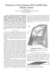
angle have been analyzed. As the main object of this study a 5<br />
kVA PM generator with outer rotor has been analyzed.<br />
study the Virtual torque method has been used for<br />
the calculations.<br />
A. Virtual <strong>Torque</strong> Method<br />
In finite element analysis we must rotate the rotor by small<br />
steps and at each position has to be calculated the change in<br />
the total stored magnetic field energy. The torque that has<br />
been developed in the machine can be written as the partial<br />
change in magnetic field energy with respect to the virtual<br />
displacement of the rotor [2]:<br />
∂WC<br />
T = , (1)<br />
∂θ<br />
where θ is the rotor angular displacement and W c is the<br />
stored energy of magnetic field.<br />
A. Slot Opening<br />
III. COGGING TORQUE REDUCTION METHODS<br />
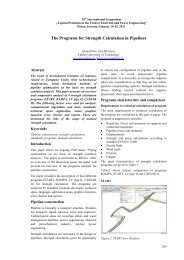
Slot opening has a greate influence on the cogging torque.<br />
Three different slot openings 2, 4, 6 mm have been<br />
investigated and compared to show the difference in change<br />
of cogging torque.<br />
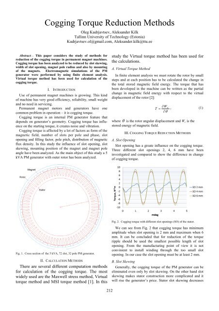
Fig. 2. <strong>Cogging</strong> torque with different slot openings (SO) of the stator.<br />
Fig. 1. Cross section of the 5 kVA, 72 slot, 32 pole PM generator.<br />
II. CALCULATION METHODS<br />
There are several different computation methods<br />
for calculation of the cogging torque. The most<br />
widely used are the Maxwell stress method, Virtual<br />
torque method and MSI torque method [1]. In this<br />
We can see from Fig. 2 that cogging torque has minimum<br />
amplitude when slot opening is 2 mm and maximum when 6<br />
mm. It can be concluded that for reduction of the torque<br />
ripple should be used the smallest possible length of slot<br />
opening. From the manufacturing point of view it is not<br />
convinient to install winding through the too small slot<br />
opening. In our case the slot opening must be at least 2 mm.<br />
B. Slot Skewing<br />
Generally, the cogging torque of the PM generator can be<br />
eliminated even only by slot skewing. On the other hand slot<br />
skewing makes stator construction more complicated and it<br />
will rise the generator’s price. Stator slot skewing decreases<br />
212
the effective cross section of a slot, increases the length of<br />
conductors and decreases the electro motive force of the<br />
machine [3]. The influence of different rate of slot skewing to<br />
the level of cogging torque of PM generator has been<br />
compared in Fig 3.<br />
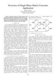
Fig. 5. <strong>Cogging</strong> torque as a function of the rotor magnet mounting method.<br />
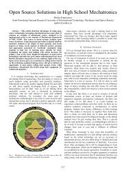
Fig. 3. <strong>Cogging</strong> torque as a function of different stator slot skews.<br />
Fig. 3 shows the cogging torque obtained for some<br />
different slot skews. In our case the cogging torque can be<br />
totally eliminated when slot skew is 0,23 slot pitches. It can<br />
be seen from the graph that 0,03 slot pitches skew can<br />
influence in reduction of cogging torque by 80%.<br />
C. Mounting of the Magnet<br />
In the process of the permanent magnet machine<br />
design the influence of mounting of the magnets<br />
has to be considered. Surface and embedded<br />
magnet designs have been investigated and<br />
compared in this study. The compared designs are<br />
shown in Fig 4. Fig. 5 shows the difference in<br />
cogging torque between embedded and surface<br />
mounted magnet designs.<br />
The embedded design has higher torque ripple because of<br />
the interaction between stator and rotor teeth. On the other<br />
hand, machines with surface mounted magnets have<br />
significant reduction in electromotive force.<br />
D. Magnet Shape<br />
The different shapes of permanent magnets shown in Fig. 6<br />
have a great influence on the torque ripple. Fig. 7 shows that<br />
cogging toque can be reduced by increasing the angle of<br />
magnet pole arc. The magnet shape 1 has maximum arc pole<br />
angle and magnet shape 3 has minimum angle.<br />
1.<br />
2.<br />
1.<br />
3.<br />
Fig. 6. Different angles of the magnet poles that have been used for the<br />
computations.<br />
2.<br />
Fig. 4. Generator construction with: 1 embedded magnet, 2 surface magnet.<br />
Fig. 7. <strong>Cogging</strong> torque as a function of different magnet shapes.<br />
213
IV. CONCLUSION<br />
The slot skewing method can almost eliminate cogging<br />
torque. But this method needs quite accurate manufacturing<br />
process of the stator stack to get right skew angle and it also<br />
results in significant reduction of electromotive force.<br />
The mounting position of the magnets has to be also taken<br />
into account. According to the simulations, the machine with<br />
the surface mounted magnets has more than two times lower<br />
cogging torque than machine with embedded magnets.<br />
The shape of the magnet is also of the great importance.<br />
The surface of the magnet should be designed as roundshaped<br />
to get the low level of cogging torque. But as a<br />
disadvantage this shape of magnets it will cause a lower level<br />
of induced electromotive force also.<br />
ACKNOWLEDGMENT<br />
The author wish to thank Konesko motor factory for the<br />
software that has been used during the computations.<br />
Publication of this paper has been supported by European<br />
Social Fund (project “Doctoral School of Energy and<br />
Geotechnology II”).<br />
REFERENCES<br />
[1] T. J. E. Miller, Speed’s Electric Motors: An Outline of Some of the<br />
Theory in the Speed Software for Electric Machine Design with<br />
Problems and Solutions, University of Glasgow, Glasgow, 2002–2008,<br />
p. 475.<br />
[2] J. A. Güemes, P. M. Garcia, A.M. Iraolgoitia, J. J. Ugartementia: influence<br />
of slot opening width and rotor pole radius on the torque of PMSM,<br />
University of The Basque Country, Bilbao, Spain, 2009, p. 354.<br />
[3] O. Kudrjavtsev, A. Kilk: study and verification of a slow speed PM<br />
generator with outer rotor for small scale wind turbines, Tallinn<br />
University of Technology, Tartu, Estonia, 2012, p. 126.<br />
214