Current-fed double inductor push-pull DC/DC converter with closed ...
Current-fed double inductor push-pull DC/DC converter with closed ...
Current-fed double inductor push-pull DC/DC converter with closed ...

Create successful ePaper yourself
Turn your PDF publications into a flip-book with our unique Google optimized e-Paper software.
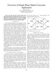
Active load <strong>with</strong> a small filter capacitor of 10 µF<br />
was considered. The value of leakage inductance<br />
(L lk = 4.8 µH) was obtained experimentally, by<br />
measuring the transformers mutual and selfinductances.<br />
It can also be noted, that the <strong>converter</strong><br />
operates as desired, providing 400 V output voltage<br />
at rated input and load conditions and that the<br />
transistor voltage does not exceed the maximum<br />
allowed voltage of main power transistor 300 V and<br />
maximum allowed current 73 A.<br />
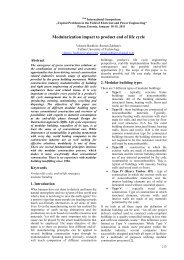
The schematic of DIC <strong>converter</strong> <strong>with</strong> active<br />
clamping circuit in LTspice environment and<br />
simulation results for the active clamping topology<br />
are presented in Fig. 8. and Fig. 9. It can be noted<br />
that the shape of the auxiliary switch current is<br />
determined by the resonant circuit formed by the L lk<br />
and C clamp .<br />
4 Experimental results<br />
Experimental testing of active clamping DIC<br />
<strong>converter</strong> was carried out as well. The testing was<br />
performed using Ballard Nexa PEM fuel cell module<br />
<strong>with</strong> nominal power 1.2 kW and connecting the DIC<br />
<strong>converter</strong> to a resistive load. Measurements of the<br />
input current, input voltage and load voltage and<br />
current were done. Then the efficiency of the<br />
<strong>converter</strong> was calculated. The efficiency of the DIC<br />
<strong>converter</strong> <strong>with</strong> the active clamping circuit is around<br />
93 % (Table 1.)<br />
Table 1. The Measured Quantities<br />
Parameter (averal values) Measurements<br />
Vin<br />
26.7 V<br />
Vout<br />
336 V<br />
Iin<br />
28.73 A<br />
Iout<br />
2.12 A<br />
Efficiency 93 %<br />
Faster diodes (better turn-on and turn-off<br />
characteristics than integrated diodes in transistors)<br />
and 2.2 nF capacitors were added in parallel <strong>with</strong><br />
active clamping transistors. In parallel <strong>with</strong> the<br />
power transistors, RC snubber circuits were<br />
implemented composed of 4.7 nF polyester film<br />
capacitors and 4.7 Ω 5 W resistors. Basing on<br />
equation (3) the capacitance of the clamping<br />
capacitor was 3.3 µF.<br />
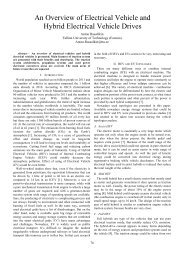
Experimental waveforms of the DIC <strong>converter</strong> <strong>with</strong><br />
the active clamping circuit are shown in Fig. 10. It<br />
was possible to test <strong>converter</strong> at the full load as there<br />
was no primary switch overvoltage problems.<br />
Fig. 8. DIC Converter schematics <strong>with</strong> Active<br />
Clamping Circuit in LTSpice environment<br />
Fig. 10. Experimental waveforms of the DIC<br />
<strong>converter</strong> <strong>with</strong> the active clamping – from the top:<br />
voltage across one active clamping tranzistor,<br />
voltage across one power transistor<br />
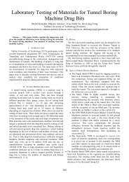
Fig. 9. Simulated waveforms of the DIC <strong>converter</strong><br />
<strong>with</strong> active clamping circuit: from the top – current<br />
through transistor M1, output voltage, voltage of the<br />
clamp capacitor, transformer primary voltage<br />
From the Fig. 11. it can be noticed that the load<br />
variation does not change the output voltage of the<br />
<strong>converter</strong> considerably. The following can be<br />
concluded, that the <strong>closed</strong> loop control system works<br />
as it changes the duty-cycle depending on the load<br />
and the output voltage remains constant.<br />
159