Current-fed double inductor push-pull DC/DC converter with closed ...
Current-fed double inductor push-pull DC/DC converter with closed ...
Current-fed double inductor push-pull DC/DC converter with closed ...

Create successful ePaper yourself
Turn your PDF publications into a flip-book with our unique Google optimized e-Paper software.
10 th International Symposium<br />
„Topical Problems in the Field of Electrical and Power Engineering“<br />
Pärnu, Estonia, January 10-15, 2011<br />
<strong>Current</strong>-<strong>fed</strong> <strong>double</strong> <strong>inductor</strong> <strong>push</strong>-<strong>pull</strong> <strong>DC</strong>/<strong>DC</strong> <strong>converter</strong> <strong>with</strong> <strong>closed</strong><br />
loop control system<br />
Aleksandrs Andreičiks, Ingars Steiks, Kristaps Vitols, Leonids Ribickis<br />
Riga Technical University<br />
aleksandrs.andreiciks@inbox.lv, ingars.steiks@rtu.lv, ktx@inbox.lv, leonids.ribickis@rtu.lv<br />
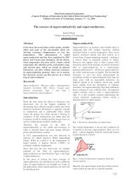
Abstract<br />
In order to use hydrogen fuel cells in domestic<br />
applications either as main power supply or backup<br />
source, their low <strong>DC</strong> output voltage has to be<br />
matched to the level and frequency of the utility<br />
grid AC voltage. Such power <strong>converter</strong> systems<br />
usually consist of a <strong>DC</strong>-<strong>DC</strong> <strong>converter</strong> and a <strong>DC</strong>-<br />
AC inverter. A <strong>double</strong> <strong>inductor</strong> step-up <strong>push</strong>-<strong>pull</strong><br />
<strong>converter</strong> <strong>with</strong> the output voltage and the input<br />
current control is investigated in this paper,<br />
presenting simulation and experimental results for<br />
passive and active overvoltage clamping. The<br />
prototype of the investigated <strong>converter</strong> is elaborated<br />
for 1200 W power to match the rated power of the<br />
proton exchange membrane (PEM) fuel cell<br />
located in hydrogen fuel cell research laboratory.<br />
Keywords<br />
Fuel cell system, high frequency power <strong>converter</strong>s,<br />
ZVS <strong>converter</strong>s<br />
groups – voltage source <strong>converter</strong>s and current <strong>fed</strong><br />
<strong>converter</strong>s. In this paper a current <strong>fed</strong> topology is<br />
preferred, since it is characterized by low input<br />
current ripple, which is more appropriate for proton<br />
exchange membrane fuel cells modules [3],[4].<br />
.Considering the necessity of high voltage boosting<br />
function <strong>with</strong> low input current ripple, the most<br />
appropriate <strong>converter</strong>s are current <strong>fed</strong> full-bridge<br />
and <strong>push</strong>-<strong>pull</strong> configurations. Since the <strong>converter</strong><br />
efficiency can be considerably improved by<br />
reducing the count of the primary switches and<br />
implementing a transformer of a simple structure<br />
(<strong>with</strong>out split windings), a <strong>double</strong> <strong>inductor</strong> <strong>push</strong>-<strong>pull</strong><br />
<strong>converter</strong> (DIC) was selected and analyzed in this<br />
paper Fig. 1. The <strong>converter</strong> is elaborated for 1200 W<br />
power, since such is the rated power of the proton<br />
exchange membrane (PEM) fuel cell in hydrogen<br />
fuel cell research laboratory of Riga Technical<br />
University.<br />
Introduction<br />
The research of the hydrogen energy has gained a<br />
growing interest in the recent years. The hydrogen<br />
fuel cells are fully ecological, taking into account<br />
that heat and water are the only by-products, which<br />
are excreted into the environment [1]. In order to<br />
utilize the electrical energy, produced by fuel cells,<br />
characterized by slow dynamic response, low output<br />
voltage and large voltage variations, static power<br />
<strong>converter</strong>s are researched widely.<br />
The fuel cells used as main power supply or backup<br />
source in domestic application need to be connected<br />
to the grid. Such power <strong>converter</strong> systems usually<br />
consist of a <strong>DC</strong>-<strong>DC</strong> <strong>converter</strong> and a <strong>DC</strong>-AC<br />
<strong>converter</strong>. Because of comparatively high input and<br />
output voltage difference, most frequently as the<br />
optimal solution <strong>converter</strong>s <strong>with</strong> high frequency<br />
transformer are acknowledged for the <strong>DC</strong>-<strong>DC</strong> stage<br />
[1]-[4]. There are many known transformer isolated<br />
dc-dc <strong>converter</strong> topologies, which could be suitable<br />
to perform the necessary voltage boost from the fuel<br />
cell voltage level to the inverter dc link voltage.<br />
Such <strong>converter</strong>s are the full-bridge, half-bridge, the<br />
flyback, the forward and the <strong>push</strong>-<strong>pull</strong> basic<br />
topologies, as well as a number of their derived<br />
topologies [5], [6]. These can be divided into two<br />
Fig. 1. <strong>Current</strong> <strong>fed</strong> <strong>double</strong> <strong>inductor</strong> <strong>push</strong>-<strong>pull</strong><br />
<strong>converter</strong> topology<br />
The hard switching <strong>converter</strong>s have a drawback of<br />
voltage overshoots at turn-off due to the energy<br />
stored in the parasitic inductances. These voltage<br />
spikes are not only dangerous to the transistors but<br />
they substantially increase the switching losses.<br />
There are two basic ways to protect the transistor<br />
switches from being damaged by the overvoltage.<br />
The first is using transistors <strong>with</strong> blocking voltage<br />
ratings that exceed these stresses. This, however,<br />
results in poor utilization of the transistors, since on<br />
state resistance of the MOSFET transistors increases<br />
dramatically <strong>with</strong> increased blocking voltage.<br />
1 Control of the <strong>converter</strong><br />
To control the designed <strong>converter</strong> it will be<br />
compared two control types, the duty-cycle and the<br />
current control. In all switching <strong>converter</strong>s, the<br />
output voltage is desired to be kept constant, in<br />
156
despite of the disturbances in the <strong>converter</strong> element<br />
values, or inputs. For this, a control system is needed<br />
which can automatically adjust the duty cycle as<br />
necessary to keep constant the output voltage <strong>with</strong>in<br />
an acceptable range, regardless of the load current or<br />
input changes. [5]<br />
Two types of control for the DIC <strong>push</strong>-<strong>pull</strong> boost<br />
<strong>converter</strong>, the direct duty-cycle control and the<br />
current control. In the following will be briefly<br />
described both of them, enumerating some<br />
advantages and disadvantages for each. Basic<br />
scheme is depicted by Fig. 2.<br />
Fig. 2. Control of the <strong>converter</strong><br />
1.1 Duty Cycle control<br />
In duty-cycle control model the output voltage is<br />
measured and then compared to the reference<br />
voltage. The error signal is used as input in the<br />
compensator, which will compute from it the dutycycle<br />
reference for the pulse-width modulator. Its<br />
principle is illustrated Fig. 3.<br />
Fig. 3. Direct duty-cycle control scheme<br />
1.2. <strong>Current</strong> control<br />
In current control model the <strong>converter</strong> output is<br />
controlled by choice of the transistor peak current.<br />
The control signal is a current and a simple control<br />
network switches on and off the transistor such its<br />
peak current follows the control input.<br />
In the literature [5] and [6] is stated that the current<br />
control, in the case of an isolated boost <strong>push</strong>-<strong>pull</strong><br />
<strong>converter</strong> has some advantages against the dutycycle<br />
control. First, it has simpler dynamics<br />
(removes one pole from the control-to output<br />
transfer function). Second, it makes use of the<br />
current sensor information in normal operation mode<br />
– transistor failures due to excessive currents can be<br />
prevented by limiting the reference switch current.<br />
In the transformer can be induced a dc bias current<br />
by small voltage imbalances due to the small<br />
differences in boost <strong>inductor</strong>s and/or switches.<br />
The current control will alter the switch duty cycles<br />
in a way that these imbalances tend to disappear and<br />
the transformer volt-second balance to be<br />
maintained.<br />
The disadvantage is that the current control has a<br />
susceptibility to noise in the reference and measured<br />
switch current signals. In general, a small amount of<br />
filtering is necessary for the measured current. The<br />
current control becomes unstable whenever the dutycycle<br />
becomes larger than 0.5. This drawback can be<br />
overcome by adding an artificial ramp to the<br />
reference current signal.<br />
Considering the above arguments, the current<br />
control seems to be more attractive for the present<br />
application.<br />
1.3 The current controlled <strong>converter</strong> model<br />
Evaluating the model of the current controller<br />
implies the calculation of the relation between the<br />
<strong>inductor</strong> current and the control signal Fig. 4. In our<br />
case there are two <strong>inductor</strong>s and in the relation will<br />
be used the sum of these two <strong>inductor</strong> currents.<br />
Fig.4. <strong>Current</strong> control scheme<br />
Is a known problem of the current control that it<br />
becomes unstable when the duty cycle passes by 0.5.<br />
The addition of an artificial ramp to the sensed<br />
signal can improve the stability of the controller, and<br />
for an adequate slope, it can be stable for all dutycycles.<br />
However, in the present case the maximum<br />
duty-cycle is 0.5, thereby only a small slope is<br />
required, to improve the noise immunity of the<br />
system. This small slope will not influence the<br />
<strong>converter</strong> transfer functions and controller design.<br />
The most important are that: it keeps the input<br />
current under a desired value and it realizes the<br />
current balance between positive and negative<br />
alternance in the high frequency transformer<br />
preventing the saturation of the transformer core.<br />
The measured signals are the fuel cell voltage (VFC)<br />
and current (IFC) and the output voltage (V<strong>DC</strong>)<br />
Fig. 5. The fuel cell current (IFC) and output voltage<br />
(V<strong>DC</strong>) are used as feedback signals in control.<br />
The protection is realized by using all the measured<br />
signals.<br />
The voltages V<strong>DC</strong> and VFC are measured by means<br />
of resistive voltage dividers while the fuel cell<br />
current (input current) is measured <strong>with</strong> a current<br />
transducer (LEM).<br />
157
FC<br />
VFC<br />
L1<br />
L2<br />
S1a<br />
G1a<br />
S2a<br />
G2a<br />
1:n<br />
D1<br />
D2<br />
D3<br />
D4<br />
C<br />
V<strong>DC</strong><br />
R<br />
Load<br />
i L1<br />
L1<br />
L2<br />
Llk<br />
i S<br />
+<br />
1:n D1 D3<br />
i C i R<br />
V P<br />
V S<br />
C R<br />
V <strong>DC</strong><br />
G1<br />
S1<br />
Cclamp<br />
S2<br />
G2<br />
Sa1<br />
Sa2<br />
D2<br />
D4<br />
V<strong>DC</strong>ref<br />
+<br />
-<br />
V<strong>DC</strong>m<br />
iFC/2 = iin<br />
Voltage iFC/2ref<br />
controller<br />
iFC/2m<br />
<strong>Current</strong><br />
controller<br />
OUT1<br />
OUT2<br />
CLK<br />
EN<br />
Gate signal<br />
conditioning<br />
G1<br />
G2<br />
G1a<br />
G2a<br />
i L2<br />
i FC<br />
Da1<br />
Ca1<br />
D1<br />
Da2<br />
Ca2<br />
D2<br />
C clamp<br />
V FC C1<br />
C2<br />
S1 S2<br />
-<br />
V<strong>DC</strong>m<br />
iFC/2m<br />
PROTECTION<br />
FAULT<br />
VFCm<br />
Fig. 5. DIC Converter schematics and control block<br />
diagram<br />
Experimental set-up of the control board was<br />
fulfilled by the Field-Programmable-Gate-Array<br />
(FPGA). Flowchart of the FPGA’s program is<br />
illustrated in general by Fig. 6. It should be<br />
mentioned that the voltage-to-frequency integrated<br />
circuit was used at the FPGA’s input, as it generates<br />
related square-wave signal <strong>with</strong> defined frequency<br />
depending on the input voltage. The control system<br />
was tuned so that 100 kHz square-wave signal is at<br />
FPGA’s input related to the nominal output voltage<br />
of the DIC <strong>converter</strong>.<br />
Start<br />
Fig. 7. <strong>Current</strong>-<strong>fed</strong> DIC Converter <strong>with</strong> Active<br />
Clamping Circuit<br />
commanded in anti-phase to the main switches. The<br />
basis of the operation of the presented clamping<br />
circuit is the resonant phenomena between the<br />
leakage inductance of the transformer (L lk ) and the<br />
clamping capacitor (C clamp ). The value of C clamp<br />
should be set so that one half of the resonant period<br />
formed by C clamp and L lk exceeds the maximum turnoff<br />
time of the main switches. [4] The clamping<br />
capacitor value is<br />
2 2 2<br />
clamp > s (1 − ) π ⋅ lk<br />
C T D L<br />
. (1)<br />
Yes<br />
Set default values<br />
Do not change duty<br />
cycle<br />
Yes<br />
To achieve ZVS for the main switch, it must be<br />
turned on after turn-off the auxiliary switch. This<br />
delay should be selected to be less than one quarter<br />
of the resonant period formed by L lk and C 1<br />
capacitor [4]<br />
Is the duty cycle =<br />
min?<br />
No<br />
Decrease the duty<br />
cycle<br />
Yes<br />
Yes<br />
Is Vdc_output ><br />
Vdc_ref?<br />
No<br />
Is the duty cycle =<br />
max?<br />
No<br />
Is the input current<br />
= max?<br />
No<br />
T L C π<br />
M 1− M 1a =<br />
lk<br />
⋅<br />
1<br />
⋅ 2<br />
, (2)<br />
where the value for C 1 has been taken from the<br />
datasheet of the chosen switch. The maximum time<br />
delay between turning off the main switch and<br />
turning on the auxiliary, using the calculated<br />
minimum value for the clamping capacitor can be<br />
considered by<br />
Set the new value<br />
of the duty cycle<br />
Increase the duty<br />
cycle<br />
T L C π<br />
M 1− M 1a =<br />
lk<br />
⋅<br />
clamp<br />
⋅ 2<br />
. (3)<br />
Fig. 6. Flowchart of the program implemented in<br />
FPGA.<br />
2 <strong>Current</strong>-<strong>fed</strong> DIC <strong>converter</strong> <strong>with</strong> active<br />
clamping circuit<br />
A DIC <strong>converter</strong> <strong>with</strong> active clamping circuit is<br />
shown on Fig. 7. In this case, the energy from the<br />
leakage inductance is not dissipated on the clamping<br />
resistance but transferred to the output. The active<br />
clamping circuit can improve the efficiency of the<br />
<strong>converter</strong>, as it does not dissipate the leakage<br />
<strong>inductor</strong> energy on a resistance but feeds it to the<br />
transformer primary. With active clamping circuit it<br />
is able to operate at ZVS both at turn-on and turn-off<br />
for all switches and simple to implement as it<br />
contains only a capacitor and two transistors<br />
3 Simulation of the DIC <strong>converter</strong><br />
The simulation of the DIC <strong>converter</strong> was done using<br />
LTspice simulation tool. Since a steady operation<br />
point was to be examined, the FC was modelled by a<br />
constant voltage source. The core losses of the<br />
inductances were neglected. The transformer was<br />
modelled as an ideal transformer introducing the<br />
leakage inductance in series. The power MOSFET<br />
transistor switches (IXFN73N30) and active<br />
clamping MOSFET transistors (IRF740) were<br />
modelled using SPICE models provided by the<br />
manufacturers.<br />
The operation conditions of the simulation are<br />
adjusted to the rated parameters of the <strong>converter</strong>.<br />
158
Active load <strong>with</strong> a small filter capacitor of 10 µF<br />
was considered. The value of leakage inductance<br />
(L lk = 4.8 µH) was obtained experimentally, by<br />
measuring the transformers mutual and selfinductances.<br />
It can also be noted, that the <strong>converter</strong><br />
operates as desired, providing 400 V output voltage<br />
at rated input and load conditions and that the<br />
transistor voltage does not exceed the maximum<br />
allowed voltage of main power transistor 300 V and<br />
maximum allowed current 73 A.<br />
The schematic of DIC <strong>converter</strong> <strong>with</strong> active<br />
clamping circuit in LTspice environment and<br />
simulation results for the active clamping topology<br />
are presented in Fig. 8. and Fig. 9. It can be noted<br />
that the shape of the auxiliary switch current is<br />
determined by the resonant circuit formed by the L lk<br />
and C clamp .<br />
4 Experimental results<br />
Experimental testing of active clamping DIC<br />
<strong>converter</strong> was carried out as well. The testing was<br />
performed using Ballard Nexa PEM fuel cell module<br />
<strong>with</strong> nominal power 1.2 kW and connecting the DIC<br />
<strong>converter</strong> to a resistive load. Measurements of the<br />
input current, input voltage and load voltage and<br />
current were done. Then the efficiency of the<br />
<strong>converter</strong> was calculated. The efficiency of the DIC<br />
<strong>converter</strong> <strong>with</strong> the active clamping circuit is around<br />
93 % (Table 1.)<br />
Table 1. The Measured Quantities<br />
Parameter (averal values) Measurements<br />
Vin<br />
26.7 V<br />
Vout<br />
336 V<br />
Iin<br />
28.73 A<br />
Iout<br />
2.12 A<br />
Efficiency 93 %<br />
Faster diodes (better turn-on and turn-off<br />
characteristics than integrated diodes in transistors)<br />
and 2.2 nF capacitors were added in parallel <strong>with</strong><br />
active clamping transistors. In parallel <strong>with</strong> the<br />
power transistors, RC snubber circuits were<br />
implemented composed of 4.7 nF polyester film<br />
capacitors and 4.7 Ω 5 W resistors. Basing on<br />
equation (3) the capacitance of the clamping<br />
capacitor was 3.3 µF.<br />
Experimental waveforms of the DIC <strong>converter</strong> <strong>with</strong><br />
the active clamping circuit are shown in Fig. 10. It<br />
was possible to test <strong>converter</strong> at the full load as there<br />
was no primary switch overvoltage problems.<br />
Fig. 8. DIC Converter schematics <strong>with</strong> Active<br />
Clamping Circuit in LTSpice environment<br />
Fig. 10. Experimental waveforms of the DIC<br />
<strong>converter</strong> <strong>with</strong> the active clamping – from the top:<br />
voltage across one active clamping tranzistor,<br />
voltage across one power transistor<br />
Fig. 9. Simulated waveforms of the DIC <strong>converter</strong><br />
<strong>with</strong> active clamping circuit: from the top – current<br />
through transistor M1, output voltage, voltage of the<br />
clamp capacitor, transformer primary voltage<br />
From the Fig. 11. it can be noticed that the load<br />
variation does not change the output voltage of the<br />
<strong>converter</strong> considerably. The following can be<br />
concluded, that the <strong>closed</strong> loop control system works<br />
as it changes the duty-cycle depending on the load<br />
and the output voltage remains constant.<br />
159
integrated circuit, for a current <strong>fed</strong> <strong>converter</strong> implies<br />
new problems, as the signal conditioning in order to<br />
realize the overlapping of the gate signals. However,<br />
using dedicated PWM controllers have important<br />
advantages as soft start-up and built-in over-current<br />
protection.<br />
References<br />
Fig. 11. Experimental waveforms of the DIC<br />
<strong>converter</strong> <strong>with</strong> the active clamping – from the top:<br />
output voltage, output current.<br />
Conclusions<br />
The power <strong>converter</strong> needed in order to use the<br />
hydrogen fuel cell as a main power supply or backup<br />
source in domestic applications, usually consists of a<br />
step-up <strong>DC</strong>/<strong>DC</strong> stage and a <strong>DC</strong>/AC inverter stage.<br />
As an efficient solution for the <strong>DC</strong>/<strong>DC</strong> stage – a<br />
<strong>double</strong> <strong>inductor</strong> <strong>push</strong> <strong>pull</strong> <strong>converter</strong> <strong>with</strong> active<br />
voltage clamping circuit is analyzed in this paper<br />
presenting simulation and experimental results.<br />
It was acknowledged that the DIC <strong>converter</strong> <strong>with</strong><br />
active clamping circuit performs well and the<br />
efficiency of the <strong>converter</strong> is 93 %. The efficiency<br />
could be further increased basically in two ways: by<br />
decreasing the resistance of the <strong>converter</strong>’s primary<br />
circuit components or by reducing the primary<br />
current, which can be achieved by connecting two or<br />
more identical <strong>converter</strong>s in parallel.<br />
The ripple of the input current of the experimental<br />
prototype is below ± 5 % of the mean value, which<br />
is <strong>with</strong>in acceptable limits for the fuel cell.<br />
The elaborated prototype of <strong>double</strong> <strong>inductor</strong> <strong>push</strong><strong>pull</strong><br />
<strong>DC</strong>/<strong>DC</strong> <strong>converter</strong> <strong>with</strong> active clamping circuit<br />
can be used as a background for further work on<br />
clamp circuit optimization and the hardware<br />
implementation of the control, using a dedicated<br />
1. EGG Services Parsons Inc., “Fuel cell handbook<br />
(6th edition)”, United States Department of<br />
Energy, USA, November 2002.<br />
2. G. Gentile, S. Meo, F. Esposito, “Comparison<br />
Among Different Topologies of <strong>DC</strong>-<strong>DC</strong><br />
Converter for Fuel-Cell-Based Inverter System”,<br />
EPE-PEMC2004, Riga, Latvia, September 2004.<br />
3. W. Choi, P.N. Enjeti, J. W. Howze, G. Joung, “An<br />
experimental evaluation of the effects of ripple<br />
current generated by the power conditioning stage<br />
on a proton exchange membrane fuel cell stack”,<br />
Journal of Materials Engineering and<br />
Performance, New York, USA, Vol. 13.<br />
pp. 257-264, 2004.<br />
4. S. De Caro, A. Testa, D. Triolo, M. Cacciato, A.<br />
Consoli, “Low Input <strong>Current</strong> Ripple Converters<br />
for Fuel Cell Power Units// in Proc. Hard<br />
Switching Converters and Control EPE 2005. –<br />
Germany, 2005.<br />
5. N. Mohan, T. Undeland, W.P. Robbins, “Power<br />
Electronics. Converters, Applications and<br />
Design”, John Wiley & Sons,<br />
ISBN: 0-471-22693-9, 2003.<br />
6. R.W. Erickson, D. Maksimovic, “Fundamentals of<br />
Power Electronics”, Chapman & Hall,<br />
ISBN 0-7923-7270-0, 2001.<br />
7. J.T. Kim, B.K. Lee, T.W. Lee, S.J. Jang, S.S.<br />
Kim, C.Y. Won, “An Active Clamping <strong>Current</strong>-<br />
Fed Half-Bridge Converter for Fuel-Cell<br />
Generation Systems”, 35th Annual IEEE Power<br />
Electronics Specialists Conference, Aachen,<br />
Germany, 2004.<br />
8. F.J. Nome, I. Barbi, “A ZVS Clamping Mode -<br />
<strong>Current</strong>-Fed Push-<strong>pull</strong> <strong>DC</strong>-<strong>DC</strong> Converter”, IEEE,<br />
1998<br />
160