SEL-24-02 - Cessna
SEL-24-02 - Cessna
SEL-24-02 - Cessna

You also want an ePaper? Increase the reach of your titles
YUMPU automatically turns print PDFs into web optimized ePapers that Google loves.
Single<br />
Engine<br />
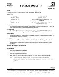
TITLE<br />
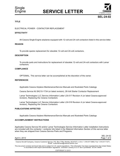
SERVICE LETTER<br />
<strong>SEL</strong>-<strong>24</strong>-<strong>02</strong><br />
ELECTRICAL POWER - CONTACTOR REPLACEMENT<br />
EFFECTIVITY<br />
REASON<br />
All <strong>Cessna</strong> Single Engine airplanes equipped with 12-volt and <strong>24</strong>-volt contactors listed in this service letter.<br />
To provide spares replacement for obsolete 12-volt and <strong>24</strong>-volt contactors.<br />
DESCRIPTION<br />
To provide parts and instructions for replacement of obsolete 12-volt and <strong>24</strong>-volt contactors with Lamar<br />
contactors.<br />
COMPLIANCE<br />
OPTIONAL. This service letter can be accomplished at the discretion of the owner.<br />
REFERENCES<br />
Applicable <strong>Cessna</strong> Airplane Maintenance/Service Manuals and Illustrated Parts Catalogs<br />
<strong>Cessna</strong> Service Kit SK210-173A (or latest revision), 28-Volt Starter Contactor Replacement<br />
Lamar Technologies LLC Service Information Letter LSI-017 Revision A (or latest <strong>Cessna</strong>-approved<br />
revision), Replacing the <strong>Cessna</strong> Contactors<br />
Lamar Technologies LLC Service Information Letter LSI-018 Revision A (or latest <strong>Cessna</strong>-approved<br />
revision), Replacing the <strong>Cessna</strong> Contactors<br />
PUBLICATIONS AFFECTED<br />
Applicable <strong>Cessna</strong> Airplane Maintenance/Service Manuals and Illustrated Parts Catalogs<br />
ACCOMPLISHMENT INSTRUCTIONS<br />
Applicable <strong>Cessna</strong> Service Kit and/or Lamar Technologies Service Information Letter installation instructions<br />
are included with the contactor / contactor kits listed in the Material Information Section of this service letter<br />
when they are shipped from <strong>Cessna</strong> Service Parts and Programs.<br />
April 4, 2013<br />
<strong>SEL</strong>-<strong>24</strong>-<strong>02</strong><br />
Page1of2<br />
<strong>Cessna</strong> Aircraft Company, <strong>Cessna</strong> Customer Service, P.O. Box 7706, Wichita, KS 67277, U.S.A. 1-316-517-5800, Fax 1-316-517-7271,<br />
Email: customercare@cessna.textron.com<br />
This document contains technical data and is subject to U.S. export regulations. This information has been exported from the United States<br />
in accordance with export administration regulations. Diversion contrary to U.S. law is prohibited. ECCN: 9A991<br />
COPYRIGHT © 2013
Single<br />
Engine<br />
SERVICE LETTER<br />
<strong>SEL</strong>-<strong>24</strong>-<strong>02</strong><br />
MATERIAL INFORMATION<br />
NEW P/N<br />
INSTALLATION<br />
INSTRUC-<br />
TIONS<br />
P52-0016 SK210-173A Contactor Kit, <strong>24</strong>V<br />
Intermittent Duty<br />
X61-0030 Not Required/<br />
Direct<br />
Replacement<br />
KEY WORD OLD P/N INSTRUCTIONS/<br />
DISPOSITION<br />
Contactor, 12V<br />
Intermittent Duty<br />
P52-0033 LSI-018, Rev A Contactor Kit, 12V<br />
Intermittent Duty<br />
P52-0034 LSI-018, Rev A Contactor Kit, 12V<br />
Continuous Duty<br />
P52-0034-1 LSI-017, Rev A Contactor Kit, 12V<br />
Continuous Duty<br />
P52-0035-1 LSI-017, Rev A Contactor Kit, <strong>24</strong>V<br />
Continuous Duty<br />
S1577-1, S1577A1,<br />
8781-8<br />
S2103-1, S2103A1,<br />
111-139D<br />
S1991-1, S1991A1,<br />
111-138D, SAW4204-1,<br />
SAW4206-1<br />
S1660-1, S1660A1,<br />
8781-10<br />
S1579-1, S1579-2,<br />
S1579A2, 111-140D<br />
S1580-1, S1580A1,<br />
8781-9<br />
Discard<br />
Discard<br />
Discard<br />
Discard<br />
Discard<br />
Discard<br />
<strong>SEL</strong>-<strong>24</strong>-<strong>02</strong><br />
Page 2 April 4, 2013
Single<br />
Engine<br />
OWNER ADVISORY<br />
<strong>SEL</strong>-<strong>24</strong>-<strong>02</strong><br />
TITLE<br />
ELECTRICAL POWER - CONTACTOR REPLACEMENT<br />
TO:<br />
<strong>Cessna</strong> <strong>Cessna</strong> Single Engine Classic Owner<br />
REASON<br />
This owner advisory is to inform you that <strong>SEL</strong>-<strong>24</strong>-<strong>02</strong> has been issued.<br />
<strong>SEL</strong>-<strong>24</strong>-<strong>02</strong> provides provide parts and instructions for replacement of obsolete 12-volt and <strong>24</strong>-volt<br />
contactors with Lamar contactors.<br />
COMPLIANCE<br />
OPTIONAL. This service letter can be accomplished at the discretion of the owner.<br />
LABOR HOURS<br />
Not applicable<br />
WARRANTY<br />
Not Applicable<br />
NOTE: As a convenience, service documents are now available online to all our customers through a<br />
simple, free-of-charge registration process. If you would like to sign up, please visit the "Customer<br />
Access" link at www.cessnasupport.com to register.<br />
This owner advisory will not be mailed to airplane owners. It is provided as an attachment to this service letter.<br />
April 4, 2013<br />
<strong>SEL</strong>-<strong>24</strong>-<strong>02</strong><br />
Page1of1<br />
<strong>Cessna</strong> Aircraft Company, <strong>Cessna</strong> Customer Service, P.O. Box 7706, Wichita, KS 67277, U.S.A. 1-316-517-5800, Fax 1-316-517-7271,<br />
Email: customercare@cessna.textron.com<br />
This document contains technical data and is subject to U.S. export regulations. This information has been exported from the United States<br />
in accordance with export administration regulations. Diversion contrary to U.S. law is prohibited. ECCN: 9A991<br />
COPYRIGHT © 2013
Single Engine<br />
SERVICE KIT<br />
SK210-173A<br />
TITLE<br />
28-VOLT STARTER CONTACTOR REPLACEMENT<br />
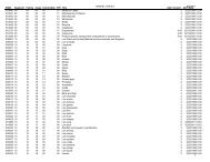
EFFECTIVITY<br />
Model Year Serial Numbers<br />
152 1978 15279406 thru 15282031<br />
152 1979 15282032 thru 15283591<br />
A152 1978 A1520735 thru A1520808<br />
A152 1979 A1520809 thru A1520878<br />
172N 1978 17269310 thru 17270049<br />
172N 1978 17270051 thru 17271034<br />
172N 17261578<br />
172N 1979 17271035 thru 17272884<br />
R172E (T41) 1967 thru 1968 R172-0001 thru R172-0335<br />
R172F (T41) 1969 R172-0336 thru R172-0409<br />
R172G (T41) 1969 thru 1970 R1720410 thru R1720444<br />
R172H (T41) 1971 R1720445 thru R1720494<br />
R172H (T41) 1972 R1720495 thru R1720546<br />
R172H (T41) 1973 thru 1976 R1720547 thru R1720620<br />
R172K 1978 R1722725 thru R1722929<br />
R172K 1979 R1722930 thru R1723199<br />
177RG 1978 177RG1267 thru 177RG1366<br />
177RG<br />
177RG0419<br />
180K 1978 18052906 thru 18053000<br />
180K 1979 18053001 thru 18053082<br />
182Q 1978 18265966 thru 18266590<br />
182Q 1979 18266591 thru 18266977<br />
R182 1978 R182000<strong>02</strong> thru R18200583<br />
R182/TR182 1979 R18200584 thru R18201089<br />
A185F 1978 18503459 thru 18503683<br />
A185F 1979 18503684 thru 18503846<br />
October 1, 2009<br />
Original Issue: April 17, 2006 Page 1 of 5<br />
To obtain satisfactory results, procedures specified in this publication must be accomplished in accordance with accepted methods and<br />
prevailing government regulations. <strong>Cessna</strong> Aircraft Company cannot be responsible for the quality of work performed in accomplishing the<br />
requirements of this publication.<br />
<strong>Cessna</strong> Aircraft Company, Customer Service, P.O. Box 7706, Wichita, Kansas 67277, U.S.A. (316) 517-5800, Facsimile (316) 942-9006<br />
COPYRIGHT © 2006
SERVICE KIT<br />
SK210-173A<br />
A188B 1976 188<strong>02</strong>349 thru 188<strong>02</strong>745<br />
A188B 1977 188<strong>02</strong>746 thru 18803046<br />
A188B 1978 18803047 thru 18803296<br />
A188B 1979 18803297 thru 18803472<br />
A188B 1979 18803297T thru 18803472T<br />
FR172K 1978 FR17200621 thru FR17200630<br />
FR172K 1979 FR17200631 thru FR17200655<br />
U206F/TU206F 1974 U206<strong>02</strong>200 thru U206<strong>02</strong>579<br />
U206F/TU206F 1975 U206<strong>02</strong>580 thru U206<strong>02</strong>588<br />
U206F/TU206F 1975 U206<strong>02</strong>590 thru U20603<strong>02</strong>0<br />
U206F/TU206F 1976 U20603<strong>02</strong>1 thru U20603521<br />
U206G/TU206G 1977 U20603522 thru U20604074<br />
U206G/TU206G 1978 U20604075 thru U20604649<br />
U206G/TU206G 1979 U20604650 thru U20605080<br />
U206G/TU206G<br />
U206<strong>02</strong>589<br />
207/T207 1974 2070<strong>02</strong>28 thru 2070<strong>02</strong>67<br />
207/T207 1975 2070<strong>02</strong>68 thru 20700314<br />
207/T207 1976 20700315 thru 20700362<br />
207A/T207A 1977 20700363 thru 20700414<br />
207A/T207A 1978 20700415 thru 20700482<br />
207A/T207A 1979 20700483 thru 20700538<br />
210L/T210L 1972 21059503 thru 21059719<br />
210L/T210L 1973 21059720 thru 21060089<br />
210L/T210L 1974 21060090 thru 21060539<br />
210L/T210L 1975 21060540 thru 21061039<br />
210L/T210L 1976 21061040 thru 21061041<br />
210L/T210L 1976 21061043 thru 21061573<br />
210M/T210M 1977 21061574 thru 21062273<br />
210M/T210M 1978 21062274 thru 21062954<br />
210M/T210M 1978 21061042<br />
210N/T210N 1979 21062955 thru 21063476<br />
P210N 1978 P21000001 thru P21000150<br />
P210N 1979 P21000151 thru P21000344<br />
F152 1978 F15201429 thru F15201528<br />
FA152 1978 FA1520337 thru FA1520347<br />
FA152 1979 FA1520348 thru FA1520357<br />
F172N 1978 F17201640 thru F17201749<br />
SK210-173A<br />
Page 2 October 1, 2009
SERVICE KIT<br />
SK210-173A<br />
F172N 1979 F17201750 thru F17201909<br />
F182Q 1978 F18200065 thru F18200094<br />
F182Q 1979 F18200095 thru F18200129<br />
FR182 1978 FR18200001 thru FR18200<strong>02</strong>0<br />
FR182 1979 FR18200<strong>02</strong>1 thru FR18200045<br />
FR182 1980 FR18200046 thru FR18200055<br />
DESCRIPTION<br />
Toprovideaspares replacement for the 28-volt starter contactor.<br />
APPROVAL<br />
FAA approval has been obtained on technical data in this publication that affects airplane type design.<br />
CHANGE IN WEIGHT AND BALANCE<br />
Negligible<br />
MATERIAL INFORMATION<br />
The part below covers installation for one airplane.<br />
NEW P/N QUANTITY DESCRIPTION OLD P/N DISPOSITION<br />
SK210-173A 1 Kit, consisting of the<br />
following parts:<br />
P52-0016 1 28-Volt Starter Contactor S1577-1,<br />
S1577A1,<br />
8781-8<br />
Discard<br />
1 Instructions<br />
ACCOMPLISHMENT INSTRUCTIONS<br />
1. Prepare the airplane for maintenance.<br />
A. Make sure that all switches are in the OFF/NORM position.<br />
B. Remove the upper engine cowl.<br />
C. Disconnect electrical power from the airplane.<br />
(1) Disconnect the airplane battery.<br />
(2) Disconnect external electrical power.<br />
D. Attach maintenance warning tags to the battery and external power receptacle that have "DO NOT<br />
CONNECT ELECTRICAL POWER - MAINTENANCE IN PROGRESS" writtenonthem.<br />
SK210-173A<br />
October 1, 2009 Page 3
SERVICE KIT<br />
SK210-173A<br />
CAUTION: Do not use the P52-0016 28-Volt Starter Contactor to replace contactors in the airplane<br />
other than those in the starter system. If you replace a contactor other than a starter<br />
contactor with the P52-0016 28-Volt Starter Contactor, damage to the equipment will occur.<br />
2. Get access to the 28-volt starter contactors on the left side of the forward engine firewall. (Refer to<br />
the applicable sections of the Service Manual.)<br />
NOTE: To find the contactors, follow the starter power cable from the starter to the contactor.<br />
3. (Refer to Figure 1.) Remove and discard the 28-volt starter contactor. Keep the hardware that attaches<br />
the starter contactor to the firewall. (Refer to the applicable sections of the Service Manual.)<br />
4. With the kept attachment hardware, install the new P52-0016 28-Volt Starter Contactor to the firewall.<br />
(Refer to the applicable sections of the Service Manual.)<br />
CAUTION: Make sure that you install the wires to the same terminal studs as shown in Figure<br />
1. If you install the wires in a different configuration than the one shown in Figure 1,<br />
damage to the system may occur.<br />
A. As you install the contactor, install the loose end of the ground wire that is attached to the contactor<br />
under one of the contactor mount bolts to provide a ground for the contactor coil.<br />
CAUTION: If the airplane has a diode wire, do not replace the diode wire with a standard<br />
ground wire. If you replace the diode wire with a standard ground wire, damage to<br />
the system may occur.<br />
CAUTION: If the airplane has a diode wire, do not install the diode wire on the same terminal<br />
stud with the ground wire. If you install the diode wire and the ground stud wire on the<br />
same terminal stud, damage to the system may occur.<br />
B. If the airplane has a diode wire, install it on the new starter contactor. Install it on a different terminal<br />
stud than the one on which the ground wire is installed.<br />
5. Install the upper engine cowl.<br />
6. Remove maintenance warning tags and connect the airplane battery.<br />
7. Make an entry in the airplane logbook stating this service kit has been installed.<br />
SK210-173A<br />
Page 4 October 1, 2009
SERVICE KIT<br />
SK210-173A<br />
Figure 1. 28-Volt Starter Contactor Replacement (Sheet 1)<br />
SK210-173A<br />
October 1, 2009 Page 5
<strong>Cessna</strong> Aircraft Company Proprietary Information<br />
CONTACTOR KITS<br />
Issued: 1/17/2013<br />
SERVICE INFORMATION LETTER<br />
REPLACING THE CESSNA CONTACTORS<br />
SUBJECT: This letter is to provide wiring installation instructions for Lamar P/N P52-0034-1 (12V<br />
Contactor kit) and Lamar P/N P52-0035-1 (<strong>24</strong>V Contactor kit) as a replacement for the<br />
<strong>Cessna</strong> P/N S1579 (12V) and S1580 (<strong>24</strong>V) contactors. These instructions shall be printed<br />
and distributed in the packaging with each contactor kit.<br />
REASON:<br />
To provide clarification of contactor terminal definition for installing on aircraft.<br />
INFORMATION: Reference Figure shown below. The Lamar contactor kit will come with a red jumper wire<br />
installed from the Battery Terminal to the Coil Power Terminal. This jumper shall convert a<br />
4 terminal contactor for replacement of a 3 terminal contactor. 3 terminal contactors (S1579<br />
and S1580) have this connection inside the contactor without a coil power terminal. Aircraft<br />
wiring must control (on or off) the contactor coil through the Coil Ground Terminal and not<br />
have any wires (except jumper) attached to the Coil Power Terminal.<br />
For technical support call <strong>Cessna</strong> Customer Care at 316-517-5800<br />
FIGURE:<br />
Coil Power Terminal<br />
(DO NOT connect<br />
aircraft wires here)<br />
Coil Ground<br />
Terminal<br />
Battery<br />
Terminal<br />
Load<br />
Terminal<br />
Red<br />
Jumper<br />
Wire<br />
LSI-017 REV: A RELEASE DATE: 1/17/13 PAGE 1 OF 1<br />
Printed On <strong>02</strong>/06/2013
<strong>Cessna</strong> Aircraft Company Proprietary Information<br />
CONTACTOR KITS<br />
Issued: 1/17/2013<br />
SERVICE INFORMATION LETTER<br />
REPLACING THE CESSNA CONTACTORS<br />
SUBJECT: This letter is to provide wiring installation instructions for Lamar P/N P52-0033 (12V<br />
Intermittent Duty Contactor kit) and Lamar P/N P52-0034 (12V Continuous Duty Contactor<br />
kit) as a replacement for the <strong>Cessna</strong> P/N S1991 (Intermittent Duty) and S1660 (Continuous<br />
Duty) contactors. These instructions shall be printed and distributed in the packaging with<br />
each contactor kit.<br />
REASON:<br />
To provide clarification of contactor terminal definition for installing on aircraft.<br />
INFORMATION: Reference Figure shown below. The Lamar contactor kit will come with a black jumper wire<br />
with one end installed on the Coil Ground Terminal. This jumper when connected to the<br />
airframe ground (as shown) shall convert a 4 terminal contactor for replacement of a 3<br />
terminal contactor. 3 terminal contactors (S1991 and S1660) have this connection inside<br />
the contactor without a Coil Ground Terminal. Aircraft wiring must control (on or off) the<br />
contactor coil through the Coil Power Terminal and not have any wires (except jumper)<br />
attached to the Coil Ground Terminal.<br />
For technical support call <strong>Cessna</strong> Customer Care at 316-517-5800<br />
FIGURE:<br />
Coil Ground Terminal<br />
(do not connect<br />
aircraft wires here)<br />
Coil Power<br />
Terminal<br />
Battery<br />
Terminal<br />
Load<br />
Terminal<br />
Black<br />
Jumper<br />
Wire<br />
LSI-018 REV: A RELEASE DATE: 1/17/13 PAGE 1 OF 1<br />
Printed On <strong>02</strong>/06/2013