GPS Patch Antenna Considerations - MRC Components
GPS Patch Antenna Considerations - MRC Components
GPS Patch Antenna Considerations - MRC Components

Create successful ePaper yourself
Turn your PDF publications into a flip-book with our unique Google optimized e-Paper software.
<strong>GPS</strong> <strong>Patch</strong> <strong>Antenna</strong> <strong>Considerations</strong><br />
Advanced Material On TECHnology
n <strong>Antenna</strong> Element<br />
Contents<br />
n Impedance and Resonant Frequency<br />
n Axial Ratio<br />
n Voltage Standing Wave Ratio (VSWR)<br />
n Bandwidth<br />
n Result of Measurement<br />
AMOTECH 2
<strong>Antenna</strong> Element<br />
n The antenna’s size and shape<br />
n compact size using ceramic material<br />
n RHCP(Right Hand Circular Polarization) patch<br />
Offset fed<br />
rectangular patch<br />
Slotted square<br />
patch<br />
Truncated corner<br />
square patch<br />
AMOTECH 3
<strong>Antenna</strong> Element<br />
n AMOTECH - <strong>GPS</strong> <strong>Patch</strong> <strong>Antenna</strong><br />
25<br />
25 4<br />
2.6<br />
0.5 3<br />
¥Õ0.8<br />
n compact size : 25mm × 25mm × 4mm<br />
n excellent temperature stability<br />
n (silver plated) truncated corner square patch<br />
¥Õ3.0<br />
AMOTECH 4
Impedance and Resonant Frequency<br />
n An antenna’s impedance depends on many factors :<br />
n how it is constructed,<br />
n how it is fed,<br />
n and to some degree, the surrounding environment<br />
n Amicrostrip patch antenna placed in a plastic enclosure<br />
(radome), for example, can have its resonant frequency<br />
shifted downward by several MHz, depending on<br />
n the thickness of the radome<br />
n its dielectric constant<br />
n and the distance between the antenna face and inner radome.<br />
AMOTECH 5
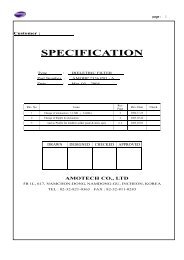
Impedance and Resonant Frequency<br />
n Radome effect on resonant frequency<br />
n Final Assembly<br />
AMOTECH<br />
<strong>GPS</strong> <strong>Patch</strong> <strong>Antenna</strong><br />
PCB<br />
Infinite Ground<br />
Sheild Can<br />
Infinite Ground<br />
70by70 Ground<br />
SMA Type<br />
Connector<br />
Radome<br />
Double Sided<br />
Adhesive Tape<br />
n Assembly without radome<br />
Return Loss [dB]<br />
0<br />
-5<br />
-10<br />
-15<br />
-20<br />
-25<br />
-30<br />
Frequency shift caused by<br />
radome<br />
different environment<br />
n <strong>Patch</strong> on 70 by 70 ground 1540 1550 1560 1570 1580 1590 1600 1610 1620 1630<br />
Frequency [MHz]<br />
The final assembly obtains optimized<br />
operation over 1575.42MHz ± 3MHz<br />
Final Assembly<br />
Assembly without Radome<br />
<strong>Patch</strong> on 70 by 70 GND<br />
AMOTECH 6
n General description<br />
Axial Ratio<br />
n To be maximally sensitive to <strong>GPS</strong> signals, the ideal <strong>GPS</strong><br />
antenna should be perfectly RHCP<br />
n The more elliptically polarized it is, the lower its RHCP<br />
sensitivity<br />
n The degree of ellipticity is given by the antenna’s axial ratio<br />
n Good <strong>GPS</strong> antennas have an axial ratio in the zenith direction<br />
of 3dB or better.<br />
n A measurement of the VSWR alone does not guarantee the<br />
antenna’s axial ratio performance.<br />
AMOTECH 7
n Measure the Axial Ratio<br />
n The <strong>GPS</strong> <strong>Patch</strong> antenna<br />
transmits at the desired<br />
frequency.<br />
n Rotates the linear<br />
polarization probe<br />
n AR = A - B , in dB<br />
B<br />
A<br />
Polarization<br />
ellipse<br />
¥è<br />
Axial Ratio<br />
n Measuring system in AMOTECH<br />
3 m<br />
Spectrum<br />
Analyzer<br />
rotate test<br />
probe<br />
7.26 m<br />
<br />
Signal<br />
Generator<br />
AMOTECH 8<br />
PC
Voltage Standing Wave Ratio<br />
n An important consideration is the antenna-receiver connection.<br />
This is achieved with a transmission line, usually a coaxial cable.<br />
n To maximize signal transfer from the antenna to the receiver, we<br />
must minimize power loss.<br />
n Power may be lost if the coupling between the antenna and the<br />
cable is imperfect and also within the cable itself.<br />
n To prevent power loss at the interface between the cable and the<br />
antenna, the impedance of the cable and the antenna must be the<br />
same.<br />
n The formula for relating mismatch loss to VSWR is:<br />
2<br />
⎛ ⎛ VSWR-1 ⎞ ⎞<br />
Mismatch_Loss(dB)=10log⎜1- ⎜ ⎜ ⎟ ⎟<br />
⎝VSWR+1⎠ ⎟<br />
⎝ ⎠<br />
AMOTECH 9
Bandwidth<br />
n Operating bandwidth is defined as frequency range<br />
satisfied following:<br />
n VSWR (< 2.0) or Return loss (< 10 dB)<br />
n Axial ratio (< 3.0 dB)<br />
n <strong>GPS</strong> patch antenna designed by AMOTECH satisfies<br />
all criteria over the operating frequency range of<br />
1575.42 MHz ± 3 MHz.<br />
AMOTECH 10
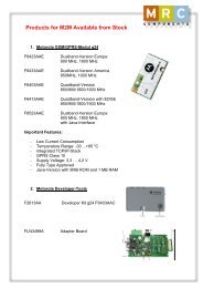
Result of Measurement<br />
n <strong>GPS</strong> <strong>Antenna</strong> installed on Infinite Ground<br />
Geometry of final assembly Axial Ratio<br />
AMOTECH<br />
<strong>GPS</strong> <strong>Patch</strong> <strong>Antenna</strong><br />
PCB<br />
Infinite Ground<br />
Sheild Can<br />
SMA Type<br />
Connector<br />
Radome<br />
Double Sided<br />
Adhesive Tape<br />
0<br />
1565 1570 1575 1580 1585<br />
AMOTECH 11<br />
Axialratio [dB]<br />
12<br />
10<br />
8<br />
6<br />
4<br />
2<br />
Frequency [MHz]
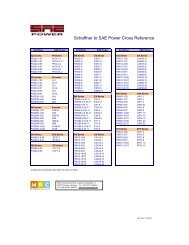
Result of Measurement<br />
n <strong>GPS</strong> <strong>Antenna</strong> installed on Infinite Ground<br />
CH1 S22 LOG 5 dB/ REF 0 dB<br />
PRm<br />
Cor<br />
Avg<br />
10<br />
Hld<br />
MARKER 1<br />
1.57542 GHz<br />
Return Loss Smith chart<br />
3 4<br />
17 May 2000 13:18:10<br />
CENTER 1. 575 000 000 GHz SPAN . 200 000 000 GHz<br />
1<br />
2<br />
1:-29 . 366 dB 1. 575 420 000 GHz<br />
CH1 Markers<br />
BW : . 019597108 GHz<br />
cent : 1. 576044505 GHz<br />
Q: 80 . 422<br />
1_ loss : -29 . 366 dB<br />
CH1 S22 1 U FS<br />
CENTER 1. 575 000 000 GHz SPAN . 200 000 000 GHz<br />
AMOTECH 12<br />
PRm<br />
Cor<br />
Avg<br />
10<br />
Hld<br />
MARKER 1<br />
1.57542 GHz<br />
1<br />
2<br />
17 May 2000 13:18:39<br />
1: 53 .414 -824 . 22 m 122 .57 pF 1. 575 420 000 GHz<br />
4<br />
3<br />
CH1 Markers<br />
2: 54 .098<br />
-304 .69 m<br />
1. 57604 GHz<br />
3: 95 .941<br />
-4 . 6016<br />
1. 56624 GHz<br />
4: 40 .080<br />
-28 . 146<br />
1. 58584 GHz
Result of Measurement<br />
n <strong>GPS</strong> <strong>Antenna</strong> installed on 70mm×70mm Ground<br />
CH1 S22 LOG 5 dB/ REF 0 dB<br />
PRm<br />
Cor<br />
Avg<br />
11<br />
Hld<br />
MARKER 1<br />
1.57604 GHz<br />
Return Loss Smith chart<br />
3 4<br />
2<br />
17 May 2000 13:20:18<br />
CENTER 1. 575 000 000 GHz SPAN . 200 000 000 GHz<br />
1<br />
1:-32 . 796 dB 1. 576 040 000 GHz<br />
CH1 Markers<br />
BW : . 025996459 GHz<br />
cent : 1. 575217893 GHz<br />
Q: 60 . 594<br />
1_ loss : -32 . 796 dB<br />
CH1 S22 1 U FS<br />
CENTER 1. 575 000 000 GHz SPAN . 200 000 000 GHz<br />
AMOTECH 13<br />
PRm<br />
Cor<br />
Avg<br />
11<br />
Hld<br />
MARKER 1<br />
1.57604 GHz<br />
1<br />
2<br />
17 May 2000 13:20:33<br />
1: 52 .219 -748 . 05 m 135 .00 pF 1. 576 040 000 GHz<br />
4<br />
3<br />
CH1 Markers<br />
2: 52 .740<br />
0. 3691<br />
1. 57521 GHz<br />
3: 77 .301<br />
31 . 188<br />
1. 56221 GHz<br />
4: 28 .793<br />
-13 . 788<br />
1. 58821 GHz
Result of Measurement<br />
n <strong>GPS</strong> <strong>Antenna</strong> installed on 50mm×50mm Ground<br />
CH1 S22 LOG 5 dB/ REF 0 dB<br />
PRm<br />
Cor<br />
Avg<br />
16<br />
Hld<br />
MARKER 1<br />
1.57116 GHz<br />
Return Loss Smith chart<br />
3 4<br />
2<br />
1<br />
17 May 2000 13:24:44<br />
1:-23 . 136 dB 1. 571 160 000 GHz<br />
CH1 Markers<br />
BW : . 021365209 GHz<br />
cent : 1. 570216250 GHz<br />
CENTER 1. 575 000 000 GHz SPAN . 200 000 000 GHz<br />
Q: 73 . 494<br />
1_ loss : -23 . 136 dB<br />
CH1 S22 1 U FS<br />
CENTER 1. 575 000 000 GHz SPAN . 200 000 000 GHz<br />
AMOTECH 14<br />
PRm<br />
Cor<br />
Avg<br />
16<br />
Hld<br />
MARKER 1<br />
1.57116 GHz<br />
1<br />
2<br />
17 May 2000 13:25:01<br />
1: 50 .771 -6 . 9941 14 .483 pF 1. 571 160 000 GHz<br />
4<br />
3<br />
CH1 Markers<br />
2: 51 .322<br />
-6 . 7988<br />
1. 57021 GHz<br />
3: 96 .062<br />
3. 5078<br />
1. 55953 GHz<br />
4: 33 .186<br />
-21 . 324<br />
1. 58089 GHz
Result of Measurement<br />
n <strong>GPS</strong> <strong>Antenna</strong> without Ground<br />
CH1 S22 LOG 5 dB/ REF 0 dB<br />
PRm<br />
Cor<br />
MARKER 1<br />
1.57004 GHz<br />
Return Loss Smith chart<br />
1<br />
3 4<br />
2<br />
17 May 2000 13:27:44<br />
1:-13 . 217 dB 1. 570 040 000 GHz<br />
CH1 Markers<br />
BW : . 009909594 GHz<br />
cent : 1. 569743510 GHz<br />
CENTER 1. 575 000 000 GHz SPAN . 200 000 000 GHz<br />
Q: 158 . 41<br />
1_ loss : -13 . 217 dB<br />
CH1 S22 1 U FS<br />
CENTER 1. 575 000 000 GHz SPAN . 200 000 000 GHz<br />
AMOTECH 15<br />
PRm<br />
Cor<br />
MARKER 1<br />
1.57004 GHz<br />
2<br />
1<br />
3<br />
17 May 2000 13:27:57<br />
1: 37 .344 14 .777 1. 4980 nH 1. 570 040 000 GHz<br />
4<br />
CH1 Markers<br />
2: 35 .217<br />
11 . 643<br />
1. 56961 GHz<br />
3: 38 .666<br />
-26 . 533<br />
1. 56465 GHz<br />
4: 96 .687<br />
1. 4766<br />
1. 57457 GHz
Result of Measurement<br />
n <strong>GPS</strong> <strong>Antenna</strong> without Radome on Infinite Ground<br />
Geometry of assembly without radome<br />
Infinite Ground<br />
Axial Ratio<br />
0<br />
1570 1575 1580 1585 1590 1595<br />
AMOTECH 16<br />
Axialratio [dB]<br />
12<br />
10<br />
8<br />
6<br />
4<br />
2<br />
Frequency [MHz]
Result of Measurement<br />
n <strong>GPS</strong> <strong>Antenna</strong> without Radome on Infinite Ground<br />
CH1 S22 LOG 5 dB/ REF 0 dB<br />
PRm<br />
Cor<br />
Avg<br />
10<br />
Hld<br />
MARKER 1<br />
1.5815 GHz<br />
Return Loss Smith chart<br />
3 4<br />
17 May 2000 14:18:22<br />
CENTER 1. 575 000 000 GHz SPAN . 200 000 000 GHz<br />
1<br />
2<br />
1:-24 . 581 dB 1. 581 500 000 GHz<br />
CH1 Markers<br />
BW : . 021975607 GHz<br />
cent : 1. 583006891 GHz<br />
Q: 72 . 035<br />
1_ loss : -24 . 581 dB<br />
CH1 S22 1 U FS<br />
CENTER 1. 575 000 000 GHz SPAN . 200 000 000 GHz<br />
AMOTECH 17<br />
PRm<br />
Cor<br />
Avg<br />
10<br />
Hld<br />
MARKER 1<br />
1.5815 GHz<br />
1<br />
2<br />
17 May 2000 14:18:50<br />
1: 52 .887 5. 3477 538 . 16 pH 1. 581 500 000 GHz<br />
4<br />
3<br />
CH1 Markers<br />
2: 55 .631<br />
6. 2891<br />
1. 58300 GHz<br />
3: 95 .930<br />
4. 7422<br />
1. 57201 GHz<br />
4: 35 .635<br />
-24 . 199<br />
1. 59399 GHz
Result of Measurement<br />
n <strong>GPS</strong> <strong>Antenna</strong> without double sided adhesive tape<br />
CH1 S22 LOG 5 dB/ REF 0 dB<br />
PRm<br />
Cor<br />
Avg<br />
11<br />
Hld<br />
MARKER 1<br />
1.57726 GHz<br />
Return Loss<br />
3 4<br />
CENTER 1. 575 000 000 GHz SPAN . 200 000 000 GHz<br />
1<br />
2<br />
17 May 2000 14:22:33<br />
1:-24 . 604 dB 1. 577 260 000 GHz<br />
CH1 Markers<br />
BW : . 020971366 GHz<br />
cent : 1. 578946411 GHz<br />
Q: 75 . 291<br />
1_ loss : -24 . 604 dB<br />
CH1 S22 1 U FS<br />
Smith Chart<br />
CENTER 1. 575 000 000 GHz SPAN . 200 000 000 GHz<br />
AMOTECH 18<br />
PRm<br />
Cor<br />
Avg<br />
11<br />
Hld<br />
MARKER 1<br />
1.57726 GHz<br />
4<br />
1<br />
2 3<br />
17 May 2000 14:22:55<br />
1: 54 .336 4. 3496 438 . 90 pH 1. 577 260 000 GHz<br />
CH1 Markers<br />
2: 56 .379<br />
5. 1270<br />
1. 57894 GHz<br />
3: 95 .063<br />
9. 0820<br />
1. 56846 GHz<br />
4: 34 .949<br />
-23 . 455<br />
1. 58943 GHz
Result of Measurement<br />
n <strong>GPS</strong> <strong>Patch</strong> <strong>Antenna</strong> on 70 by 70 AMOTECH Test Jig<br />
Geometry of patch antenna<br />
70by70 Ground<br />
Axial Ratio<br />
0<br />
1585 1590 1595 1600 1605 1610 1615<br />
AMOTECH 19<br />
Axialratio [dB]<br />
12<br />
10<br />
8<br />
6<br />
4<br />
2<br />
Frequency [MHz]
Result of Measurement<br />
n <strong>GPS</strong> <strong>Patch</strong> <strong>Antenna</strong> on 70 by 70 AMOTECH Test Jig<br />
CH1 S22 LOG 5 dB/ REF 0 dB<br />
PRm<br />
Cor<br />
Avg<br />
16<br />
Hld<br />
MARKER 1<br />
1.60186 GHz<br />
Return Loss<br />
17 May 2000 13:31:03<br />
1:-24 . 491 dB 1. 601 860 000 GHz<br />
3 4<br />
CENTER 1. 575 000 000 GHz SPAN . 200 000 000 GHz<br />
1<br />
2<br />
CH1 Markers<br />
BW : . 023749519 GHz<br />
cent : 1. 602020404 GHz<br />
Q: 67 . 455<br />
1_ loss : -24 . 491 dB<br />
CH1 S22 1 U FS<br />
Smith Chart<br />
CENTER 1. 575 000 000 GHz SPAN . 200 000 000 GHz<br />
AMOTECH 20<br />
PRm<br />
Cor<br />
Avg<br />
16<br />
Hld<br />
MARKER 1<br />
1.60186 GHz<br />
1<br />
2<br />
17 May 2000 13:31:28<br />
1: 55 .262 -3 . 4277 28 .986 pF 1. 601 860 000 GHz<br />
4<br />
3<br />
CH1 Markers<br />
2: 55 .158<br />
-3 . 5430<br />
1. 60202 GHz<br />
3: 86 .254<br />
24 . 543<br />
1. 59014 GHz<br />
4: 32 .359<br />
-20 . 197<br />
1. 61389 GHz