4-Ductor 4-Ductor
4-Ductor 4-Ductor
4-Ductor 4-Ductor

You also want an ePaper? Increase the reach of your titles
YUMPU automatically turns print PDFs into web optimized ePapers that Google loves.
4-<strong>Ductor</strong> electro industrie bv<br />
4-<strong>Ductor</strong><br />
®<br />
® Member of the Fandstan Electric Group<br />
Flexible with energy!<br />
o industrie bv industrie bv ind<br />
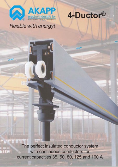
The perfect insulated conductor system<br />
with continuous conductors for<br />
current capacities 35, 50, 80, 125 and 160 A
AKAPP 4-<strong>Ductor</strong> ® current supply system<br />
Compact, reliable and safe current supply system for cranes, hoists, monorail systems, conveyor<br />
belts etc.<br />
The basic design of AKAPP 4-<strong>Ductor</strong> is a channel housing, in which four slots are prepared to<br />
accomodate copper conductors. The flat conductors are installed without the need for joints.<br />
Thanks to the design of the 4-<strong>Ductor</strong> and its continuous conductors, the system offers unique<br />
features as listed below.<br />
Which advantages does 4-<strong>Ductor</strong> ® offer you?<br />
• Excellent price/quality ratio. The concept of the<br />
continuous conductors and the use of only high quality<br />
components result in a trouble free feeding system against<br />
an agreeable price.<br />
• High mechanical strength. The PVC housing has a<br />
combination of high flexural yield, impact and tensile<br />
strength and is complemented by the design of associated<br />
components.<br />
• Continuous copper conductors. The flat copper<br />
conductors can be pulled from rolls into the previously<br />
installed PVC housing in long continuous lengths, without<br />
any connections in the conductor.<br />
• High current capacity. Copper conductors of various<br />
capacities can be pulled into the channels in the housing.<br />
Standard conductor capacaties are 35, 50, 80, 125 and<br />
160A.<br />
• Maximum power transmission. The brushes are<br />
positively located in the PVC housing and contact with the<br />
flat copper conductors is maintained by spring pressure.<br />
This guarantees a positive contact and excellent power<br />
transmission.<br />
• Exceptionally long carbon brush life is achieved due to<br />
the absence of conductor joints and connections which<br />
ensures trouble free operation.<br />
• Simple installation. Due to the light weight of the PVC<br />
housing, copper conductors without connections and the<br />
design of accessory components, system installation is a<br />
quick and easy operation.<br />
• Virtually maintenancefree. The PVC housing needs no<br />
maintenance and as previously mentioned continuous<br />
copper conductors ensure minimal brush wear. Thus<br />
minimising the presence of carbon deposits. Inspection<br />
periods can be scheduled in line with the schedule of the<br />
apparatus to be fed (i.e. a crane).<br />
• Safety to personnel.The high level of volume resistivity<br />
of the PVC housing ensures absolute safety to personnel.<br />
• No expansion problems. Due to the clearance that<br />
exists between the conductors and their location and the<br />
clearance between the PVC housing and sliding hangers,<br />
expansion due to changes in ambient temperature is<br />
accommodated without affecting the operation of the<br />
system. This also applies to extra long installations where<br />
standard components eliminate expansion problems often<br />
experienced with alternative systems.<br />
• Voltdrop absolute minimum and constant due to<br />
continuous copper conductors, thus avoiding problems<br />
associated with added resistance at joints and increased<br />
volt drop characteristics when joints loosen or corrode.<br />
• Compact design. By virtue of design, the 4-<strong>Ductor</strong><br />
system utilises an absolute minimum of space.<br />
For some applications, it is necessary to use the<br />
AKAPP Multiconductor® system (please refer to<br />
separate brochure). Typical examples are as follows:<br />
• 5 to 7 conductors are to be installed in one housing;<br />
• the system requires protection using flexible sealing<br />
strips;<br />
• the installation requires the use of transfer guides or<br />
isolation sections;<br />
Please note that, due to continuous innovations, technical<br />
specifications and performances listed in this catalogue, are<br />
subject to change without notice.<br />
• the travel speed is in excess of 60 m/min.;<br />
• a combination of the above.<br />
2
PVC housing<br />
Type RN4<br />
with 4 conductor slots to accommodate 4 copper<br />
conductors.<br />
Colour: grey (appr. RAL 7000)<br />
Temperature range -30ºC to +60ºC.<br />
The anti-reverse rib (A) in the housing ensures that the<br />
collector trolley can only be installed in one way and<br />
prevents cross phasing. A continuous yellow stripe (B) on<br />
one side of the housing ensures correct fitting of the<br />
system. The PVC with a high impact strength is selfextinguishing<br />
Technical data of the housings<br />
Material data<br />
Unplasticized Hard-PVC with approximate values:<br />
Notch shock strength<br />
5-10kJ/m²<br />
E-modulus<br />
2500-3000N/mm²<br />
Softening point (Vicat)<br />
81-83ºC<br />
Linear expansion 70.10 -6<br />
Electrical data<br />
Volume resistivity with l00V >4.10 15 Ω /cm<br />
Dielectric strength with 50 Hz<br />
>30 kV/mm<br />
Length of housing is standard 4 m; Special lengths are<br />
available.<br />
Copper conductors for housing RN4<br />
Each 4-<strong>Ductor</strong> installation is supplied with continuous flat<br />
copper conductors to suit the system length.<br />
Copper conductors type CU35, CU50, CU80, CU125 and<br />
CU160 for current capacities 35, 50, 80, 125 and 160A<br />
(duty cycle 80%) Material electrolitic copper.<br />
86,25 mm<br />
A<br />
51,4 mm<br />
B<br />
Maximum lengths of continuous conductor strip that<br />
can be pulled into the conductor housing: Cu35 and<br />
Cu50: 300m; Cu80: 250m; Cu125: 200m; Cu160: 150m<br />
Attachments for 4-<strong>Ductor</strong> housing<br />
Sliding hanger<br />
Type BN7-Z: galvanised;<br />
Type BN7-L: galvanised + epoxy coating.<br />
Center distance of hanger supports:<br />
2000 mm : possible for installations with conductors<br />
Cu35, Cu50 and Cu80;<br />
1333 mm : all installations.<br />
Fixed point clamp<br />
Type VMN7-Z: galvanised;<br />
Type VMN7-L: galvanised + epoxy coating.<br />
The system should be secured to the support construction<br />
adjacent to the electric feed point via a self clamping fixed<br />
point and then from this position free expansion is<br />
allowed to take place. When required, 2 provided self drilling<br />
screws can make the connection extra secure.<br />
Joint clamp<br />
Type VN7-Z: galvanised;<br />
Type VN7-L: galvanised + epoxy coating.<br />
The lengths of housing are connected by means of<br />
standard joint clamps. The clamps have special fixations<br />
whilst fitting the clamp halves. When required, 2 provided<br />
self drilling screws can make the connection extra secure.<br />
Insulating tape<br />
Type T50. 50 mm width, roll of 10 m. This adhesive tape<br />
is used to ensure a permanent shroud around the housing<br />
joints, prior to fitting the joint clamps.<br />
Support bracket, galvanised C-profile<br />
Type UH330, length 330 mm<br />
Type UH500, length 500 mm<br />
Type UH700, length 700 mm<br />
These brackets have clamps attached to sliding nut assemblies<br />
thus facilitating a flexible mounting arrangement capable<br />
of accomodating various sizes of RSJ (INP) beams,<br />
allowing simple horizontal adjustment.<br />
3<br />
UH<br />
BN7<br />
VN7<br />
T50<br />
VMN7
End feed boxes<br />
End feed box type AK7-28<br />
This box is supplied with connecting screws for<br />
connecting the supply cable cores (up to 4 cores) to the<br />
copper conductors. Feeding in via a cable gland Pg29 for<br />
cables ∅10-∅28 mm, e.g. 4 x 25 mm².<br />
End feed box type AN4-18<br />
A small end feed for connecting small cables up to<br />
∅18 mm. Length 200 mm.<br />
To attach this end feed box to the conductor housing a joint<br />
clamp is required (ordered separately).<br />
AK7-28<br />
AN4-18<br />
Line feed boxes<br />
Line feed box type LK28<br />
Feeding in via a cable gland Pg29 for cables<br />
∅10-∅28 mm, e.g. 4 x 25 mm².<br />
Line feed box type LK21-4<br />
Performance equal to LK28, however supplied with 4<br />
cable glands Pg21 for single core cables ∅10-∅21 mm<br />
(25 mm² and above). The feed connection comprises a<br />
transition box. AKAPP can inform you about the available<br />
types.<br />
Feed cables for line feed box LK21-4<br />
Single core cables, standard length 1,5 m. Provided with<br />
2 cable lugs (1 fitted at cable end and 1 separately)<br />
Type OK25 (1x25 mm²), ∅ 14,9 mm;<br />
Type OK35 (1x35 mm²), ∅ 15,3 mm;<br />
Type OK50 (1x50 mm²), ∅ 18,2 mm;<br />
Type OK70 (1x70 mm²), ∅ 20,8 mm.<br />
Line feed housings<br />
LK28<br />
LK21-4<br />
Connecting possibilities for feed cables when line feed is<br />
used.<br />
Line feed housing type LRNK4<br />
Length 1000 mm, supplied with 4 notches in which the<br />
feed clamps VK6, VK8 and VKN10 fit. The housing is<br />
mounted by means of 2 joint clamps in the 4-<strong>Ductor</strong> system<br />
and is secured to the support construction by 2 fixed<br />
point clamps.<br />
Feed clamp type VK6, with bolt M6, for copper<br />
conductors Cu35 and Cu50;<br />
Feed clamp type VK8, with bolt M8, for copper<br />
conductors Cu80, Cu125 and Cu160;<br />
Feed clamp type VKN10 (comprises an M10 screw<br />
attached to the connection plate with 2 pieces VK8 for<br />
cables up to 50 mm2), for copper conductors Cu125 and<br />
Cu160.<br />
Line feed box type LRN4<br />
2 pieces of housing 500 mm each, with 4 notches for<br />
protruding copper conductor ends<br />
The housing is mounted by means of 2 joint clamps in the<br />
4-<strong>Ductor</strong> system and is secured to the support<br />
construction by 2 fixed point clamps.<br />
LRNK4<br />
VKN10<br />
LRN4<br />
End cap type EN4<br />
Length 200 mm. For closing off the open ends of<br />
a 4-<strong>Ductor</strong> system. Fitted to the housing by<br />
means of a joint clamp (ordered separately).<br />
EN4<br />
4
Collector trolleys<br />
The current is fed from the Multiconductor to static or<br />
mobile equipment via the collector trolley. The actual<br />
connection to the flat conductors is via spring loaded<br />
carbon brushes which are manufactured from a special<br />
bronze/carbon alloy having a high wear factor.<br />
The collector trolley is pulled along the 4-<strong>Ductor</strong><br />
installation by the apparatus/machine being fed, on which<br />
the towing arm is mounted.<br />
The standard collector trolleys are suitable for traversespeeds<br />
up to 60 m/min.<br />
Standard collector trolleys<br />
Collector trolleys are available for 4 conductors with<br />
current carrying capacities of 35, 70 and 100A; duty cycle<br />
60%. The 70A trolleys and 100A trolleys are formed by<br />
mounting 2 resp. 3 separate trolleys 35A on a metal strip<br />
(see the figures opposite). Existing trolleys can be easily<br />
transformed.<br />
All collector trolleys can be delivered with or without 1 m<br />
tail (type "C4-..", resp. "CL4-..").<br />
It is recommended to use a transition box when<br />
connecting the trolley with the apparatus to be fed (see<br />
figures below). This box (order separately) can be<br />
mounted close by on the apparatus or machine.<br />
C4-35<br />
CL4-70<br />
strip for C(L)4-70<br />
CL4-100<br />
CL4-35<br />
Transition boxes for collector trolleys<br />
This unit facilitates the connection of the flexible cable<br />
from the collector trolley with the fixed wiring from the<br />
apparatus/machine being fed. Using the included<br />
attachments, the transition box can be mounted easily on<br />
the (AKAPP) towing arm or close by on the apparatus/<br />
machine.<br />
Types of transition boxes:<br />
type for trolley inlet outlet<br />
OG35-7 C(L)4-35 1xPg21 1xPg21<br />
OG70-5 C(L)4-70 2xPg21 1xPg29<br />
OG100-5 C(L)4-100 3xPg21 1xPg36<br />
strip for C(L)4-100<br />
OG70-5<br />
cable gland permits<br />
cable out to<br />
apparatus to be fed<br />
cable glands permit<br />
trolley cables in<br />
Trolley towing arm<br />
Types BMV35, BMV70 and BMV100, for<br />
collector trolleys resp. 35A, 70A and 100A.<br />
A towing arm is attached to the moving machinery and<br />
connected to the collector trolley via chains. The arrangement<br />
is such that when pulling in either direction one of<br />
the collector towing chains is taut, the other remaining<br />
slack. In this way lateral movements of the crane, hoist,<br />
etc. are not transmitted to the trolley. This tolerance provides<br />
ultimate security of service!<br />
BMV35 +<br />
OG35-7<br />
BMV70 +<br />
OG70-5<br />
Attention: The towing connector on the arm should be<br />
installed 10 mm lower than the towing connection on the<br />
trolley in the highest position and at 30 mm lower than the<br />
towing connection on the trolley in the lowest position and<br />
should be aligned directly below the housing opening in<br />
the vertical plane.<br />
BMV100 +<br />
OG100-5<br />
5
4-<strong>Ductor</strong> system configuration<br />
A. Installation with end feed box (AK)<br />
2300<br />
2000<br />
2000<br />
2000 2000<br />
n x 2000<br />
1633 1333 1333 1333<br />
1333 1333 1333<br />
1333 1333 n x 1333<br />
AK<br />
VMN7<br />
VN7<br />
BN7<br />
300<br />
4000<br />
300 300<br />
4000<br />
4000<br />
B. Installation with line feed box (LK)<br />
n x 2000<br />
2000<br />
2000<br />
1900<br />
1900<br />
n x 2000<br />
n x 1333 1333 1333 1333 1233<br />
1233 1333 n x 1333<br />
BN7<br />
VN7<br />
VMN7<br />
LK<br />
300<br />
4000<br />
300<br />
500<br />
300<br />
500<br />
Note:<br />
In the examples above there are two possibilities shown for the centre distance of the support hangers. We recommend:<br />
1333 mm: all installations<br />
2000 mm: only possible when copper conductors max. 80A are used<br />
AKAPP offers you more!<br />
AKAPP products are used all over the world in<br />
many various applications and circumstances.<br />
AKAPP is represented<br />
worldwide in over 40 countries.<br />
Our wide product range offers solutions<br />
for numerous problems concerning mobile power<br />
feed systems. No wonder that AKAPP has a<br />
leading position!<br />
AKAPP has a long term experience and therefore<br />
our staff offer you fast and expert advise; free<br />
of charge!<br />
For free copies of catalogues as listed opposite,<br />
or product information, please contact your<br />
AKAPP supplier.<br />
• Multiconductor (multipole insulated current rail)<br />
• Monoconductor (monopole insulated current rail)<br />
• Pro-<strong>Ductor</strong> (multipole insulated flat current rail)<br />
• T-bar systems<br />
• Self winding cable and hose reels<br />
• Spring driven cable and hose reels<br />
• Motor driven cable and hose reels<br />
• Portable hand winded reels<br />
• Slip rings<br />
• Festoon systems<br />
• Plastic and steel energy chains<br />
• Special cables<br />
• Grounding reels<br />
• Balancers<br />
AKAPP offices:<br />
The Netherlands (head office)<br />
Nijverheidsweg 14<br />
3771 ME Barneveld<br />
Tel. (+31) 342-403900<br />
Fax (+31) 342-403912<br />
e-mail : info@akapp.com<br />
Internet : www.akapp.com<br />
Germany<br />
Hohenzollernstr. 11-13<br />
40211 Düsseldorf<br />
Tel. (+49) 211-4987261<br />
Fax (+49) 211-4987231<br />
Belgium<br />
Battelsesteenweg 455A<br />
2800 Mechelen<br />
Tel. (+32) 15-281718<br />
Fax (+32) 15-281701<br />
6