insul 8
insul 8
insul 8

Create successful ePaper yourself
Turn your PDF publications into a flip-book with our unique Google optimized e-Paper software.
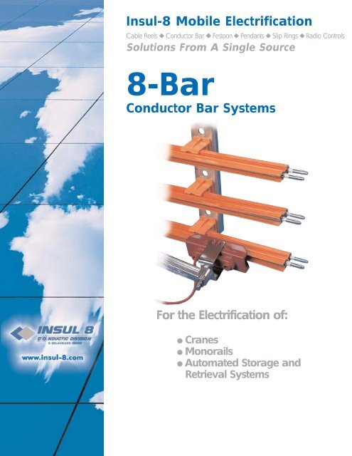
Insul-8 Mobile Electrification<br />
Cable Reels ◆ Conductor Bar ◆ Festoon ◆ Pendants ◆ Slip Rings ◆ Radio Controls<br />
Solutions From A Single Source<br />
8-Bar<br />
Conductor Bar Systems<br />
For the Electrification of:<br />
● Cranes<br />
● Monorails<br />
● Automated Storage and<br />
Retrieval Systems
INSUL-8 CORPORATION<br />
THE INDUSTRY STANDARD FOR OVER 50 YEARS<br />
• Product Design<br />
• Commitment to Quality<br />
• Customer Service<br />
• Quick and Reliable Deliveries<br />
• Low Maintenance Systems<br />
• Engineering Assistance<br />
Insul-8 figure 8-Bar has been the industry's standard for over 50 years. It remains a highly<br />
economical and reliable solution to your mobile electrification needs for cranes and monorails<br />
as well as trolleys, hoists, conveyors and many other applications. Insul-8 specializes<br />
in engineered systems, covering a wide variety of both standard and custom designs.<br />
FIGURE 8-BAR IS AVAILABLE IN:<br />
• 40 Amp.<br />
• 90 Amp.<br />
• 110 Amp.<br />
• 250 Amp.<br />
• 250 Amp.<br />
• 350 Amp.<br />
• 500 Amp.<br />
Stainless Steel<br />
Galvanized Steel<br />
Galvanized Steel<br />
Copper Steel Laminate<br />
Stainless Clad Copper Laminate<br />
Rolled Copper<br />
Solid Copper<br />
INCLUDES THESE OUTSTANDING FEATURES:<br />
• UL listed and CSA Approved<br />
• Low maintenance<br />
• Fast, simple installation<br />
• Insul-8 Bar is the original figure 8-Bar<br />
• 50 years of experience in the industry<br />
CALL NOW! FOR ALL YOUR MOBILE ELECTRIFICATION NEEDS.<br />
800/521-4888(USA)<br />
800/677-2487(CANADA)<br />
402/339-9300<br />
INSUL-8-BAR<br />
2
TABLE OF CONTENTS<br />
8-Bar Components and Definitions ..............4<br />
Selecting a System .......... ............................5<br />
Quick Pick Selection ....................................6<br />
8-Bar Components........................................8<br />
Hangers and Anchor Clamps ....................13<br />
Collectors....................................................14<br />
Brackets ....................................................16<br />
Universal Brackets......................................17<br />
Preassembled Bracket Order Form ............18<br />
Slip Rings and Curves ................................19<br />
Curve Definition Sheet ................................20<br />
Engineering Data........................................21<br />
Specifications May Change Without Notice.<br />
INSUL-8-BAR<br />
3
BASIC 8-BAR COMPONENTS<br />
End<br />
Cover<br />
Power Feed<br />
Hanger<br />
Clamp<br />
8-Bar<br />
Conductor<br />
1" Square<br />
Bar<br />
Collector<br />
1) Conductor Bar<br />
The supply of incoming power.<br />
2) Powerfeed<br />
Attachment of incoming power.<br />
3) Collector<br />
Collects the incoming power and forwards to machine.<br />
4) Hangers<br />
Supports the conductor bar.<br />
5) End Cover<br />
Safety protection at the end of conductor system.<br />
6) Brackets<br />
Supporting device for attachment of multiple hangers.<br />
7) Anchor Clamp<br />
Supporting device for directing movement of conductors during thermal expansion and contraction.<br />
INSUL-8-BAR<br />
4
SYSTEM SELECTION<br />
SELECTING A SYSTEM IS SIMPLE<br />
To assist you in selecting an 8-Bar system, answer the following questions.<br />
Return via fax and we’ll provide a quote and qualified customer support .<br />
1) Type of system (Runway, Bridge, Monorail, Other)__________________<br />
2) Length of System (ft.)_____ 3) Number of Conductors______<br />
4) Number of vehicles (cranes, etc.)____<br />
5) Voltage________ AC___ DC___ Phase____ Cycle____<br />
6) Amperage requirement of each vehicle_______(see pg. 21)<br />
7) Total ampacity required_______(see pg. 21)<br />
8) Environment: Indoor___ Outdoor ___ Both____<br />
9) Ambient temperature: (if other than -10° F to +100° F)____ to ____<br />
10) Atmosphere: Dry___ Wet___ Dusty ___ Dirty___<br />
Corrosive___ Nuclear___ Other_____________<br />
11) Bracket Required: No____ Web 5"____ Web 9"___ Flange___<br />
12) Do you want brackets supplied: Yes____ No____<br />
13) Special Concerns:_______________________________________<br />
Curved systems? Please refer to pgs. 19 and 20 for proper selection.<br />
Icing problem? We offer heated systems. Consult factory for details.<br />
NEED ASSISTANCE?<br />
CONTACT INSUL-8 OR YOUR LOCAL REPRESENTATIVE NOW!<br />
WE'LL BE HAPPY TO QUOTE YOUR SYSTEM<br />
OR PARTS REQUIREMENTS FOR YOU.<br />
INSUL-8-BAR<br />
5
QUICK PICK<br />
PICK YOUR SYSTEM<br />
The following components make up standard conductor bar systems used on cranes, monorails, conveyors and<br />
other mobile electrification applications.<br />
1) Conductor bar amperage required?<br />
2) Hanger Clamps to support the bar (Indoor or Outdoor)? (See pg.13)<br />
3) Brackets required? ( pgs. 16 and 17)<br />
4) Powerfeeds: attachment to incoming power.<br />
5) End covers: for protection at the end of system.<br />
6) Collectors: to conduct the power from the electrified bar to the motors that are used to power the crane,<br />
hoist, etc.<br />
Notes: Connector tool is included free with the complete system.<br />
Connector Pins, Joint Covers, and where applicable Joint Keepers supplied at no additional charge<br />
with each conductor bar.<br />
Expansion sections may be required to compensate for thermal expansion.<br />
Consult factory for stainless steel hardware requirements.<br />
STAINLESS STEEL 40 AMP.<br />
40 AMP Description W/Rigid PVC Cover W/Medium Heat Cover W/High Heat Cover<br />
-10 0 F. to 160 0 F. -25 0 F. to 250 0 F. -60 0 F. to 400 0 F.<br />
Part Length Part # Approx. WT(lbs.) Part # Approx. WT(lbs.) Part # Approx. WT(lbs.)<br />
Conductor Length 10' 14299 7.0 24304 6.6 24307 7.5<br />
Conductor Length 5' 14823 3.5 24305 3.3 24308 3.8<br />
Expansion Section 10' 24279 11.0 24306 7.0 24309 11.8<br />
with<br />
connector pins<br />
Powerfeed 11091 .34 11091 .34 11122 .34<br />
End Cover 11088 .10 11088 .10 11633 .10<br />
GALVANIZED STEEL 90 AMP. AND 110 AMP.<br />
90 AMP Description W/Rigid PVC Cover W/Medium Heat Cover W/High Heat Cover<br />
-10 0 F. to 160 0 F. -25 0 F. to 250 0 F. -60 0 F. to 400 0 F.<br />
Part Length Part # Approx. WT(lbs.) Part # Approx. WT(lbs.) Part # Approx. WT(lbs.)<br />
Conductor Length 10' 22135 4.4 22141 4.1 22147 4.9<br />
Conductor Length 5' 22136 3.5 22142 2.1 24148 2.5<br />
Expansion Section 10' 22140 6.7 22146 6.3 22152 7.4<br />
Powerfeed 11091 .34 11091 .34 11122 .4<br />
with<br />
connector pins End Cover 22070 .03 22070 .10 11633 .4<br />
110 AMP Description W/Rigid PVC Cover W/Medium Heat Cover W/High Heat Cover<br />
-10 0 F. to 160 0 F. -25 0 F. to 250 0 F. -60 0 F. to 400 0 F.<br />
Part Length Part # Approx. WT(lbs.) Part # Approx. WT(lbs.) Part # Approx. WT(lbs.)<br />
Conductor Length 10' 11000 5.5 11019 5.8 11038 6.7<br />
Conductor Length 5' 11001 2.8 11020 2.9 11039 3.4<br />
Expansion Section 10' 11057 9.5 11064 8.9 11070 10.3<br />
Powerfeed 11091 .34 11091 .34 11122 .4<br />
with<br />
connector pins End Cover 11088 .10 11088 .10 11633 .4<br />
INSUL-8-BAR<br />
6<br />
DON’T SEE WHAT YOU NEED? CALL US!
QUICK PICK<br />
250 AMP Description W/Rigid PVC Cover W/Medium Heat Cover W/High Heat Cover<br />
-10 0 F. to 160 0 F. -25 0 F. to 250 0 F. -60 0 F. to 400 0 F.<br />
Part Length Part # Approx. WT(lbs.) Part # Approx. WT(lbs.) Part # Approx. WT(lbs.)<br />
Conductor Length 10' 11004 6.6 11023 6.2 11042 7.1<br />
Conductor Length 5' 11005 3.3 11024 3.1 11043 3.6<br />
Expansion Section 10' 11059 8.5 11065 8.0 11071 9.2<br />
with<br />
connector pins<br />
STAINLESS CLAD COPPER 250 AMP.<br />
Powerfeed 11092 .7 11092 .7 11093 .7<br />
End Cover 11088 .10 11088 .10 11633 .4<br />
COPPER STEEL LAMINATE 250 AMP.<br />
250 AMP Description W/Rigid PVC Cover W/Medium Heat Cover W/High Heat Cover<br />
-10 0 F. to 160 0 F. -25 0 F. to 250 0 F. -60 0 F. to 400 0 F.<br />
Part Length Part # Approx. WT(lbs.) Part # Approx. WT(lbs.) Part # Approx. WT(lbs.)<br />
Conductor Length 10' 11008 6.2 11027 5.8 11046 6.7<br />
Conductor Length 5' 11009 3.1 11028 2.9 11047 3.4<br />
Expansion Section 10' 11060 10.0 11066 9.4 11072 10.8<br />
Powerfeed 11092 .7 11092 .7 11093 .70<br />
with<br />
connector pins End Cover 11088 .10 11088 .10 11633 .4<br />
ROLLED COPPER 350 AMP.<br />
350 AMP Description W/Rigid PVC Cover W/Medium Heat Cover W/High Heat Cover<br />
-10 0 F. to 160 0 F. -25 0 F. to 250 0 F. -60 0 F. to 400 0 F.<br />
Part Length Part # Approx. WT(lbs.) Part # Approx. WT(lbs.) Part # Approx. WT(lbs.)<br />
Conductor Length 10' 11012 7.0 11031 6.6 11050 7.5<br />
Conductor Length 5' 11013 3.5 11032 3.3 11051 3.8<br />
Expansion Section 10' 11062 11.0 11068 11.0 11074 11.8<br />
Powerfeed 11092 .7 11092 .7 11093 .70<br />
with<br />
connector pins End Cover 11088 .10 11088 .10 11633 .4<br />
SOLID COPPER 500 AMP.<br />
500 AMP Description W/Rigid PVC Cover W/Medium Heat Cover W/High Heat Cover<br />
-10 0 F. to 160 0 F. -25 0 F. to 250 0 F. -60 0 F. to 400 0 F.<br />
Part Length Part # Approx. WT(lbs.) Part # Approx. WT(lbs.) Part # Approx. WT(lbs.)<br />
Conductor Length 20' 11016 23.6 11035 22.1 11054 24.6<br />
Conductor Length 10' 11017 11.8 11036 11.0 11055 12.3<br />
Expansion Section 10' 11063 18.5 11069 17.3 11075 20.0<br />
with copper connector<br />
clamp and case<br />
Powerfeed 11094 2.6 11094 .66 11094 2.6<br />
End Cover 12171 .2 11633 .2 11633 .4<br />
WE SPECIALIZE IN SPECIAL APPLICATIONS.<br />
INSUL-8-BAR<br />
7
8-BAR COMPONENTS<br />
8-BAR<br />
Rigid, figure 8-Bar is furnished in standard lengths, with connectors, joint cover and <strong>insul</strong>ating cover.<br />
(Copper Bar Also Includes Joint Keepers.)<br />
(90 Amp Bar Shown)<br />
For proper 8-Bar selection<br />
see Quick Pick Section (pg 6-7)<br />
8-BAR COVER<br />
Meets all requirements for plastic electrical <strong>insul</strong>ation, and may be used indoors or outdoors.<br />
Part # Material Temp. Replacement Approx.<br />
Rating Length Weight<br />
11114 Rigid PVC -10° F to 9'-10 1/2" 1.2<br />
(Orange) +160° F<br />
11115 Medium Heat -25° F to 9'-10 1/2" 0.9<br />
(Lexan)(Red) +250° F<br />
11116 High Heat -60° F to 9'-7 1/4" 1.7<br />
(Polyester) +400° F<br />
CONNECTOR PINS<br />
Used to connect two bar sections together<br />
for quick and easy installation.<br />
(#21914)<br />
(#11120)<br />
Part #<br />
Description<br />
11120 Steel zinc plated used with<br />
galvanized steel 110 amp 8-Bar<br />
11121 Used with rolled copper<br />
and laminated 8-Bar<br />
24196 Stainless steel used with<br />
stainless steel 40 amp 8-Bar<br />
21914 Steel zinc plated used with<br />
galvanized steel 90 amp 8-Bar<br />
22885 Transition Pin for 90 and 110 amp<br />
8-Bar, 3" long<br />
JOINT COVER<br />
Insulated protective covers<br />
for conductor bar jointing parts.<br />
Part # Description Approx.<br />
Weight<br />
13601 For 40 - 350 amp PVC cover .03<br />
13600 For 40 - 350 amp Medium Heat Cover .03<br />
11123 For 40 - 350 amp High Heat Cover .40<br />
INSUL-8-BAR<br />
8
8-BAR COMPONENTS<br />
COPPER CONNECTOR CLAMP AND CASE<br />
Part # Description Approx.<br />
Weight<br />
Used to connect 500 Amp.<br />
solid copper conductor together.<br />
Complete assembly for<br />
11117 solid copper 8-Bar, or for repairs 1.5<br />
11118 Connector Case Only 0.5<br />
11119 Connector Clamp Only 1.0<br />
✱ Used with all cover types<br />
(#11117)<br />
JOINT KEEPER<br />
Part # Description Approx.<br />
Weight<br />
Used to help secure copper conductor<br />
bar together and add stability.<br />
11125 For rolled copper and laminated 8-Bar .01<br />
JOINT REPAIR KIT<br />
Part # Description Approx.<br />
Weight<br />
To repair joints of damaged conductor bar.<br />
24632 For 40 - 350 amp. formed 8-Bar .66<br />
✱ For use with PVC cover only<br />
Part # Description Approx.<br />
Weight<br />
11134 Used with 40 - 350 amp. 8-Bar 2.3<br />
CONNECTOR TOOL<br />
Insert into the pre-punched holes<br />
of the conductor bar, pull together until<br />
conductor sections butt together securely.<br />
INSUL-8-BAR<br />
9
8-BAR COMPONENTS<br />
END COVER<br />
For covering the end of exposed figure 8-Bar.<br />
Part # Description Approx.<br />
Weight<br />
11088 For 40, 110-350 amp. conductors to 300° F. .03<br />
22070 For 90 amp. conductors to 400° F. .03<br />
11633 For all 8-shaped conductors to 400° F. .40<br />
12171 For 500 amp. (solid copper) conductors .40<br />
to 160° F.<br />
(#11088)<br />
27102 For 500 amp. (solid copper) to 160° F .40<br />
(stainless steel hardware)<br />
POWERFEED AND ACCESSORIES<br />
Fully <strong>insul</strong>ated, simple clamp<br />
design for easy installation anywhere<br />
on the system. It provides attachment of<br />
incoming power to the conductor rails.<br />
Part # Description Approx.<br />
Weight<br />
11091 90/110 amp. steel clamp and<br />
PVC case 160° F. .34<br />
11122 90/110 amp steel clamps and<br />
high heat case, 400° F. .38<br />
11092 250 amp. copper clamp and<br />
PVC case, 160° F. .66<br />
11093 250 amp. copper clamp and<br />
high heat case, 400° F. .70<br />
11094 500 amp. copper clamp with<br />
high heat case, 400° F. 2.60<br />
27104 250 amp. copper clamp and<br />
PVC case, 160° F (stainless hardware) .66<br />
27106 500 amp. copper clamp with<br />
high heat case 400° F. (Stainless Hardware) 2.60<br />
(#11091)<br />
Part # Description Approx.<br />
Weight<br />
11131 Case Clip Only. PVC 90/110, 250 amp .2<br />
11132 Case Clip Only. High Heat. .3<br />
90/110, 250 amp<br />
11133 Case Clip Only. High Heat 500 amp 1.0<br />
11128 Clamp Only. Steel 90/110 amp .10<br />
11129 Clamp Only. Copper, 250 amp .4<br />
11130 Clamp Only. Copper, 500 amp 1.6<br />
INSUL-8-BAR<br />
10
8-BAR COMPONENTS<br />
EXPANSION SECTION<br />
Used every 300' for steel conductors, every 200' for copper conductors to compensate for thermal expansion.<br />
Powerfeeds and flexible jumpers are factory installed to meet electrical and mechanical<br />
requirements of your system.<br />
For proper expansion section selection<br />
see quick pick (pgs. 6-7)<br />
✱ To determine system expansion<br />
requirements see page 26.<br />
ISOLATION SECTION<br />
Conductor isolation sections are available for sectionalizing control circuits, maintenance bays, etc.<br />
Consult factory for proper selection.<br />
ISOLATION SECTION PARTS<br />
Components used for in-field modification.<br />
Part # Description Approx.<br />
Weight<br />
Kit: with 11127 guide assembly. 2.3<br />
21841 PVC cover and isolation piece<br />
For 40 - 350 amp. Except 90 amp.<br />
11427 Molded plastic. 0.3<br />
Insulating piece only for 21841<br />
(#11427)<br />
Modeled plastic, 1" isolating pin.<br />
11615 For 40-350 amp, except for 90 amp. 0.03<br />
(2 per location required)<br />
Modeled plastic, 1" isolating pin.<br />
11618 For 90 amp only. .03<br />
(2 per location required)<br />
(#11618)<br />
INSUL-8-BAR<br />
11
8-BAR COMPONENTS<br />
TRANSFER CAPS<br />
Used in switches, interlocks to<br />
accomplish smooth collector transfer.<br />
Part # Description Approx.<br />
Weight<br />
22070 End/transfer cap for 90 amp bar. 0.03<br />
22395 Left transfer cap 90 amp bar 0.03<br />
22396 Right transfer cap for 90 amp bar 0.03<br />
13161 End/transfer cap for 0.03<br />
40-350 amp bar<br />
14118 Left hand cap for 0.03<br />
40-350 amp bar<br />
(#22070)<br />
14119 Right hand cap for 0.03<br />
40-350 amp bar<br />
GUIDE ASSEMBLY<br />
To provide rigid support at isolation areas.<br />
Part # Description Approx.<br />
Weight<br />
11127 Galvanized steel 1.5<br />
PICK-UP GUIDE<br />
Requires use of self-centering collectors to allow the<br />
collector to leave the conductor and be re-tracked<br />
on return. Consult factory for selection.<br />
Part # Description Approx.<br />
Weight<br />
13142 For "J" head collectors, indoors, 1.75<br />
for 3" bar spacing<br />
11089 For "J" head collectors, indoors, 1.75<br />
for 4" bar spacing<br />
(#13142)<br />
13143 For "J" head collectors, outdoors, 2<br />
for 3" bar spacing<br />
11090 For "J" head collectors, outdoors, 2<br />
for 4" bar spacing<br />
(#13143)<br />
INSUL-8-BAR<br />
12
HANGER AND ANCHOR CLAMPS<br />
Hanger Clamps<br />
Hanger clamps are designed to grip<br />
the figure 8-Bar shape for stable support.<br />
RECOMMENDED HANGER SPACING<br />
Locate every 5 feet for vertical entry.<br />
Locate every 3 feet for curved systems.<br />
Locate every 3 feet 4 inches for lateral entry.<br />
Insulated Hangers Recommended for Outdoor Applications<br />
PLASTIC SNAP-IN HANGER CLAMP<br />
For standard mount, not recommended for curves or lateral mount.<br />
with <strong>insul</strong>ator<br />
Description Part # Approx.<br />
Weight<br />
Polycarbonate plastic 24405 .3<br />
with plated hardware<br />
Polycarbonate plastic<br />
with stainless steel 28122 .3<br />
hardware<br />
Description Part # Approx.<br />
Weight<br />
Polycarbonate plastic 22800 0.11<br />
with plated hardware<br />
Polycarbonate plastic<br />
with stainless steel 23370 0.11<br />
hardware<br />
STEEL SNAP-IN HANGER CLAMP<br />
For standard mount, not recommended for curves or lateral mount.<br />
Description Part # Approx.<br />
Weight<br />
Spring Steel 22000 0.23<br />
Description Part # Approx.<br />
Weight<br />
Spring Steel 21600 0.11<br />
with <strong>insul</strong>ator<br />
CROSS-BOLT HANGER CLAMP<br />
For use on standard mount, lateral mount, and curved systems<br />
with <strong>insul</strong>ator<br />
Description Part # Approx.<br />
Weight<br />
Plated Steel 11082 0.4<br />
Stainless Steel 11084 0.4<br />
Description Part # Approx.<br />
Weight<br />
Plated Steel 11076 0.25<br />
Stainless Steel 11078 0.3<br />
ANCHOR CLAMPS<br />
For use at mid-point or between expansion sections and ends.<br />
with <strong>insul</strong>ator<br />
Description Part # Approx.<br />
Weight<br />
Plated Steel 21982 0.5<br />
Stainless Steel 28124 0.5<br />
Description Part # Approx.<br />
Weight<br />
Plated Steel 21833 0.3<br />
Stainless Steel 28123 0.3<br />
INSUL-8-BAR<br />
13
COLLECTORS<br />
Collector assemblies are offered in either single or double contact shoe type providing a current take-off from<br />
30 to 200 amperes. The collectors are the sliding contact type which confines wear to the easily replaceable<br />
contact shoe. The contact shoes are supported by <strong>insul</strong>ated shoe holders on spring loaded collector arms<br />
designed to articulate and swivel.<br />
Example of standard mount,<br />
vertical entry<br />
30 AMP COLLECTORS<br />
"J" Head "C" Base Type<br />
For straight runs and curves<br />
to 18" minimum radius.<br />
For lateral mount, consult factory.<br />
Part # Description Approx.<br />
Weight<br />
13128 Standard mount 2.5<br />
13130 Standard mount, self centering ✱ 2.6<br />
"J" Head "H" Base Type<br />
For straight runs and curves<br />
to 18" minimum radius.<br />
For lateral mount, consult factory.<br />
Part # Description Approx.<br />
Weight<br />
13131 Standard mount 1.4<br />
13132 Standard mount, self centering ✱ 1.7<br />
13082 Standard tandem mount 4.7<br />
13084 Standard tandem mount, self-centering ✱ 4.9<br />
100 AMP COLLECTORS<br />
"J" Head "C" Base Type<br />
For straight runs and discontinuous<br />
systems of 600V, or less. For lateral mount,<br />
consult factory.<br />
Part # Description Approx.<br />
Weight<br />
13613 Standard mount 3.1<br />
13625 Standard mount, self centering ✱ 3.2<br />
"J" Head "H" Base Type<br />
For straight runs and discontinuous<br />
systems of 600V, or less and curves to minimum of<br />
48" radius. For lateral mount, consult factory.<br />
Part # Description Approx.<br />
Weight<br />
13629 Standard mount 2.2<br />
13630 Standard mount, self centering ✱ 2.2<br />
13626 Standard tandem mount 5.8<br />
13628 Standard tandem mount, self-centering ✱ 6.0<br />
✱ For use with Pick-up Guides only.<br />
INSUL-8-BAR<br />
14
COLLECTORS<br />
"C" BASE COLLECTORS<br />
(#13626)<br />
(#13128) (#13130)<br />
"H" BASE COLLECTORS<br />
(#13630)<br />
(#13131)<br />
INSUL-8-BAR<br />
15
BRACKETS<br />
BRACKETS ONLY<br />
Zinc plated steel brackets (See page 13 for hangers).<br />
Web Mount<br />
Main line/top running applications,<br />
web mounted bottom entry systems.<br />
Flange Mount<br />
Monorail/underhung applications,<br />
flange mounted bottom entry systems.<br />
(#22014)<br />
Note: 9" bracket has position for 4th hanger at 6"<br />
Part # Description Approx. Weight<br />
21784 Web bracket 5" 1.25<br />
Part # Description Approx. Weight<br />
22095 Flange bracket 1.77<br />
22014 Web bracket 9" 2.35<br />
BRACKETS WITH HANGER CLAMPS<br />
The above brackets are pre-assembled with hanger clamps on 3" centers.<br />
(#22019) (#23380)<br />
Without Insulators<br />
Steel Snap-In Clamps<br />
With Insulator<br />
Plastic<br />
Snap-In Clamps<br />
Description Part # Approx. Weight Part # Approx. Weight Part # Approx. Weight<br />
Web type 5" 22017 1.55 22011 1.95 23378 1.55<br />
Web type 9" 22019 2.68 22021 3.10 23379 2.68<br />
Flange 22079 2.1 22080 2.5 23380 2.1<br />
Cross Bolt Clamps<br />
Without Insulator<br />
With Insulator<br />
Description Part # Approx. Weight Part # Approx. Weight<br />
Web type 5" 22096 1.97 22099 2.33<br />
Web type 9" 22103 3.10 22106 3.50<br />
Flange 22110 2.52 22113 2.88<br />
INSUL-8-BAR<br />
16
UNIVERSAL BRACKETS<br />
1” ON CENTER PREDRILLED HOLES. LARGER NUMBER OF POSITIONS<br />
ALLOWS "UNIVERSAL BRACKETS" TO ADDRESS MOST APPLICATIONS<br />
WEB BRACKET - SHORT<br />
WEB BRACKET - LONG<br />
Part #<br />
Approx. Wt.<br />
Part #<br />
Approx. Wt.<br />
31409 1.0<br />
31407 1.25<br />
FLANGE BRACKET<br />
FLANGE BRACKET WITH CLIPS<br />
Part #<br />
Approx. Wt.<br />
Part #<br />
Approx. Wt.<br />
31408 1.15<br />
31418 1.55<br />
ORDER PREASSEMBLED BRACKETS<br />
WITH YOUR CHOICE OF HANGERS PG. 18<br />
INSUL-8-BAR<br />
17
PREASSEMBLED BRACKET ORDER FORM<br />
DIRECTIONS<br />
1) Make BRACKET selection and identify (in parantheses) the hole number<br />
locations in which hangers are to be assembled. (see bottom of page for<br />
recommended minimum hanger spacing).<br />
2) Make hanger selection (see pg. 13).<br />
EXAMPLE:<br />
Qty. Part # Description<br />
10 31407 (1,3,5,7) Long Bracket<br />
40 22800 Plastic Snap Hange<br />
BRACKET HOLE LISTING (1" SPACING BETWEEN)<br />
RECOMMENDED MINIMUM CONDUCTOR BAR SPACING<br />
Indoor Outdoor<br />
Insul-8-Bar 2" 3"<br />
Side Contact 3" Not for outside use<br />
(Lateral Mount)<br />
For less than 2" spacing, consult factory.<br />
INSUL-8-BAR<br />
18
SLIP RINGS AND CURVES<br />
Conductor Bar Cover Minimum Maximum Part #<br />
Radius Length<br />
Galvanized Steel PVC 18" 10' 11003<br />
(110 amp)<br />
Stainless Clad PVC 18" 10' 11007<br />
Copper Laminate<br />
(250 amp)<br />
Copper Steel PVC 18" 10' 11011<br />
Laminate<br />
(250 amp)<br />
Rolled Copper PVC 18" 10' 11015<br />
(350 amp)<br />
Solid Copper PVC 18" 10' 11018<br />
(500 amp)<br />
Galvanized Steel Med. 57" 10' 11022<br />
(110 amp) Heat<br />
Stainless Clad Med. 57" 10' 11026<br />
Copper Laminate Heat<br />
(250 amp)<br />
Copper Steel Med. 57" 10' 11030<br />
Laminate Heat<br />
(250 amp)<br />
Rolled Copper Med. 57" 10' 11034<br />
(350 amp) Heat<br />
Solid Copper Med. 57" 10' 11037<br />
(500 amp) Heat<br />
Galvanized Steel High 57" 10' 11041<br />
(110 amp) Heat<br />
Stainless Clad High 57" 10' 11045<br />
Copper Laminate Heat<br />
(250 amp)<br />
Copper Steel High 57" 10' 11049<br />
Laminate Heat<br />
(250 amp)<br />
Rolled Copper High 57" 10' 11053<br />
(350 amp) Heat<br />
Solid Copper High 57" 10' 11056<br />
(500 amp) Heat<br />
CONSULT FACTORY FOR<br />
CURVES<br />
Factory curved conductors. Refer to<br />
page 20 to specify your curve requirements.<br />
ASSISTANCE WITH YOUR<br />
CURVE AND SLIP RING REQUIREMENTS.<br />
SLIP RINGS<br />
Curved segments for factory<br />
manufactured ring.<br />
Conductor Bar Ring Part #<br />
Description<br />
Galvanized Steel 23626<br />
(110 amp)<br />
Stainless Clad 18" to 35"<br />
Copper Laminate radius 2-180° 23627<br />
(250 amp) pieces<br />
Copper Steel<br />
Laminate PVC Cover 23628<br />
(250 amp)<br />
Rolled Copper 23629<br />
(350 amp)<br />
Galvanized Steel 23630<br />
(110 amp)<br />
Stainless Clad 35.1" to 54"<br />
Copper Laminate radius 23631<br />
(250 amp) 3-120° pieces<br />
Copper Steel<br />
Laminate PVC Cover 23632<br />
(250 amp)<br />
Rolled Copper 23633<br />
(350 amp)<br />
Solid Copper 24292<br />
(500 amp)<br />
Galvanized Steel 23634<br />
(110 amp)<br />
Stainless Clad 54.1" to 72"<br />
Copper Laminate radius 23635<br />
(250 amp) 4-90° pieces<br />
Copper Steel PVC Cover 23636<br />
Laminate<br />
(250 amp)<br />
Rolled Copper 23637<br />
(350 amp)<br />
Solid Copper 24293<br />
(500 amp)<br />
Galvanized Steel 23638<br />
(110 amp)<br />
Stainless Clad 57" to 72"<br />
Copper Laminate radius 23639<br />
(250 amp) 4-90° pieces<br />
Copper Steel Medium Heat 23640<br />
Laminate<br />
(250 amp)<br />
Rolled Copper<br />
Cover<br />
23641<br />
(350 amp)<br />
Solid Copper 24294<br />
(500 amp)<br />
INSUL-8-BAR<br />
19
CURVE DEFINITION SHEET<br />
Consult factory when calculating your requirements. This worksheet is intended to assist you in choosing the<br />
correct curved section for your application.<br />
INSUL-8 CONDUCTOR BARS<br />
CURVE DEFINITION<br />
CUSTOMER<br />
PROJECT NO.: ITEM NO.: DATE:<br />
1. BAR TYPE, RATING (AMPS / VOLTS):<br />
2. ENVIRONMENT/AMBIENT TEMP.:<br />
3. FILL IN<br />
ANGLE<br />
OF CURVE<br />
LEFT TANGENT<br />
6" STANDARD<br />
RIGHT TANGENT<br />
6" STANDARD<br />
*RADIUS<br />
* ALWAYS TO CONTACT SURFACE. CONSULT<br />
OUR CATALOG FOR MINIMUM RADII.<br />
4. SELECT ONE 8-BAR USED FOR ILLUSTRATION ONLY, OTHER PRODUCTS AVAILABLE<br />
OUTSIDE CONTACT INSIDE CONTACT BOTTOM CONTACT<br />
5. IN CASE OF PARALLEL CURVES SKETCH LAYOUT BELOW,<br />
INDICATING RADIUS / ANGLE / TANGENT FOR EACH<br />
INSUL-8-BAR<br />
20
ENGINEERING DATA<br />
VOLTAGE DROP INFOMATION<br />
is<br />
INSUL-8-BAR<br />
21
ENGINEERING DATA<br />
CONDUCTOR DATA<br />
COLLECTOR SHOE<br />
INFORMATION<br />
INSUL-8-BAR<br />
22
ENGINEERING DATA<br />
COLLECTOR DRAWINGS<br />
INSUL-8-BAR<br />
23
ENGINEERING DATA<br />
HANGERS AND POWERFEEDS<br />
INSUL-8-BAR<br />
24
ENGINEERING DATA<br />
GANG HANGER CLAMP BRACKET<br />
PICK-UP GUIDES<br />
CRANE BRIDGES AND RUNWAYS<br />
INSUL-8-BAR<br />
25
ASSEMBLY REFERENCES<br />
2-WAY STUB SWITCH AND CRANE INTER-LOCK<br />
TYPICAL 3-PHASE RUNWAY<br />
Typical 3-Phase Runway<br />
For greater than 110º temperature change, consult factory.<br />
INSUL-8-BAR<br />
26
NOTES<br />
INSUL-8-BAR<br />
27
Electrification Solutions from a Single Source<br />
ISO 9001 Certified<br />
SPRING DRIVEN<br />
REELS<br />
SLIP RINGS<br />
FESTOON<br />
PENDANTS<br />
Distributed By:<br />
MOTOR DRIVEN<br />
REELS<br />
Please visit our website at:<br />
www.<strong>insul</strong>-8.com<br />
CONDUCTOR BAR<br />
CANADA<br />
175 Boulevard J.F. Kennedy<br />
St. Jerome, Quebec J7Y 4B5<br />
Phone: (450) 565-9900<br />
Toll Free: (800) 667-2487<br />
Fax: (450) 432-6985<br />
e-mail: contact@<strong>insul</strong>-8.com<br />
USA<br />
10102 F Street<br />
Omaha, NE 68127<br />
Phone: (402) 339-9300<br />
Toll Free: (800) 521-4888<br />
Fax: (402) 339-9627<br />
e-mail: i8-info@<strong>insul</strong>-8.com<br />
AUSTRALIA:<br />
14 England Street<br />
Dandenong, Victoria 3175<br />
Phone: (3) 9706 88 44<br />
Fax: (3) 794 92 98<br />
e-mail: <strong>insul</strong>8@pen<strong>insul</strong>a.starway.net.au<br />
8B002 02/02<br />
MN