Differential Pressure Transmitter Model 891.34.2189 - WIKA Polska
Differential Pressure Transmitter Model 891.34.2189 - WIKA Polska
Differential Pressure Transmitter Model 891.34.2189 - WIKA Polska

You also want an ePaper? Increase the reach of your titles
YUMPU automatically turns print PDFs into web optimized ePapers that Google loves.
Mechatronic<br />
<strong>Pressure</strong> Measurement<br />
<strong>Differential</strong> <strong>Pressure</strong> <strong>Transmitter</strong><br />
<strong>Model</strong> <strong>891.34.2189</strong><br />
<strong>WIKA</strong> Data Sheet PV 17.18<br />
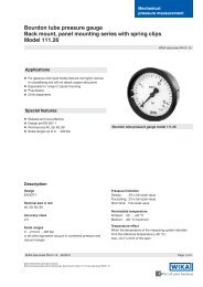
Applications<br />
•<br />
•<br />
•<br />
Suitable for all gaseous and liquid media that will not<br />
obstruct the pressure system<br />
Heating, climatic, ventilating, dust removing technoclogy<br />
Technical building equipment, filter plants,<br />
drinking and service water treatment<br />
Monitoring and control of pumps in pressure boosting<br />
and fire exstinguishing plants<br />
•<br />
Special Features<br />
•<br />
•<br />
•<br />
•<br />
<strong>Differential</strong> pressure measuring ranges from<br />
0 ... 160 mbar<br />
High working pressure (static pressure) up to 25 bar<br />
Overpressure safety either side up to 25 bar<br />
Solid case construction for protection against external<br />
mechanical effects<br />
Integrated pressure equalising valve (option)<br />
•<br />
DELTA-trans with integrated 3½-digit LCD-display and<br />
compression fitting with ferrule (option)<br />
Description<br />
The differential pressure transmitters DELTA-trans are particularly<br />
intended for the measurementof very low differential<br />
pressures with high demands on one-sided overload.<br />
Standard output signals of 4 … 20 mA (2-wire system) or<br />
0 … 20 mA (3-wire system) can be provided from a nonstabilised<br />
DC supply of 10 … 30 V.<br />
As an option, the differential pressure transmitter DELTAtrans<br />
(in 2-wire design; 4 ... 20 mA) may be supplied with an<br />
integrated 3½-digit LCD-display.<br />
Electrical connection is made by means of a cable box with<br />
cable gland M20 x 1.5.<br />
Due to the solid and compact design of the instrument,<br />
the operation requires almost no maintenance even under<br />
arduous industrial service conditions.<br />
<strong>WIKA</strong> Data Sheet PV 17.18 ∙ 12/2009<br />
Page 1 of 4<br />
Data sheets showing similar devices:<br />
DELTA-plus, <strong>Differential</strong> pressure gauges with integrated working pressure gauges; <strong>Model</strong> 702.01.100; see data sheet PM 07.15<br />
DELTA-switch, <strong>Differential</strong> pressure switches; <strong>Model</strong> 851.02.100; see data sheet PV 27.17<br />
DELTA-comb, <strong>Differential</strong> pressure gauges with alarm contacts, and micro switch; <strong>Model</strong> 702.02.100; see data sheet PV 27.16
Specifications DELTA-trans <strong>Model</strong> <strong>891.34.2189</strong><br />
<strong>Differential</strong> pressure range bar 0 ... 0.16 to 0 ... 25<br />
Max. working pressure (stat.) bar 25<br />
Overpressure safety bar Either side max. 25<br />
Process connections (wetted) 2x G ¼ female, lower mount (LM), in-line, axle base 26 mm<br />
(option: other pressure connections male or female or<br />
conpression fitting with ferrule for pipe Ø 6, 8 or 10 mm respectively)<br />
Media chamber (wetted) GD-AISi 12 (Cu) 3.2982, black lacquered<br />
(option GD-AlSi 12 (Cu) HART-COAT-surface protection or stainless steel)<br />
Press. element compress. spring (wetted) Stainless steel 1.4310 or FD SiCr EN 10270-2<br />
Press. element separ. diaphragm (wetted) FPM/FKM fabric back stay (option: NBR)<br />
Links (wetted) Stainless steel 1.4305, FPM/FKM (option: NBR)<br />
Sealings (wetted) FPM/FKM (option: NBR)<br />
Press. equalising valve (option) (wetted) Stainless steel and FPM/FKM<br />
4-way valve manifold (option) (wetted) Cu-alloy or stainless steel, 1x pressure equalising valve, 2x gauge valve,<br />
1x valve for purging or air bleeding<br />
Power supply U B<br />
DC V 10 < U B<br />
≤ 30 (option: LCD-display 14 < U B<br />
≤ 30)<br />
Permissible residual ripple % of span / 10 V ≤ 0.1<br />
Supply voltage effect % ss ≤ 10<br />
Output signal and<br />
permissible max. load R A<br />
Effect of load % of span ≤ 0.1<br />
Response time s Approx. 1 (approx. 50 ms option)<br />
Output signal adjustment<br />
• Zero point, electrical<br />
% of span ±15<br />
• Span, electrical<br />
% of span ±30<br />
Linearity % of span 2.5 (limit point calibration)<br />
(including hysteresis)<br />
Permissible<br />
• Medium temperature °C +80 max.<br />
4 … 20 mA, 2-wire system R A<br />
≤ (U B<br />
- 10 V) / 0.02 A with R A<br />
in Ohm and U B<br />
in Volt<br />
0 … 20 mA, 3-wire system R A<br />
≤ (U B<br />
- 10 V) / 0.02 A with R A<br />
in Ohm and U B<br />
in Volt<br />
Option: 1.6 (limit point calibration)<br />
• Ambient temperature °C -10 … +60 (option LCD-display 0 … +50)<br />
Compensated temperat. range °C -10 … +60 (option LCD-display 0 … +50)<br />
Temperature coefficients in<br />
compensated temperat. range<br />
• average T K<br />
of zero point % of span / 10 K ≤ 0.4<br />
• average T K<br />
of span<br />
% of span / 10 K ≤ 0.4<br />
LCD-display (option)<br />
• Voltage load<br />
DC V 3.5<br />
• Display<br />
3½-digit, height 12.7 mm<br />
• Ambient temperature °C 0 … +50<br />
• Storage temperature<br />
°C -10 … +80<br />
Only with electrical output signal 4 ... 20 mA, 2-wire system<br />
Wiring Terminal box ( screw terminals up to 2.5 mm 2 )<br />
Wiring protection<br />
Protected against reserve polarity and overvoltage<br />
EMC (electromagnetic Interference emission per EN 50 081 - 1 (March 93) and EN 50 081 - 2 (March 94),<br />
compatibility) Interference immunity per EN 50 082 - 2 (March 95)<br />
Ingress protection IP 54 per EN 60 529 / IEC 529 (option: IP 65)<br />
Weight kg Approx. 1.3<br />
Dimensions mm See drawings<br />
Page of 4 <strong>WIKA</strong> Data Sheet PV 17.18 ∙ 12/2009
Approval German Lloyd (option)<br />
Additional or deviating specifications<br />
<strong>Pressure</strong> ranges bar 0 ... 0.25 to 0 ... 10<br />
Output signal<br />
4 ... 20 mA, 2-wire or 0 ... 20 mA, 3-wire, current limit I < 32 mA<br />
Permissible ambient temperatur °C -10 ... +70<br />
EMC (electromagnetic Interference emission per EN 50 081 - 1 (March 93) and EN 50 081 - 2 (March 94),<br />
compatibility) Interference immunity per EN 50 082 - 2 (March 95)<br />
ESD kV ±8 contact discharge IEC 1000-4-2<br />
Electromagnetic fields V/m 10 80 % AM, 1 kHz, 0.01 ... 1000 MHz IEC 1000-4-3<br />
Burst kV ±2 coupling clamp IEC 1000-4-4<br />
Conducted HF-disturbance V 3 80 % AM, 1 kHz, 0.01 ... 1000 MHz IEC 1000-4-6<br />
Surge kV ±0.5 symmetrically IEC 1000-4-5<br />
kV ±1 asymmetrically, R i = 42 Ohm<br />
kV ±1 symmetrically<br />
kV ±2 asymmetrically, R i = 42 Ohm, with surge protection only<br />
e.g. MM-DS/x-NFE(L), firm Dehn & Söhne, or equivalent<br />
Conducted NF-disturbance V eff.<br />
3 0.05 ... 10 kHz IEC 945<br />
Vibration test Fc<br />
2 ... 25 Hz, ±1.6 mm % < 2.5 error IEC 68-2-6<br />
25 ... 100 Hz, 4 g % < 2.5 error<br />
Design and operating principle<br />
Illustration of operating principle<br />
The differential pressure transmitter consists mainly of a<br />
mechanical measuring system (1) with elastic pressure<br />
element (2), magnetic-field-dependent sensor (3) with signal<br />
processing board (4) and case with the connecting parts for<br />
the electronics.<br />
A magnet (5) rigidly coupled to the pressure element influences<br />
the electromagnetic field of the HALL sensor. The<br />
resulting signal is amplified to a standard output signal via<br />
the signal processing board.<br />
For recalibration, zero and span can be adjusted by means<br />
of easily accessable potentiometers (6). 1)<br />
<strong>Pressure</strong> entries identified,<br />
j high pressure, i low pressure<br />
1) Restriction: If an LCD display is integrated, it must be noted that the zero point and<br />
span adjustment is to be used only for recalibration of the measuring range. Changes<br />
of the measuring range made by the user by means of the zero and span adjustment<br />
will not be taken into account by the display. If zero / span adjustments are to be<br />
applied during use, we recommend a display 0 ... 100 %.<br />
2155079.01<br />
Position of the potentiometer<br />
The potentiometers are accessible<br />
after unscrewing the screw plugs<br />
in the top of the casing.<br />
Connection details<br />
The terminal 1 and 5 are briged internally in the<br />
terminal box providing two terminals for the<br />
0 V / S - connection.<br />
4 ... 20 mA 2-wire system 0 ... 20 mA 3-wire system<br />
0 V / S -<br />
0 V / S -<br />
U B<br />
+/ S +<br />
Test -<br />
U B<br />
+<br />
Test +<br />
Test +<br />
S + / Test -<br />
SP Potentiometer for span<br />
NP Potentiometer for zero point<br />
2158991.01<br />
mA<br />
Receiving instrument<br />
(e.g. indicator)<br />
Power supply<br />
Terminal box<br />
mA<br />
Receiving<br />
instrument<br />
(e.g. indicator)<br />
Power supply<br />
Terminal<br />
box<br />
1416324.03<br />
<strong>WIKA</strong> Data Sheet PV 17.18 ∙ 12/2009<br />
Page 3 of 4
Dimensions in mm<br />
Standard version<br />
Option LCD-display<br />
2156921.03<br />
Option<br />
Panel mounting<br />
Option Integrated<br />
pressure equalising valve<br />
Option<br />
4-way valve manifold<br />
Panel cut-out<br />
<strong>Pressure</strong><br />
equalising<br />
valve<br />
Gauge valve,<br />
high pressure<br />
side j<br />
Valve for<br />
purging<br />
or air<br />
bleeding<br />
Gauge valve,<br />
low pressure<br />
side i<br />
Panel<br />
2157322.02<br />
2261804.01<br />
2261821.04<br />
Ordering information<br />
<strong>Model</strong> / Measuring range / Output signal / Process connection / Material of media chamber / Material of seperation<br />
diaphragm and sealings / Options<br />
Modifications may take place and materials specified may be replaced by others without prior notice.<br />
Specifications and dimensions given in this leaflet represent the state of engineering at the time of printing.<br />
Page 4 of 4 <strong>WIKA</strong> Data Sheet PV 17.18 ∙ 12/2009<br />
<strong>WIKA</strong> Alexander Wiegand SE & Co. KG<br />
Alexander-Wiegand-Straße 30<br />
63911 Klingenberg/Germany<br />
Tel. (+49) 9372/132-0<br />
Fax (+49) 9372/132-406<br />
E-mail info@wika.de<br />
www.wika.de<br />
12/2009 GB