Measuring insert for process resistance thermometer ... - WIKA Polska
Measuring insert for process resistance thermometer ... - WIKA Polska
Measuring insert for process resistance thermometer ... - WIKA Polska

Create successful ePaper yourself
Turn your PDF publications into a flip-book with our unique Google optimized e-Paper software.
Electrical<br />
temperature measurement<br />
<strong>Measuring</strong> <strong>insert</strong> <strong>for</strong> <strong>process</strong> <strong>resistance</strong> <strong>thermometer</strong><br />
Model TR12-A<br />
<strong>WIKA</strong> data sheet TE 60.16<br />
Applications<br />
■■<br />
Replacement measuring <strong>insert</strong> <strong>for</strong> servicing<br />
Special features<br />
■■<br />
Application ranges from -200 ... +600 °C<br />
■■<br />
Made of mineral-insulated sheathed cable<br />
■■<br />
Explosion-protected versions<br />
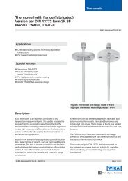
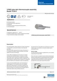
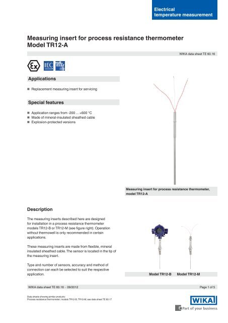
<strong>Measuring</strong> <strong>insert</strong> <strong>for</strong> <strong>process</strong> <strong>resistance</strong> <strong>thermometer</strong>,<br />
model TR12-A<br />
Description<br />
The measuring <strong>insert</strong>s described here are designed<br />
<strong>for</strong> installation in a <strong>process</strong> <strong>resistance</strong> <strong>thermometer</strong><br />
models TR12-B or TR12-M (see figure right). Operation<br />
without thermowell is only recommended in certain<br />
applications.<br />
These measuring <strong>insert</strong>s are made from flexible, mineral<br />
insulated sheathed cable. The sensor is located in the tip of<br />
the measuring <strong>insert</strong>.<br />
Type and number of sensors, accuracy and method of<br />
connection can each be selected to suit the respective<br />
application.<br />
Model TR12-B<br />
Model TR12-M<br />
<strong>WIKA</strong> data sheet TE 60.16 ∙ 09/2012<br />
Page 1 of 5<br />
Data sheets showing similar products:<br />
Process <strong>resistance</strong> <strong>thermometer</strong>; models TR12-B, TR12-M; see data sheet TE 60.17
Explosion protection<br />
Explosion protection Ignition protection type Zone<br />
ATEX Ex i Zone 1, gas [2G Ex ia … Gb]<br />
Zone 1 mounting to zone 0, gas [1/2G Ex ia … Ga/Gb]<br />
Zone 0, gas [1G Ex ia ... Ga]<br />
ATEX Ex d Zone 1, gas [2G Ex d … Gb]<br />
Zone 1 mounting to zone 0, gas [1/2G Ex d … Ga/Gb]<br />
IECEx Ex i Zone 1, gas [2G Ex ia … Gb]<br />
(in conjunction with ATEX)<br />
Zone 1 mounting to zone 0, gas [1/2G Ex ia … Ga/Gb]<br />
Zone 0, gas [1G Ex ia … Ga]<br />
IECEx Ex d Zone 1, gas [2G Ex d … Gb]<br />
(in conjunction with ATEX)<br />
Zone 1 mounting to zone 0, gas [1/2G Ex d … Ga/Gb]<br />
The classification/suitability of the instrument (permissible<br />
power P max as well as the permissible ambient temperature)<br />
<strong>for</strong> the respective category can be seen on the EC-type<br />
examination certificate, the IECEx certificate or in the<br />
operating instructions.<br />
Attention:<br />
Built into a model TR12-B <strong>process</strong> <strong>resistance</strong> <strong>thermometer</strong><br />
- depending on the application - a measuring <strong>insert</strong> with<br />
"intrinsically-safe Ex i" or "flameproof enclosure Ex d" ignition<br />
protection type can be used. One such measuring <strong>insert</strong><br />
suitable <strong>for</strong> Ex d is marked Ex i.<br />
The use of a model TR12-A measuring <strong>insert</strong> in hazardous<br />
areas, without a suitable protective housing, is not permitted!<br />
Example: Model TR12-B<br />
Page 2 of 5 <strong>WIKA</strong> data sheet TE 60.16 ∙ 09/2012
Sensor<br />
<strong>Measuring</strong> element<br />
Pt100 (measuring current: 0.1 ... 1.0 mA) 1)<br />
Connection method<br />
Single element<br />
Dual element<br />
1 x 2-wire<br />
1 x 3-wire<br />
1 x 4-wire<br />
2 x 2-wire<br />
2 x 3-wire<br />
2 x 4-wire 2)<br />
Electrical connection<br />
(Colour code per EN/IEC 60751)<br />
1 x 2-wire<br />
red<br />
white<br />
3160629.06<br />
2 x 2-wire<br />
red<br />
white<br />
black<br />
3160629.06<br />
1 x 3-wire<br />
red<br />
red<br />
white<br />
yellow<br />
red<br />
red<br />
1 x 4-wire<br />
red<br />
red<br />
white<br />
white<br />
2 x 3-wire<br />
white<br />
black<br />
black<br />
yellow<br />
Tolerance value of the measuring element per EN 60751<br />
Class<br />
Sensor construction<br />
wire-wound Thin-film<br />
Class B -200 ... +600 °C -50 ... +500 °C<br />
Class A 3) -100 ... +450 °C 4) -30 ... +300 °C 5)<br />
Class AA 3) -50 ... +250 °C 0 ... +150 °C<br />
1) For detailed specifications <strong>for</strong> Pt100 sensors, see Technical in<strong>for</strong>mation IN 00.17 at<br />
www.wika.com.<br />
2) Not with 3 mm diameter<br />
3) Not at 2-wire connection method<br />
4) -200 … -100 °C, +450 … +600 °C: Class B<br />
5) -50 … -30 °C, +300 … +500 °C: Class B<br />
2 x 4-wire<br />
red<br />
red<br />
white<br />
white<br />
black<br />
black<br />
yellow<br />
yellow<br />
<strong>WIKA</strong> data sheet TE 60.16 ∙ 09/2012<br />
Page 3 of 5
Dimensions in mm<br />
The exchangeable measuring <strong>insert</strong> is made of a vibrationresistant,<br />
sheathed, mineral-insulated cable (MI cable).<br />
Dimensions<br />
<strong>Measuring</strong> <strong>insert</strong> length l 5 ≥ 300 mm<br />
<strong>Measuring</strong> <strong>insert</strong> diameter Ø d<br />
Standard: 3 mm 6)<br />
6 mm<br />
8 mm (with sleeve)<br />
Option (on request):<br />
1/8 inch 6) (3.17 mm)<br />
1/4 inch (6.35 mm)<br />
3/8 inch (9.53 mm)<br />
14048987.01<br />
6) Ø 3 mm not possible with 2 x Pt100, 4-wire<br />
The diameter of the measuring <strong>insert</strong> should be approx. 1 mm<br />
smaller than the bore diameter of the thermowell.<br />
Gaps of more than 0.5 mm between thermowell and the<br />
measuring <strong>insert</strong> will have a negative effect on the heat<br />
transfer, and they will result in unfavourable response<br />
behaviour from the <strong>thermometer</strong>.<br />
When fitting the measuring <strong>insert</strong> into a thermowell, it is<br />
very important to determine the correct <strong>insert</strong>ion length<br />
(= thermowell length <strong>for</strong> bottom thicknesses of ≤ 5.5 mm). In<br />
order to ensure that the measuring <strong>insert</strong> is firmly pressed<br />
down onto the bottom of the thermowell, the <strong>insert</strong> must be<br />
spring-loaded (spring travel: max 20 mm).<br />
Legend:<br />
l 5 <strong>Measuring</strong> <strong>insert</strong> length<br />
Ø d <strong>Measuring</strong> <strong>insert</strong> diameter<br />
Illustration of the spring travel when mounted<br />
(on example of TR12-M)<br />
Attention:<br />
The use of a model TR12-A measuring <strong>insert</strong> is exclusively<br />
allowed with a <strong>resistance</strong> <strong>thermometer</strong> model TR12-B or<br />
TR12-M!<br />
Materials<br />
Material<br />
Sheath material Stainless steel 1.4571<br />
CrNi-Stahl 316<br />
Stainless steel 316L<br />
Page 4 of 5 <strong>WIKA</strong> data sheet TE 60.16 ∙ 09/2012
Operating conditions<br />
Mechanical requirements<br />
Design<br />
Standard<br />
Option<br />
6 g peak-to-peak, wire-wound or thin film measuring<br />
resistor<br />
Vibration resistant sensor tip max. 20 g peak-to-peak,<br />
thin film measuring resistor<br />
High-vibration resistant sensor tips, max 50 g<br />
peak-to-peak, thin film measuring resistor<br />
The replaceable measuring <strong>insert</strong> is made of a vibrationresistant,<br />
sheathed, mineral-insulated cable (MI cable).<br />
Response time (in water, per EN 60751)<br />
t 50 < 10 s<br />
t 90 < 20 s<br />
Specifications <strong>for</strong> measuring <strong>insert</strong> diameter 6 mm<br />
The thermowell required <strong>for</strong> operation increases the<br />
response time dependent upon the actual parameters <strong>for</strong> the<br />
thermowell and the <strong>process</strong>.<br />
Approvals<br />
■■<br />
ATEX<br />
■■<br />
IECEx<br />
Approvals, see local website<br />
Certificates<br />
Certification type<br />
<strong>Measuring</strong><br />
accuracy<br />
Test procedure x x<br />
2.2 Test certificate x x<br />
3.1 Acceptance test certificate x -<br />
DKD/DAkkS calibration certificate x -<br />
The different certifications can be combined with each other.<br />
Material<br />
certificate<br />
Ambient and storage temperature<br />
{-50} -40 ... +80 °C<br />
{} Items in curved brackets are optional extras<br />
Ingress protection<br />
IP 00 per IEC/EN 60529<br />
The measuring <strong>insert</strong>s <strong>for</strong> the model TR12-A are designed <strong>for</strong><br />
mounting into a model TR12-B <strong>resistance</strong> <strong>thermometer</strong>.<br />
These <strong>resistance</strong> <strong>thermometer</strong>s feature connection<br />
housings/cable glands/protective casings which ensure a<br />
high IP protection (see data sheet TE 60.17).<br />
Ordering in<strong>for</strong>mation<br />
Model / Explosion protection / Ignition protection type / Sensor / Sensor specification / Application range of the <strong>thermometer</strong> /<br />
Insertion length / <strong>Measuring</strong> <strong>insert</strong> diameter / Sheath material / Mechanical requirements / Certificates / Options<br />
© 2012 <strong>WIKA</strong> Alexander Wiegand SE & Co. KG, all rights reserved.<br />
The specifications given in this document represent the state of engineering at the time of publishing.<br />
We reserve the right to make modifications to the specifications and materials.<br />
09/2012 GB<br />
<strong>WIKA</strong> data sheet TE 60.16 ∙ 09/2012<br />
Page 5 of 5<br />
<strong>WIKA</strong> Alexander Wiegand SE & Co. KG<br />
Alexander-Wiegand-Straße 30<br />
63911 Klingenberg/Germany<br />
Tel. (+49) 9372/132-0<br />
Fax (+49) 9372/132-406<br />
E-mail info@wika.de<br />
www.wika.de