SIEMON SYSTEM CATALOG
SIEMON SYSTEM CATALOG
SIEMON SYSTEM CATALOG

You also want an ePaper? Increase the reach of your titles
YUMPU automatically turns print PDFs into web optimized ePapers that Google loves.
<strong>SIEMON</strong> <strong>SYSTEM</strong> <strong>CATALOG</strong><br />
N E T W O R K C A B L I N G S O L U T I O N S C A T A L O G<br />
W W W. S I E M O N. C O M
Siemon Innovation<br />
Inspired by our past, focused on the future<br />
In 1903, Carl Siemon launched The Siemon Company on the<br />
strength of his own innovative plastic compounds and soon<br />
began pioneering new telecommunication technologies.<br />
Over a century later that spirit of innovation is still at the core<br />
of everything we do at Siemon – driving us to<br />
develop the most forward-looking, high-quality line of<br />
network cabling solutions in the world.<br />
This catalog represents over a century of Siemon<br />
expertise, detailing the latest innovations and key<br />
products in each of Siemon’s high-performance cabling systems.<br />
New in this edition:<br />
Revolutionary Z-MAX Copper Cabling System<br />
VersaPOD Data Center Cabinet Solution<br />
XLR8 Mechanical Splice Fiber Optic<br />
Termination System<br />
Enhanced and expanded Fiber Optic<br />
Plug and Play Line<br />
MapIT G2 – Next-Generation Intelligent<br />
Infrastructure Management Solution<br />
LockIT Secure Connectivity System
1.0<br />
2.0<br />
3.0<br />
4.0<br />
Category 7 A /ClassF A Products . . . . . . . . . . . . . . . . . . . .<br />
Z-MAX Category 6A Network Cabling Solutions . . . . .<br />
Premium 6 and System 6 UTP . . . . . . . . . . . . . . . . . . . . .<br />
Premium 5 ® F/UTP and System 5e ® . . . . . . . . . . . . . . . .<br />
TABLE OF CONTENTS<br />
5.0<br />
Premium 5 ® and System 5e ® UTP . . . . . . . . . . . . . . . . .<br />
6.0<br />
Fiber Cable Assemblies . . . . . . . . . . . . . . . . . . . . . . . . . .<br />
7.0<br />
Fiber Enclosures and Splicing . . . . . . . . . . . . . . . . . . . .<br />
8.0<br />
MapIT ® G2 Infrastructure Management . . . . . . . . . . . . .<br />
9.0<br />
Faceplates and Mounting Accessories . . . . . . . . . . . . .<br />
10.0<br />
VersaPOD , Racks and Cable Management . . . . . . . . .<br />
11.0<br />
Industrial Product . . . . . . . . . . . . . . . . . . . . . . . . . . . . . . .<br />
12.0<br />
Tools and Testers . . . . . . . . . . . . . . . . . . . . . . . . . . . . . . .<br />
13.0<br />
Glossary/Warranty . . . . . . . . . . . . . . . . . . . . . . . . . . . . . .<br />
14.0<br />
Index . . . . . . . . . . . . . . . . . . . . . . . . . . . . . . . . . . . . . . . . .<br />
www.siemon.com
CATEGORY 7 A /CLASS F A PRODUCTS<br />
Category 7 A /Class F A Products<br />
Exceeding ISO/IEC category 7 A /class F A specifications,<br />
Siemon’s fully shielded TERA end-to-end cabling solution is<br />
the highest-performing, most secure twisted-pair copper<br />
cabling system available. TERA supports performance beyond<br />
10Gb/s and passes stringent TEMPEST security testing.<br />
Beyond industry best speed and best total cost of ownership,<br />
TERA’s unique cable-sharing ability in support of lower speed<br />
applications results in a more “Green” solution and can also<br />
provide up-front savings through the reduction of cable<br />
counts. By combining the use of one TERA outlet dedicated<br />
for high-speed applications of 10Gb/s and beyond and another<br />
for cable sharing of lower speed voice and video applications,<br />
end-users simultaneously benefit from the highest performing<br />
and most cost effective copper solution.<br />
The only non-RJ connector approved as a category 7 A /class<br />
F A interface, TERA fits within a standard RJ45 footprint and is<br />
easily connected to RJ45 equipped electronics via TERA to RJ<br />
patch cords.<br />
SECTION CONTENTS<br />
TERA 4-Pair Outlet . . . . . . . . . . . . . . . . . . . . . . . . . . . . . . . . . . . . . . . .1.2<br />
TERA-MAX ® Patch Panels . . . . . . . . . . . . . . . . . . . . . . . . . . . . . . . . . . .1.3<br />
TERA Patch Cords . . . . . . . . . . . . . . . . . . . . . . . . . . . . . . . . . . . .1.4 – 1.5<br />
TERA Video Baluns . . . . . . . . . . . . . . . . . . . . . . . . . . . . . . . . . . . . . . . .1.5<br />
TERA S/FTP Trunking Cable Assemblies . . . . . . . . . . . . . . . . . . . . . . . .1.6<br />
TERA S/FTP 1000 MHz Cables (US) . . . . . . . . . . . . . . . . . . . . . . . . . . .1.7<br />
TERA S/FTP 1000 MHz Cables (International) . . . . . . . . . . . . . . . . . . . .1.8<br />
1.0 www.siemon.com
TERA Outlet<br />
Invented by Siemon in 1999 and subsequently chosen as an<br />
industry standard interface for category 7/class F and<br />
category 7 A /class F A , the Siemon TERA outlet is by far the<br />
highest performing twisted-pair copper connector in the<br />
world. When installed as part of a TERA solution, each pair<br />
delivers 1.2 GHz per pair — exceeding category 7 A /class F A<br />
specifications. This extra bandwidth supports demanding<br />
applications like broadband video, with an upper frequency<br />
requirement of 862 MHz.<br />
1<br />
4<br />
6<br />
7<br />
8<br />
Easy Installation<br />
CPT-T tool reduces preparation and<br />
termination time.<br />
Mounting Options<br />
The TERA outlet is compatible with TERA-<br />
MAX ® patch panels and all MAX series<br />
faceplates.<br />
CATEGORY 7 A /CLASS F A<br />
® PRODUCTS<br />
2<br />
3<br />
5<br />
Quick-Ground <br />
Termination<br />
No additional steps required for<br />
termination. Cable shield is automatically<br />
terminated within the outlet without<br />
additional steps or tools.<br />
Bend Relief — Rear boot provides bend relief for cable exiting the<br />
plug and outlet<br />
Fully Shielded — Terminates fully shielded (F/FTP and S/FTP)<br />
cable — virtually eliminates alien crosstalk<br />
Shielded Termination — Connector automatically assures proper<br />
termination of cable shield — no additional processes required for<br />
grounding cable<br />
Compact Design — Slim, compact design allows outlets to be<br />
side-stacked and inserted from either the front or rear of faceplates<br />
1 5<br />
2<br />
3<br />
4<br />
6<br />
7<br />
8<br />
Hinged Door — Outlets include a hinged door to prevent exposure<br />
to dust and other contaminates<br />
Quadrant Isolation — Shielded quadrant design fully isolates<br />
pairs for optimum NEXT performance<br />
Application Sharing — TERA’s ability to support multiple<br />
applications over a single 4-pair cable and outlet can save<br />
significant material and installation costs<br />
TEMPEST Security Tested — The TERA system is the first and<br />
only copper system to pass TEMPEST emissions testing by an<br />
independent, NSA certified lab, Dayton T. Brown Inc.<br />
www.siemon.com<br />
1.1
CATEGORY 7 A /CLASS F A PRODUCTS<br />
TERA 4-Pair Outlet<br />
TERA outlets are the industry’s highest performing network cabling<br />
connectors. Outlets accept 1-, 2- and 4-pair plugs and terminate fully shielded<br />
category 7 and 7 A cables. TERA outlets can be used in both the work area and<br />
in the telecommunications room.<br />
Part #<br />
Description<br />
T7F-01-1. . . . . . . . . . . . . . . . . . TERA 4-pair outlet with black door, latch and boot. Compatible with 0.64-0.55mm<br />
(22-23 AWG) solid S/FTP and F/FTP cable<br />
TERA Cable Sharing<br />
Up to four simultaneous applications can be served from a single 4-pair, S/FTP cable and<br />
TERA outlet, saving significant materials, labor, pathway and rack space.<br />
Broadband Video<br />
(1-pair)<br />
Voice<br />
(1-pair)<br />
One TERA replaces four 1-pair analog voice outlets — perfect for call or fax centers.<br />
10/100 Ethernet<br />
(2-pair)<br />
1.2 www.siemon.com
TERA-MAX Patch Panels<br />
TERA-MAX 19 inch patch panels provide outstanding performance<br />
and reliability in a shielded, high-density modular solution. As<br />
outlets are snapped into place, resilient ground tabs assure that each<br />
outlet is properly grounded. No secondary outlet grounding<br />
operations are required, reducing overall installation time.<br />
1<br />
2<br />
3<br />
1 2<br />
Standard Fit — Panels can be mounted<br />
directly on standard 19 inch relay rack or<br />
cabinet<br />
Durable — Lightweight, high strength steel<br />
with black or metallic finish<br />
High Density — 24 10Gb/s ports in only<br />
1U — up to 96 ports with cable sharing<br />
3<br />
4<br />
5<br />
6<br />
6<br />
4<br />
Installation Friendly — Individual modules<br />
snap into place, providing integrated<br />
grounding without additional steps<br />
Port Identification — Bold port numbering<br />
enables quick identification of outlets<br />
Angled TERA-MAX — Allows direct routing<br />
of cables to vertical managers, eliminating<br />
the need for horizontal cable managers<br />
5<br />
Cable Management<br />
Integral rear cable manager facilitates the<br />
orderly routing of horizontal cables as well<br />
as maintaining proper bend radius for<br />
optimum performance.<br />
Slim Design<br />
Use TERA outlets in TERA-MAX patch panel<br />
for telecommunications room applications.<br />
Integrated Grounding<br />
Panels feature integrated grounding via<br />
resilient ground tabs engaged during<br />
module insertion.<br />
CATEGORY 7 A /CLASS F A PRODUCTS<br />
TERA-MAX PATCH PANELS<br />
Part #<br />
Description<br />
TM-PNLZ-24-01 . . . . . . . . .24-port TERA-MAX panel, black, 1U<br />
TM-PNLZ-24 . . . . . . . . . . . .24-port TERA-MAX panel, metallic, 1U<br />
TM-PNLZA-24-01 . . . . . . . .24-port Angled TERA-MAX panel, black, 1U<br />
TM-PNLZA-24 . . . . . . . . . .24-port Angled TERA-MAX panel, metallic, 1U<br />
Panels include designation labels, cable ties and mounting hardware.<br />
Note: 1U = 44.5mm (1.75 in.)<br />
www.siemon.com<br />
1.3
CATEGORY 7 A /CLASS F A PRODUCTS<br />
TERA - Patch Cords<br />
Part of the TERA cabling solution, TERA-to-TERA patch cords exceed<br />
bandwidth of category 7 A /class F A specifications when combined with<br />
the TERA outlet. TERA delivers up to 1.2 GHz of bandwidth per pair,<br />
providing the extra bandwidth for demanding applications like Broadband<br />
Video, with an upper frequency requirement of 862 MHz. Facilitated<br />
by 1- and 2-pair patch cords, TERA’s extended performance also<br />
supports cable sharing — the simultaneous convergence of video,<br />
voice and data onto a single 4-pair cable and outlet.<br />
2<br />
3<br />
4<br />
5<br />
6<br />
Standard Footprint<br />
ISO recognized interface allows TERA cords<br />
and outlets to fit within a standard RJ45<br />
footprint.<br />
Fully Compatible With<br />
Active Electronics<br />
TERA to RJ45 patch cords allow the TERA<br />
system to be easily connected to RJ45<br />
equipped active electronics.<br />
1<br />
1<br />
2<br />
3<br />
Standard Compliant Interface —<br />
Recognized within ISO/IEC 11801 Ed. 2.0<br />
4-Pair TERA - to - TERA supports category<br />
7 A /class F A performance to 10Gb/s and<br />
beyond<br />
2-Pair TERA - to - Screened Category 5e<br />
MC ® modular plug for 10/100 Ethernet, VoIP<br />
and video over IP<br />
4<br />
5<br />
6<br />
4-Pair TERA - to - Screened Augmented<br />
Category 6A MC modular plug for 1G/10G<br />
Ethernet performance<br />
1-Pair TERA - to - TERA for analog voice<br />
and video patching. Video balun cord also<br />
available<br />
1-Pair TERA - to - RJ11 for analog voice<br />
Cable Sharing<br />
Multiple applications can be run over one<br />
4-pair cable and outlet, saving significant<br />
material and installation cost.<br />
TERA FIELD-TERMINATED PLUG<br />
TERA 4-pair plugs can be used to terminate horizontal cable in consolidation point applications. Plugs<br />
terminate fully shielded category 7 and 7A solid cable.<br />
Part #<br />
T7P4-B(XX)-1<br />
Description<br />
4-pair TERA plug with colored boot.<br />
Compatible with 0.64 – 0.55mm (22 – 23 AWG) solid S/FTP and F/FTP cable<br />
Use (XX) to specify boot color: 01 = black, 02 = white, 03 = red, 05 = yellow, 06 = blue, 07 = green<br />
1.4 www.siemon.com
TERA Patch Cords<br />
TERA CATEGORY 7 A PATCH CORDS<br />
Category 7 A compatible, TERA-to-TERA, LS0H cable<br />
assembly, ivory jacket, colored boot.<br />
Plug Type:<br />
1 = 1-Pair<br />
4 = 4-Pair<br />
Cord Length:<br />
01 = 1m (3.28 ft.)<br />
02 = 2m (6.56 ft.)<br />
Boot Color:<br />
01 = Black<br />
02 = White<br />
03 = Red<br />
03 = 3m (9.84 ft.)<br />
05 = 5m (16.4 ft.)<br />
05 = Yellow<br />
06 = Blue<br />
07 = Green<br />
TERA CATEGORY 6A PATCH CORDS<br />
Augmented Category 6A, TERA-to-Screened RJ-45 modular plug, LS0H<br />
cable assembly, ivory jacket, colored boot.<br />
Plug Type:<br />
A = T568B<br />
T = T568A<br />
T(X)-(XX)M-B(XX)L<br />
T4(X)-S(XX)M-B(XX)L<br />
Boot Color:<br />
01 = Black<br />
02 = White<br />
03 = Red<br />
05 = Yellow<br />
06 = Blue<br />
07 = Green<br />
TERA CATEGORY 5e COMPATIBLE PATCH CORDS<br />
TERA-to-Screened RJ-45, or TERA-to- 6 position (Voice) modular plug,<br />
LS0H cable assembly, ivory jacket, colored boot.<br />
Plug Type:<br />
2E2 = 2-Pair, RJ-45,<br />
10/100BASE-T<br />
2UT = 2-Pair, RJ-45,<br />
Token Ring<br />
1U1 = 1-Pair*, UTP,<br />
6-position, Voice<br />
T(XXX)-(XX)M-B(XX)L<br />
Cord Length:<br />
01 = 1m (3.28 ft.)<br />
02 = 2m (6.56 ft.)<br />
Boot Color:<br />
01 = Black<br />
02 = White<br />
03 = Red<br />
03 = 3m (9.84 ft.)<br />
05 = 5m (16.4 ft.)<br />
05 = Yellow<br />
06 = Blue<br />
07 = Green<br />
CATEGORY 7 A /CLASS F A PRODUCTS<br />
Cord Length:<br />
01 = 1m (3.28 ft.)<br />
02 = 2m (6.56 ft.)<br />
03 = 3m (9.84 ft.)<br />
05 = 5m (16.4 ft.)<br />
CLIP-(XX) . . . . . . . . . . . . . . . . . . Color coding clip, bag of 25<br />
Clip Color<br />
01 = Black<br />
02 = White<br />
03 =Red<br />
04 = Gray<br />
05 = Yellow<br />
06 = Blue<br />
07 = Green<br />
09 = Orange<br />
TERA VIDEO BALUN CORDS<br />
TERA CATV baluns provide the optimum solution for the transmission of TV or CATV signals over structured cabling systems that were historically limited to voice<br />
and data transmission. These products convert the unbalanced TV signals designed for coaxial cabling (75 Ω impedance) to balanced signals (100 Ω impedance)<br />
as required for transmission over twisted pair (balanced) cabling. The TERA CATV adapters are specified and useable to 862 MHz. The 1-pair TERA to PAL and<br />
TERA to "F" patch cords utilize an integrated balun. The 1-pair shielded TERA to shielded RJ45 patch cord allows connection to third-party RJ45 baluns.<br />
Part #<br />
Description<br />
T1VC-(XX)M-B01L . . . . . . . . . . . 1-pair TERA-to-PAL connector, LS0H cable assembly, gray jacket<br />
T1VF-(XX)M-B01L . . . . . . . . . . . 1-pair TERA-to-F connector, LS0H cable assembly, gray jacket<br />
T1S4V-(XX)M-B01L . . . . . . . . . . 1-pair shielded TERA-to-RJ45 patch cord<br />
Use (XX) to specify length: 01 = 1m (3.28 ft.), 1.5 = 1.5m (4.92 ft.), 02 = 2m (6.56 ft.),<br />
03 = 3m (9.84 ft.), 05 = 5m (16.4 ft.) T1VF-(XX)M-B01L T1S4V-(XX)M-B01L<br />
www.siemon.com<br />
1.5
CATEGORY 7 A /CLASS F A PRODUCTS<br />
TERA - S/FTP Trunking Cable<br />
Assemblies<br />
Siemon’s TERA copper trunking cable assemblies provide an efficient and<br />
cost effective alternative to individual field-terminated components.<br />
Combining factory terminated and tested TERA outlets and fully shielded<br />
Siemon category 7 A cable, Siemon TERA trunking cable assemblies offer<br />
industry leading performance to 10Gb/s and beyond. Standard<br />
configurations also help maintain consistent cable layout, facilitate efficient<br />
moves, adds and changes and significantly reduce scrap versus typical field<br />
installation. Modular design, in conjunction with reduced scrap, makes<br />
trunks the most “Green” method for copper cabling installations.<br />
1<br />
5<br />
2 3<br />
4<br />
Data Centers<br />
Ideal for data center, raised floor and ladder<br />
rack environments enabling up to 75% faster<br />
deployment time. Well organized cable<br />
bundles improve cable management and air<br />
flow<br />
Simple, Snap-In<br />
Installation<br />
Straight Cut aligns TERA outlets for optimal<br />
snap in installation into TERA-MAX ® patch<br />
panels and allows left, right or center exit.<br />
1<br />
2<br />
3<br />
Proper Orientation — Each leg is<br />
labeled for proper outlet orientation<br />
Fully Shielded Cable — Utilizes high<br />
quality category 7 A S/FTP Siemon cable<br />
Factory Terminated and Tested —<br />
Utilizes TERA outlets, factory terminated<br />
and tested for performance to 10Gb/s<br />
and beyond<br />
4<br />
5<br />
Identification — Each cable assembly is<br />
coded with a unique identification<br />
number for administrative purposes<br />
Breakout Kit — Unique breakout kit<br />
creates optimal cable orientation and<br />
limits cable crossing<br />
Protective Packaging<br />
Each assembly is packaged individually to<br />
protect factory terminations.<br />
TERA S/FTP TRUNKING CABLE ASSEMBLIES<br />
6 Leg Double-Ended Trunking Cable Assemblies:<br />
Part #<br />
Description<br />
TJRD6E-F7F7(XXX)F . . . . . . . . . Riser rated (CMR), blue jacket, 1000MHz<br />
TJPD6E-F7F7(XXX)F . . . . . . . . . Plenum rated (CMP), blue jacket, 1000MHz<br />
TJLD8E-F7F7(XXX)F . . . . . . . . . LS0H rated (IEC 60332-1), violet jacket, 1000MHz<br />
STRAIGHT CUT<br />
Use (XXX) to specify length:<br />
009-295 ft. in increments of 3 feet<br />
Other lengths and configurations available upon request.<br />
Note: These products are made to order. Call for lead time and part number availability in your region.<br />
1.6 www.siemon.com
TERA S/FTP 1000 MHz<br />
4-Pair Cable (US)<br />
COMPLIANCE<br />
• ISO/IEC 11801:2002 (Category 7)<br />
• ISO/IEC 11801 Amendment 1 (draft)<br />
• IEC 61156-5:2002 (Category 7)<br />
• IEC 61156-5 Ed 2.0 (Category 7 A )<br />
• UL CMR and CSA FT4<br />
• UL CMP and CSA FT6<br />
CABLE CONSTRUCTION<br />
• S/FTP<br />
• 0.64mm (0.025 in.) (22 AWG) solid bare copper<br />
• 8.9mm (0.35 in.) [CMR], 8.4mm (0.33 in.) [CMP]<br />
max jacket diameter<br />
• Pairs individually shielded with aluminum-polyester foil<br />
• Overall tinned copper braid<br />
ELECTRICAL SPECIFICATIONS<br />
DC Resistance<br />
CATEGORY 7 A /CLASS F A PRODUCTS<br />
TERA S/FTP 1000 MHz 4-Pair<br />
Cable (International)<br />
COMPLIANCE<br />
• ISO/IEC 11801:2002 (Category 7)<br />
• ISO/IEC 11801 Amendment 1 (draft)<br />
• IEC 61156-5:2002 (Category 7)<br />
• IEC 61156-5 Ed 2.0 (Category 7 A )<br />
• LS0H: IEC 60332-1, IEC 60754, and IEC 61034<br />
CABLE CONSTRUCTION<br />
• S/FTP<br />
• 0.57mm (0.023 in.) (23 AWG) solid bare copper<br />
• 8.4mm (0.33 in.) max jacket diameter<br />
• Pairs individually shielded with aluminum-polyester foil<br />
• Overall tinned copper braid<br />
ELECTRICAL SPECIFICATIONS<br />
DC Resistance<br />
CATEGORY 7 A /CLASS F A PRODUCTS<br />
www.siemon.com<br />
1.9
Z-MAX NETWORK CABLING SOLUTIONS<br />
Siemon’s Z-MAX Network<br />
Cabling Solutions<br />
The development of the Z-MAX line began with a simple goal - design and build the best<br />
RJ-45 based cabling solution - period.<br />
And “best” was not a vague metric. Z-MAX was built to be best across the board:<br />
Highest performance margins across all critical transmission parameters<br />
Fastest, easiest and most reliable termination process<br />
<br />
Superior transmission consistency<br />
The best customer focused usability, efficiency and ergonomic features<br />
To meet these goals, we did what we have done for over a century - innovate.<br />
As you explore the Z-MAX line, you’ll see Siemon innovation at every turn. From our<br />
patent-pending Zero-Cross TM termination to the exclusive PCB-based smart plug technology<br />
integrated into every Z-MAX cord to our hybrid flat/angled outlets to the easy-to-use Z-TOOL,<br />
no opportunity to improve this family was overlooked.<br />
SECTION CONTENTS<br />
Z-MAX Introduction . . . . . . . . . . . . . . . . . . . . . . . . . . . . . . . . . .2.1 - 2.3<br />
Z-MAX 6A Shielded Overview . . . . . . . . . . . . . . . . . . . . . . . . . . . . . . . .2.4<br />
Z-MAX 6A Shielded Outlets . . . . . . . . . . . . . . . . . . . . . . . . . . . . . . . . .2.5<br />
Z-MAX 6A Shielded Modular Cords . . . . . . . . . . . . . . . . . . . . . . . . . . .2.6<br />
Category 6A Shielded BladePatch . . . . . . . . . . . . . . . . . . . . . . . . . . . .2.7<br />
Z-MAX 6A Shielded Patch Panels . . . . . . . . . . . . . . . . . . . . . . . . . . . . .2.8<br />
TERA-MAX Patch Panels . . . . . . . . . . . . . . . . . . . . . . . . . . . . . . . . . . . .2.9<br />
Z-MAX 6A Preterminated Shielded Trunk Cable . . . . . . . . . . . . . . . . .2.10<br />
Category 6A F/UTP Cable (North America) . . . . . . . . . . . . . . . . . . . .2.11<br />
Category 6A F/UTP Cable (South/Central America) . . . . . . . . . . . . . .2.12<br />
Z-MAX 6A UTP Overview . . . . . . . . . . . . . . . . . . . . . . . . . . . . . . . . .2.12<br />
Z-MAX 6A UTP Outlets . . . . . . . . . . . . . . . . . . . . . . . . . . . . . . . . . . .2.13<br />
Z-MAX 6A UTP Modular Cords . . . . . . . . . . . . . . . . . . . . . . . . . . . . .2.14<br />
Category 6A UTP BladePatch . . . . . . . . . . . . . . . . . . . . . . . . . . . . . .2.15<br />
Z-MAX 6A UTP Patch Panels . . . . . . . . . . . . . . . . . . . . . . . . . . . . . . .2.16<br />
Z-MAX 6A UTP Trunk Cable Assembly . . . . . . . . . . . . . . . . . . . . . . . .2.17<br />
Category 6A UTP Cable (Americas) . . . . . . . . . . . . . . . . . . . . . . . . . .2.18<br />
2.0 www.siemon.com
DON’T BLINK<br />
Best-in-class category 6A performance for UTP and Shielded in as little as 60 seconds<br />
1<br />
2<br />
0:30 sec.<br />
Prep cable and place into Z-MAX’s<br />
patent-pending Zero-Cross TM lacing cap.<br />
Close hinged cable retention/grounding clip.<br />
0:45 sec.<br />
Lace conductor pairs into color-coded<br />
linear lacing channels and trim excess.<br />
Z-MAX NETWORK CABLING SOLUTIONS<br />
3<br />
0:60 sec.<br />
Insert lacing cap into Z-MAX outlet and<br />
terminate with the one-step Z-TOOL TM .<br />
Complete!<br />
www.siemon.com<br />
2.1
Z-MAX NETWORK CABLING SOLUTIONS<br />
Siemon Innovations that make it possible. . .<br />
Highest-Performing Category 6A Systems<br />
IL<br />
NEXT<br />
PSNEXT<br />
ACR-F<br />
PSACR-F<br />
RL<br />
PSANEXT<br />
PSAACR-F<br />
ACR-N<br />
PSACR-N<br />
Z-MAX<br />
6A UTP<br />
3 %<br />
3.0 dB<br />
3.5 dB<br />
7 dB<br />
10 dB<br />
3 dB<br />
1 dB<br />
1 dB<br />
6 dB<br />
6.5 dB<br />
Z-MAX<br />
6A F/UTP<br />
3 %<br />
3.0 dB<br />
3.5 dB<br />
7 dB<br />
10 dB<br />
3 dB<br />
10 dB<br />
5 dB<br />
6 dB<br />
6.5 dB<br />
Performance based on use of 2M cords and 24 cords and 24 port /1U density.<br />
Because we continually improve our product, Siemon reserves the right to<br />
change specifications and availability without prior notice.<br />
With Z-MAX, Siemon has shattered the RJ-45 barrier.<br />
We have achieved best-in-class performance<br />
through an innovative “matched” system which<br />
combines an optimally tuned plug with a higher<br />
performance outlet.<br />
<br />
<br />
<br />
<br />
<br />
<br />
Best UTP and F/UTP category 6A margins<br />
Leading performance on all parameters, not just NEXT<br />
Exceptional alien crosstalk performance<br />
TIA channel, link compliant<br />
ISO channel, link (draft) compliant<br />
Consistent, superior performance,<br />
eliminates marginal reporting (*PASS)<br />
Patent-Pending Smart Plug Technology<br />
A critical element of Z-MAX systems’ exceptional performance is our smart-plug technology.<br />
The Z-MAX smart plug contains a tuned printed circuit board (PCB), normally only found in outlets,<br />
to achieve high performance tuning. This advancement in miniaturization has packaged the<br />
tuning capability and consistency of a PCB in an industry standard RJ-45 footprint, giving the<br />
Z-MAX patch cord unsurpassed performance capabilities.<br />
Eliminates pair<br />
untwist required in<br />
standard RJ-45 plugs<br />
<br />
<br />
<br />
<br />
<br />
Patent pending PCB-based plug enables performance levels not<br />
possible with traditional cords<br />
Narrower NEXT range provides capability to tune to higher channel<br />
performance levels<br />
Advanced contact technology and automated assembly results in<br />
decreased performance variability compared with crimp-type plugs<br />
Smart-Plug is fully backwards-compatible and standards compliant<br />
PCB-based contacts eliminate pair-crossing condition present in<br />
traditional cords<br />
2.2 www.siemon.com
Zero-Cross Terminations<br />
The crossing of cable pairs has long been recognized as a source of variability and performance<br />
degradation in connector systems. The linear design of the Z-MAX termination module allows<br />
conductors to feed naturally into position without the need for pair crossing.<br />
Linear design dramatically speeds and simplifies cable prep and conductor<br />
alignment<br />
Removes a significant source of noise and interference present in all other<br />
RJ-45 outlets<br />
Maintains and protects cable pair structure for optimized transmission<br />
performance consistency<br />
Intuitive cable lacing significantly minimizes miswires that lead to costly<br />
reworks<br />
Diagonal IDC Contact Orientation<br />
Siemon engineers thought “outside of the box” when they developed our diagonally-oriented IDC contact<br />
technology. This unique configuration places contacts on a single plane yet varies the alignment of each<br />
individual contact within the Z-MAX outlet. This design provides distinct performance benefits compared<br />
with traditional rectangular contact layouts.<br />
Z-MAX NETWORK CABLING SOLUTIONS<br />
<br />
<br />
<br />
<br />
Maximizes pair-to-pair separation from adjacent outlets to miminize alien crosstalk<br />
even in the most dense category 6A patching environments<br />
Enhances NEXT performance within outlets<br />
Limits untwist of pairs at termination to maximize cable performance<br />
Fully enclosed IDC’s eliminates exposure of uninsulated conductors<br />
www.siemon.com<br />
2.3
Z-MAX 6A SHIELDED<br />
Z-MAX 6A Shielded System<br />
Features and Benefits<br />
Combining consistent best-in-class performance, unparalleled usability and speed of termination<br />
with the security and robust noise immunity of a shielded cabling system, Siemon’s Z-MAX 6A<br />
shielded end-to-end solution represents the cutting edge of category 6A cabling. The Z-MAX 6A<br />
shielded system provides the highest margins on all TIA and ISO performance requirements for<br />
category 6A/class E A , including critical alien crosstalk parameters.<br />
Siemon’s Z-MAX 6A shielded channel consists of the shielded Z-MAX 6A outlet, Siemon category 6A<br />
F/UTP cable and Z-MAX patch panels as well as shielded, stranded or solid cord options.<br />
Standards Compliance<br />
ISO/IEC 11801: 2002 Amendment 1 (Class E A )<br />
TIA/EIA-568-B.2-10<br />
IEEE 802.3an<br />
UL-listed<br />
Z-MAX 6A F/UTP Performance<br />
GUARANTEED 4-CONNECTOR CHANNEL MARGINS TO ISO/IEC 11801: 2002 AMENDMENT 1 (Class E A )<br />
PARAMETER<br />
VALUE<br />
IL 3 %<br />
NEXT<br />
3 dB<br />
PSNEXT<br />
3.5 dB<br />
ACR-F<br />
7 dB<br />
PSACR-F<br />
10 dB<br />
RL<br />
3 dB<br />
PSANEXT<br />
10 dB<br />
PSAACR-F<br />
5 dB<br />
ACR-N<br />
6 dB<br />
PSACR-N<br />
6 dB<br />
2.4 www.siemon.com
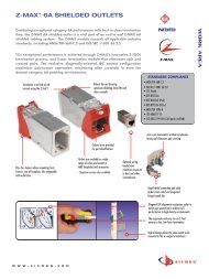
Z-MAX 6A Shielded Outlets<br />
The shielded Z-MAX outlet offers best-in-class performance in every critical specification,<br />
exceeding all category 6A performance requirements, including alien crosstalk. Its innovative<br />
features not only speed and simplify termination, but remove installation variability for<br />
consistently high and repeatable performance - every termination, every time!<br />
3<br />
2<br />
4<br />
Flexibility and<br />
Simplified Ordering<br />
A single hybrid outlet supports<br />
both angled and flat mounting<br />
orientations<br />
Z-MAX 6A SHIELDED<br />
1<br />
2<br />
3<br />
1<br />
Fastest Termination Time – Zero-Cross<br />
termination module and Z-TOOL<br />
termination process combine for<br />
best-in-class termination time<br />
High-Visibility Icon System – Printed<br />
icons allow designation for voice / data<br />
applications and also provide an<br />
additional color coding option<br />
Compact – Slim and side-stackable for<br />
high-density applications. Supports<br />
“pass-thru” feature to mount from the<br />
front or rear of a faceplate<br />
5<br />
4<br />
5<br />
6<br />
Guided Termination Features – Linear<br />
lacing channels guide correct<br />
conductor placement while 2-sided<br />
color-coding provide wiring verification<br />
before and after lacing<br />
Color Coding Capability – Bezel allows<br />
outlets to be color coded for customer<br />
identification to match faceplates and<br />
other mounting accessories<br />
Robust Hinged Cable Retention/Grounding<br />
– Clip accommodates multiple cable<br />
diameters<br />
6<br />
Enhanced Shielding<br />
Effectiveness<br />
High level of shielded effectiveness<br />
exceeds ISO 360 degree shielding<br />
requirements via die cast housing and<br />
hinged cable retention/grounding clip<br />
100% jack-to-jack<br />
plastic isolation<br />
Plastic bezels prevent contact between<br />
metal housings when side stacking to<br />
ensure ground quality and ANEXT<br />
performance<br />
Quick-Ground<br />
Termination<br />
Cable shield is automatically terminated<br />
to the outlet without additional steps<br />
Ordering Information:<br />
Z6A-S(X)(XX) - Shielded Z-MAX 6A outlet, T568A/B<br />
Mounting Style<br />
(Blank) = Hybrid Flat/Angled<br />
K = Keystone<br />
Bezel Color<br />
01 = Black<br />
02 = White<br />
03 = Red<br />
04 = Gray<br />
05 = Yellow<br />
06 = Blue<br />
07 = Green<br />
09 = Orange<br />
20 = Ivory<br />
80 = Light Ivory<br />
Hybrid<br />
Keystone<br />
Add “B” to end of part number for bulk project pack of 100 modules (hybrid outlets include icons).<br />
Add “D” to end of part number for spring door option.<br />
Outlet terminates S/FTP, F/FTP and F/UTP cable constructions with 23 – 26<br />
AWG (0.64 – 0.51mm) solid and 26 AWG (0.48mm) stranded conductors,<br />
with up to 0.60mm diameter conductors and up to 1.48mm diameter over<br />
insulation.<br />
Note: Z-MAX 6A Shielded outlets utilize MAX faceplates<br />
Z-MAX outlets utilize the Z-TOOL termination tool.<br />
Each Z-MAX 6A hybrid outlet includes 1 printed icon set<br />
with the following color/print options.<br />
Additional color options available.<br />
1 - Red Data<br />
1 - Blue Data<br />
1 - Bezel Color-matching Data<br />
1 - White Blank<br />
1 - Red Voice<br />
1 - Blue Voice<br />
1 - Bezel Color-Matching Voice<br />
1 - Bezel Color-Matching Blank<br />
Front<br />
Rear<br />
www.siemon.com<br />
2.5
Z-MAX 6A SHIELDED<br />
Z-MAX 6A Shielded<br />
Modular Cords<br />
Combining the unparalleled performance of an exclusive PCB-based<br />
plug, noise-resistant shielded construction and a host of innovative<br />
user friendly features, the shielded Z-MAX 6A modular cords are the ultimate<br />
category 6A cord. All cords are 100% factory-tested to ensure<br />
performance and compliance.<br />
5<br />
4<br />
Excellent Bend Relief<br />
Boot ensures proper bend relief<br />
and maintains minimum bend<br />
radius requirements<br />
3<br />
1<br />
2<br />
6<br />
Colored Clips<br />
Removable clips allow field color<br />
coding even when cords are<br />
connected<br />
1<br />
2<br />
3<br />
Integrated PCB – PCB equipped smart<br />
plugs optimize signal tuning for<br />
exceptional transmission<br />
Superior Performance Consistency –<br />
Rear contacts maintain pair twist to point<br />
of termination and provide robust strain<br />
relief<br />
Fixed Front Contacts – Ensure proper<br />
mating with outlets to eliminate the<br />
performance variability of traditional<br />
crimp-style terminations<br />
4<br />
5<br />
6<br />
High Performance Cable – Patch cords<br />
feature category 7 S/FTP stranded cable<br />
for optimal transmission performance<br />
while eliminating alien cross-talk<br />
Low Profile Boot Design – Optimizes<br />
side-stackability of patch cords and<br />
allows use in even the most dense<br />
patching environments<br />
Cantilevered Latch – Allows latch<br />
activation from further back on the boot<br />
for superior accessibility in high density<br />
environments<br />
Solid Cord Option<br />
Solid F/UTP assemblies are<br />
available for consolidation point<br />
and equipment cord applications<br />
Ordering Information:<br />
ZM6A-S(XX)-(XX) . . . . . . . . . Z-MAX 6A shielded (S/FTP), double-ended,<br />
stranded modular cord, clear boot, T568A/B, LS0H<br />
Length<br />
03 = 3 ft.*<br />
05 = 5 ft.*<br />
07 = 7 ft.<br />
10 = 10 ft.<br />
15 = 15 ft.<br />
20 = 20 ft.<br />
Jacket Color<br />
01 = Black<br />
02 = White<br />
03 = Red<br />
04 = Gray<br />
05 = Yellow<br />
06 = Blue<br />
07 = Green<br />
09 = Orange<br />
* 7ft. or longer cords required for Z-MAX 6A Warranty<br />
Add “B” to end of part number for bulk project pack of 100 cords.<br />
ZC6A-S(XX)(X)-(X)(X) . . . . . . Z-MAX 6A shielded (F/UTP) solid modular cord,<br />
blue jacket, clear boot<br />
Plugs<br />
Length<br />
10 = 10 ft.<br />
20 = 20 ft.<br />
30 = 30 ft.<br />
40 = 40 ft.<br />
50 = 50 ft.<br />
60 = 60 ft.<br />
Wiring<br />
A = T568B<br />
T = T568A<br />
Jacket Type<br />
P = Plenum<br />
R = Riser<br />
(Blank) = Single-ended<br />
D = Double-ended (T568A/B)<br />
CLIP-(XX) . . . . . . . . . . . . . . . . . . Color coding clip, bag of 25<br />
Clip Color<br />
01 = Black<br />
02 = White<br />
03 = Red<br />
04 = Gray<br />
05 = Yellow<br />
06 = Blue<br />
07 = Green<br />
09 = Orange<br />
2.6 www.siemon.com
Category 6A Shielded<br />
BladePatch Modular Cords<br />
Category 6A shielded BladePatch patch cord offers a unique category<br />
6A solution for high-density patching environments. It features an<br />
innovative push-pull boot design to control the latch, enabling easy<br />
access and removal of the cord in tight-fitting areas. The BladePatch<br />
cord is ideal for patching blade servers, patch panels, or any equipment<br />
with high density RJ-45 outlets.<br />
1<br />
2<br />
3<br />
2<br />
Push-Pull Boot<br />
Activates Latch<br />
3<br />
1<br />
Revolutionary Design — Patented pushpull<br />
latch design eliminates need to defeat<br />
thumb latch used in standard modular plug<br />
designs. Enables easy access and removal in<br />
high density patching environments<br />
Universal Wiring — Compatible with<br />
T568A/B wiring schemes<br />
Snagless — Push-pull design eliminates<br />
external thumb latch which can snag and<br />
break<br />
4<br />
5<br />
4<br />
5<br />
6<br />
6<br />
Low Profile Boot Design — Optimizes sidestackability<br />
of patch cords and allows use in<br />
even the most dense equipment<br />
High Performance — Cords feature<br />
category 7 S/FTP stranded cable for optimal<br />
transmission performance while eliminating<br />
alien crosstalk<br />
Backwards Compatible — With category<br />
5e/class D and category 6/class E systems<br />
and components<br />
Universal Compatibility<br />
Fits within any standard RJ-45 outlet.<br />
Revolutionary Latch<br />
Simply push the boot forward to latch into<br />
the outlet and pull back to release.<br />
High Density<br />
The push-pull design enables easy access<br />
and removal via the push/pull boot in<br />
tight-fitting areas.<br />
CATEGORY 6A SHIELDED BLADEPATCH <br />
Ordering Information:<br />
Shielded category 6A BladePatch LS0H, double-ended, RJ-45 modular patch cord<br />
with push-pull latching design, color matching cord/boot, T568A/B.<br />
10GBPS-(XX)M-(XX)L<br />
Cord Length:<br />
01 = 1m (3.3 ft.)<br />
1.5 = 1.5m (4.9 ft.)<br />
02 = 2m (6.6 ft.)<br />
03 = 3m (9.8 ft.)<br />
04 = 4m (13.1 ft.)<br />
05 = 5m (16.4 ft.)<br />
Cord Color:<br />
01 = Black<br />
02 = White<br />
03 = Red<br />
04 = Gray<br />
05 = Yellow<br />
06 = Blue<br />
07 = Green<br />
The use of Category 6A shielded BladePatch modular cords<br />
will provide Category 6A channel performance if used in a<br />
Z-MAX 6A system. Z-MAX 6A warranty margins do not apply.<br />
www.siemon.com<br />
2.7
Z-MAX 6A SHIELDED<br />
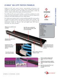
Z-MAX 6A Shielded Patch Panels<br />
Z-MAX patch panels provide outstanding performance and aesthetics<br />
in a shielded, high-density modular solution. The Z-MAX<br />
panels provide rapid and reliable installation by accelerating<br />
outlet mounting, grounding, and cable tie-down operations.<br />
In addition to traditional 24 port / 1U flat and angled versions, the<br />
Z-MAX shielded panels are also available in 48 port / 1U configurations<br />
for ultra high density installations.<br />
1<br />
Installation Friendly<br />
Quick-Snap feature allows Z-MAX panel<br />
outlets to quickly be inserted and removed<br />
2<br />
4<br />
3<br />
Trunking Applications<br />
Combine Z-MAX trunk assemblies (with<br />
panel outlets) and empty Z-MAX panels<br />
for rapid data center deployment<br />
5<br />
1<br />
2<br />
3<br />
High-Density – Provides up to 48 ports<br />
in just 1U to reduce valuable rack/cabinet<br />
space consumption<br />
Port Identification – High visibility<br />
magnifying labeling system enables quick<br />
identification of outlets<br />
Durable – Lightweight, high strength<br />
steel with black finish and scratch/fade<br />
resistant port marking<br />
4<br />
5<br />
Flexible – Both flat and angled panel<br />
options<br />
Integrated Quick-Ground TM – Panels<br />
feature embedded conductive strips to<br />
automatically ground Z-MAX modules to<br />
panel upon insertion<br />
Kits<br />
Panels available as complete kits<br />
including patch panel, Z-MAX panel<br />
outlets and all necessary accessories.<br />
Empty panels are also available for<br />
use with Z-MAX trunk assemblies<br />
Ordering Information:<br />
Z6AS-PNL(X)-24(X)...........24 Port, Z-MAX 6A shielded patch panel, 1U, black<br />
Mounting Style<br />
(Blank) = Flat<br />
A = Angled<br />
Outlets<br />
K = Kit w/ 24 Z-MAX panel outlets<br />
E = Empty (no outlets) for use with trunks<br />
Z6AS-PNL(X)-U48(X).........48 Port, Z-MAX 6A shielded patch panel, 1U, black<br />
Mounting Style<br />
(Blank) = Flat<br />
A = Angled<br />
Outlets<br />
K = Kit w/ 48 Z-MAX panel outlets<br />
E = Empty (no outlets)<br />
Panel Accessories<br />
Z-PNL-PL24...........Patch panel label sheet, numbered 1 to 24, bag of 100<br />
Z-PNL-PL48...........Patch panel label sheet, numbered 25 to 48, bag of 100<br />
Z-PNL-PS ..............Patch panel label holder, bag of 25<br />
Z6A-SP .................Z-MAX 6A shielded panel outlet<br />
Panels include: Cable Ties, Icon/Label Holders, Labels, #6 AWG Grounding<br />
Lug, and Mounting Hardware<br />
Note: Z-MAX shielded panels designed for use with Z-MAX<br />
shielded panel outlets only<br />
2.8 www.siemon.com
TERA ® -MAX Patch Panels<br />
TERA-MAX patch panels provide outstanding performance and reliability<br />
in a shielded, high-density modular solution. As outlets are snapped into<br />
place, resilient ground tabs assure that each outlet is properly grounded<br />
for maximum protection from outside interference. No secondary outlet<br />
grounding operations are required, reducing overall installation time.<br />
4<br />
Integrated Grounding<br />
Panels feature integrated grounding via<br />
resilient Quick-Ground tabs automatically<br />
engaged during Z-MAX outlet insertion.<br />
Z-MAX 6A SHIELDED<br />
1<br />
2<br />
3<br />
Single Outlet Solution<br />
Hybrid (flat/angled) shielded Z-MAX outlets<br />
used in the work area are required for use<br />
in TERA-MAX panels creating a common<br />
outlet solution for all locations<br />
1<br />
High Density – 24 10G/bs ports in<br />
only 1U<br />
3<br />
Durable – Lightweight, high strength<br />
steel with black or metallic finish<br />
2<br />
Port Identification — Bold port<br />
numbering enables quick identification of<br />
outlets<br />
4<br />
Angled TERA-MAX – Allows direct<br />
routing of cables to vertical managers,<br />
eliminating the need for horizontal cable<br />
managers<br />
Future Flexibility<br />
TERA-MAX panels also accept TERA<br />
outlets to support potential future<br />
infrastructure upgrades<br />
Ordering Information:<br />
Part #<br />
Description<br />
TM-PNLZ-24-01 . . . . . . . . .24-port TERA-MAX panel, black, 1U<br />
TM-PNLZ-24 . . . . . . . . . . . .24-port TERA-MAX panel, metallic, 1U<br />
TM-PNLZA-24-01 . . . . . . . .24-port Angled TERA-MAX panel, black, 1U<br />
TM-PNLZA-24 . . . . . . . . . .24-port Angled TERA-MAX panel, metallic, 1U<br />
Panels include designation labels, cable ties and mounting hardware.<br />
Note: TERA-MAX panels are designed for use with hybrid (flat/angled) shielded Z-MAX outlets. Also compatible with TERA outlets<br />
www.siemon.com<br />
2.9
Z-MAX 6A SHIELDED<br />
Z-MAX 6A Shielded<br />
Trunking Cable Assemblies<br />
Featuring factory terminated and tested shielded Z-MAX outlets and<br />
Siemon category 6A F/UTP cable, Z-MAX 6A shielded copper trunking<br />
cable assemblies were designed with data center applications in mind,<br />
providing high-performance category 6A performance in a quickly<br />
implemented, efficient and cost effective alternative to individual<br />
field-terminated components.<br />
1<br />
Data Centers<br />
Ideal for data center, raised floor and ladder<br />
rack environments enabling up to 75% faster<br />
deployment time. Well organized cable<br />
bundles improve cable management and air<br />
flow<br />
1<br />
2 3<br />
4<br />
5 6<br />
Simple Installation<br />
Pre-terminated Z-MAX panel outlets utilize the<br />
Quick-Snap feature for easy installation and<br />
removal from Z-MAX panels<br />
1<br />
2<br />
3<br />
Proper Orientation – Each leg is labeled<br />
for proper outlet orientation<br />
Category 6A F/UTP Cable – Utilizes<br />
high quality Siemon category 6A F/UTP<br />
cable<br />
Factory Terminated and Tested –<br />
Utilizes shielded Z-MAX outlet, factory<br />
terminated and tested for high<br />
performance<br />
4<br />
5<br />
6<br />
Identification – Each cable assembly is<br />
coded with a unique identification<br />
number for administrative purposes<br />
Breakout Kit – Unique breakout kit<br />
creates optimal cable orientation and<br />
limits cable crossing<br />
Quick-Ground TM – Shielded Z-MAX 6A<br />
panel outlets are automatically grounded<br />
upon insertion into Z-MAX panels<br />
Protective Packaging<br />
Each assembly is packaged individually to<br />
protect factory terminations<br />
Ordering Information:<br />
TE(X)D6E-(XXXX)(XXX)F . . . . . . . 6 Leg Solid Cable Double-Ended Trunking Cable Assembly<br />
Cable Jacket<br />
R = Riser rated (CMR), blue jacket<br />
P = Plenum rated (CMP), blue jacket<br />
Standard wiring is T568B.<br />
Other lengths and configurations available upon request.<br />
Length<br />
009-295 = Indicate length in feet<br />
(increments of 3 feet)<br />
Connector Types<br />
P7P7 = Z-MAX panel outlets for use with Z-MAX panels<br />
H1H1 = Z-MAX hybrid (flat/angled) outlets for use with TERA-MAX panels<br />
P7J7 = Z-MAX panel outlets to Z-MAX plugs<br />
H1J7 = Z-MAX hybrid (flat/angled) outlets to Z-MAX plugs<br />
STRAIGHT CUT<br />
Note: These products are made to order. Call for lead time and part number<br />
availability in your region.<br />
2.10 www.siemon.com
Siemon Category 6A F/UTP<br />
4-Pair Cable (North America)<br />
CABLE CONSTRUCTION<br />
• F/UTP<br />
• 0.57mm (0.023 in.) (23 AWG) solid<br />
bare copper<br />
• 7.4mm (0.29 in.) max jacket<br />
diameter<br />
• Central isolation member<br />
• Shield is an aluminum foil tape<br />
enclosing a 0.51mm (0.20 in.)<br />
(24 AWG) tinned copper drain wire<br />
COMPLIANCE<br />
• ISO/IEC 11801:2002,<br />
Amendment 2<br />
(Category 6 A draft)<br />
• TIA-568-B.2-10<br />
• UL CMR and CSA FT4<br />
• UL CMP and CSA FT6<br />
PHYSICAL PROPERTIES<br />
CMP<br />
CMR<br />
Pulling Tension (max) 110N (25 lbf) 110N (25 lbf)<br />
Bend Radius (min) 50mm (2.0 in.) 50mm (2.0 in.)<br />
Installation Temperature 0 to 60°C (+32 to 140°F) 0 to 60°C (+32 to 140°F)<br />
Storage Temperature -20 to 75°C (-4 to 167°F) -20 to 75°C (-4 to 167°F)<br />
Operating Temperature -20 to 60°C (-4 to 140°F) -20 to 60°C (-4 to 140°F)<br />
Z-MAX 6A SHIELDED<br />
Ordering Information:<br />
9A6(X)4-A5-(XX)-R1A . . . . . . . . 305m (1000 ft.) Reel (North America Only)<br />
Jacket Material<br />
P = Plenum (CMP, CSA FT6)<br />
R = Riser (CMR, CSA FT4)<br />
Jacket Color<br />
02 = White<br />
04 = Grey<br />
05 = Yellow<br />
06 = Blue<br />
TRANSMISSION PERFORMANCE GUARANTEED WORST CASE <strong>SIEMON</strong> TYPICAL<br />
Frequency Insertion Loss NEXT PS NEXT ACR PSACR ACR-F PS ACR-F Return Loss Propagation<br />
(MHz) (dB) (dB) (dB) (dB) (dB) (dB) (dB) (dB) Delay<br />
(ns)<br />
1.0 2.0 1.8 74.3 86.0 72.3 82.3 72.3 84.2 70.3 80.5 67.8 91.0 64.8 85.0 20.0 33.0 570 545<br />
4.0 3.8 3.4 65.3 77.0 63.3 73.3 61.5 73.6 59.5 69.9 55.8 79.0 52.8 73.0 23.0 35.5 552 527<br />
10.0 6.0 5.4 59.3 71.0 57.3 67.3 53.3 65.6 51.3 61.9 47.8 71.0 44.8 65.0 25.0 38.0 545 520<br />
16.0 7.6 6.9 56.2 68.0 54.2 64.2 48.7 61.1 46.7 57.3 43.7 67.0 40.7 61.0 25.0 35.2 543 518<br />
20.0 8.5 7.7 54.8 67.0 52.8 62.8 46.3 59.3 44.3 55.1 41.8 65.0 38.8 59.0 25.0 35.0 542 517<br />
31.25 10.7 9.9 51.9 64.0 49.9 59.9 41.2 54.1 39.2 50.0 37.9 61.0 34.9 55.0 23.6 33.1 540 515<br />
62.5 15.4 14.3 47.4 59.0 45.4 55.4 32.0 44.7 30.0 41.1 31.9 55.0 28.9 49.0 21.5 32.2 539 514<br />
100.0 19.8 18.1 44.3 56.0 42.3 52.0 24.5 37.9 22.5 33.9 27.8 51.0 24.8 45.0 20.1 31.6 538 513<br />
200.0 29.0 27.3 39.8 52.0 37.8 47.8 10.8 24.7 8.8 20.5 21.8 45.0 18.8 39.0 18.0 29.8 537 512<br />
250.0 32.8 31.1 38.3 50.0 36.3 46.0 5.5 18.9 3.5 14.9 19.8 43.0 16.8 37.0 17.3 28.7 536 511<br />
300.0 36.4 35.0 37.1 49.0 35.1 45.0 0.7 14.0 -1.3 10.0 18.3 38.0 15.3 35.0 16.8 28.0 536 511<br />
400.0 43.0 40.0 35.3 47.0 33.3 43.0 -7.7 7.0 -9.7 3.0 15.8 36.0 12.8 33.0 15.9 27.1 536 511<br />
500.0 48.9 42.0 33.8 47.0 31.8 42.0 -15.1 5.0 -17.1 0.0 13.8 34.0 10.8 32.0 15.2 26.0 536 510<br />
550.0* 51.8 43.0 33.2 46.0 31.2 42.0 -18.6 3.0 -20.6 -1.0 13.0 33.0 10.0 31.0 14.9 26.0 536 510<br />
625.0* 55.8 44.9 32.4 46.0 30.4 41.0 -23.5 1.1 -25.5 -3.9 11.9 33.0 8.9 29.0 14.5 25.0 535 505<br />
750.0* 62.3 49.0 31.2 45.0 29.2 41.0 -31.1 -4.0 -33.1 -8.0 10.3 32.0 7.3 27.0 14.0 25.0 535 504<br />
*Values for frequencies beyond industry requirements are for information only<br />
All performance based on 100 meters (328 ft.).<br />
www.siemon.com<br />
2.11
Z-MAX 6A SHIELDED<br />
Siemon Category 6A F/UTP<br />
4-Pair Cable (South/Central America)<br />
CABLE CONSTRUCTION<br />
• F/UTP<br />
• 0.57mm (0.023 in.) (23 AWG)<br />
solid bare copper<br />
• 7.4mm (0.29 in.) max jacket<br />
diameter<br />
• Central isolation member<br />
• Shield is an aluminum foil tape<br />
enclosing a 0.51mm (0.20 in.) (24<br />
AWG) tinned copper drain wire<br />
COMPLIANCE<br />
• ISO/IEC 11801:2002,<br />
Amendment 2<br />
(Category 6 A draft)<br />
• TIA-568-B.2-10<br />
• UL CM and IEC 60332-1<br />
• UL CMR and CSA FT4<br />
• LS0H IEC 60332-1, IEC 60754,<br />
IEC 61034<br />
PHYSICAL PROPERTIES<br />
CMP<br />
CMR<br />
Pulling Tension (max) 110N (25 lbf) 110N (25 lbf)<br />
Bend Radius (min) 50mm (2.0 in.) 50mm (2.0 in.)<br />
Installation Temperature 0 to 60°C (+32 to 140°F) 0 to 60°C (+32 to 140°F)<br />
Storage Temperature -20 to 75°C (-4 to 167°F) -20 to 75°C (-4 to 167°F)<br />
Operating Temperature -20 to 60°C (-4 to 140°F) -20 to 60°C (-4 to 140°F)<br />
Ordering Information:<br />
9A6(X)4-A5 . . . . . . . . . . . . . . . . 305m (1000 ft.) Reel (South/Central America Only)<br />
Jacket Material<br />
M = PVC (CM, IEC 60332-1), Gray Jacket<br />
R = Riser (CMR, CSA FT4), Blue Jacket<br />
L = LS0H (IEC 60332-1), Violet Jacket<br />
TRANSMISSION PERFORMANCE TIA/EIA & ISO/IEC (draft) <strong>SIEMON</strong> TYPICAL<br />
Frequency Insertion Loss NEXT PS NEXT ACR PSACR ACR-F PS ACR-F Return Loss Propagation<br />
(MHz) (dB) (dB) (dB) (dB) (dB) (dB) (dB) (dB) Delay<br />
(ns)<br />
1.0 2.0 1.8 74.3 86.0 72.3 82.3 72.3 84.2 70.3 80.5 67.8 91.0 64.8 85.0 20.0 33.0 570 545<br />
4.0 3.8 3.4 65.3 77.0 63.3 73.3 61.5 73.6 59.5 69.9 55.8 79.0 52.8 73.0 23.0 35.5 552 527<br />
10.0 6.0 5.4 59.3 71.0 57.3 67.3 53.3 65.6 51.3 61.9 47.8 71.0 44.8 65.0 25.0 38.0 545 520<br />
16.0 7.6 6.9 56.2 68.0 54.2 64.2 48.7 61.1 46.7 57.3 43.7 67.0 40.7 61.0 25.0 35.2 543 518<br />
20.0 8.5 7.7 54.8 67.0 52.8 62.8 46.3 59.3 44.3 55.1 41.8 65.0 38.8 59.0 25.0 35.0 542 517<br />
31.25 10.7 9.9 51.9 64.0 49.9 59.9 41.2 54.1 39.2 50.0 37.9 61.0 34.9 55.0 23.6 33.1 540 515<br />
62.5 15.4 14.3 47.4 59.0 45.4 55.4 32.0 44.7 30.0 41.1 31.9 55.0 28.9 49.0 21.5 32.2 539 514<br />
100.0 19.8 18.1 44.3 56.0 42.3 52.0 24.5 37.9 22.5 33.9 27.8 51.0 24.8 45.0 20.1 31.6 538 513<br />
200.0 29.0 27.3 39.8 52.0 37.8 47.8 10.8 24.7 8.8 20.5 21.8 45.0 18.8 39.0 18.0 29.8 537 512<br />
250.0 32.8 31.1 38.3 50.0 36.3 46.0 5.5 18.9 3.5 14.9 19.8 43.0 16.8 37.0 17.3 28.7 536 511<br />
300.0 36.4 35.0 37.1 49.0 35.1 45.0 0.7 14.0 -1.3 10.0 18.3 38.0 15.3 35.0 16.8 28.0 536 511<br />
400.0 43.0 40.0 35.3 47.0 33.3 43.0 -7.7 7.0 -9.7 3.0 15.8 36.0 12.8 33.0 15.9 27.1 536 511<br />
500.0 48.9 42.0 33.8 47.0 31.8 42.0 -15.1 5.0 -17.1 0.0 13.8 34.0 10.8 32.0 15.2 26.0 536 510<br />
550.0* 51.8 43.0 33.2 46.0 31.2 42.0 -18.6 3.0 -20.6 -1.0 13.0 33.0 10.0 31.0 14.9 26.0 536 510<br />
625.0* 55.8 44.9 32.4 46.0 30.4 41.0 -23.5 1.1 -25.5 -3.9 11.9 33.0 8.9 29.0 14.5 25.0 535 505<br />
750.0* 62.3 49.0 31.2 45.0 29.2 41.0 -31.1 -4.0 -33.1 -8.0 10.3 32.0 7.3 27.0 14.0 25.0 535 504<br />
*Values for frequencies beyond industry requirements are for information only<br />
All performance based on 100 meters (328 ft.).<br />
2.12 www.siemon.com
Z-MAX 6A UTP System Features<br />
and Benefits<br />
Siemon’s Z-MAX 6A UTP solution was developed from the ground up with a single goal: shattering the<br />
limitations of category 6A UTP cabling as we know it today. Combining patent-pending PCB-based smart<br />
plugs, optimized outlets, reduced diameter cable and high-density patch panels, the Z-MAX 6A UTP<br />
system provides outstanding margin on all TIA and ISO performance requirements for category 6A/class<br />
E A , including critical alien crosstalk parameters.<br />
Z-MAX 6A UTP<br />
And, the innovative Z-TOOL TM termination process eliminates the variability of field terminations, providing<br />
faster, more user-friendly and less-error-prone category 6A UTP installations.<br />
Standards Compliance<br />
ISO/IEC 11801: 2002 Amendment 1 (Class E A )<br />
TIA-568-B.2-10<br />
IEEE 802.3an<br />
UL-listed<br />
PARAMETER<br />
VALUE<br />
IL 3 %<br />
NEXT<br />
3.0 dB<br />
PSNEXT<br />
3.5 dB<br />
ACR-F<br />
2 dB<br />
PSACR-F<br />
5 dB<br />
RL<br />
3 dB<br />
PSANEXT<br />
1 dB<br />
PSAACR-F<br />
1 dB<br />
ACR-N<br />
6 dB<br />
PSACR-N<br />
6.5 dB<br />
Performance based on use of 2M cords and 24 cords and 24 port /1U density.<br />
Because we continually improve our product, Siemon reserves the right to change specifications and availability without prior notice.<br />
www.siemon.com<br />
2.13
Z-MAX 6A UTP<br />
Z-MAX 6A UTP Outlets<br />
The category 6A UTP Z-MAX outlet offers best-in-class performance in<br />
every critical specification, exceeding all category 6A performance<br />
requirements, including alien crosstalk. Its innovative features not only<br />
accelerate and simplify termination, but remove installation variability for<br />
consistently high and repeatable performance - every termination,<br />
every time!<br />
4<br />
2<br />
Optimized For Alien<br />
Crosstalk Isolation<br />
Diagonal IDC alignment maximizes<br />
outlet to outlet pair separation to<br />
archive AXT performance in highdensity,<br />
environments<br />
3<br />
5<br />
1<br />
6<br />
1<br />
2<br />
Fastest Termination Time – Zero-Cross <br />
termination module and 2-step Z-TOOL <br />
termination process combine for<br />
best-in-class termination time<br />
High-Visibility Icon System – Printed<br />
icons allow designation for voice / data<br />
applications and also provide an additional<br />
color coding option<br />
4<br />
5<br />
Guided Termination Features – Lacing<br />
channels guide correct conductor<br />
placement while 2-sided color-coding<br />
provide wiring verification before and after<br />
lacing<br />
Enclosed IDC Terminations – IDC<br />
terminations are fully enclosed in the outlet<br />
housing for robust protection<br />
3<br />
Compact –Slim and side-stackable for<br />
high-density applications. Supports “passthru”<br />
feature to mount from the front or<br />
rear of a faceplate<br />
6<br />
Robust Hinged Cable Retention – Hinged<br />
clip accommodates multiple cable<br />
diameters<br />
Flexibility and<br />
Simplified Ordering<br />
A single hybrid outlet supports both<br />
angled and flat mounting<br />
orientations<br />
Ordering Information:<br />
Z6A-(X)(XX) . . . . . . . . . . .UTP Z-MAX 6A outlet, T568A/B<br />
Mounting Style<br />
(Blank) = Hybrid Flat/Angled<br />
K = Keystone<br />
Bezel Color<br />
01 = Black<br />
02 = White<br />
03 = Red<br />
04 = Gray<br />
05 = Yellow<br />
06 = Blue<br />
07 = Green<br />
09 = Orange<br />
20 = Ivory<br />
80 = Light Ivory<br />
Hybrid<br />
Keystone<br />
Add “B” to end of part number for bulk project pack of 100 modules (hybrid outlets include icons).<br />
Add “D” to end of part number for spring door option.<br />
Outlet terminates UTP cable constructions with 23 – 26 AWG (0.64 – 0.51mm)<br />
solid and 26 AWG (0.48mm) stranded conductors, with up to 0.60mm<br />
diameter conductors and up to 1.48mm diameter over insulation.<br />
Note: Z-MAX 6A UTP outlets utilize 10G MAX faceplates and<br />
cannot be side-stacked in standard MAX faceplates.<br />
Z-MAX outlets utilize the Z-TOOL termination tool.<br />
See Page 12.3.<br />
Each Z-MAX 6A UTP hybrid flat/angled outlet includes<br />
1 printed icon set with the following color/print options.<br />
Additional color options available.<br />
1 - Red Data<br />
1 - Blue Data<br />
1 - Bezel Color-matching Data<br />
1 - White Blank<br />
1 - Red Voice<br />
1 - Blue Voice<br />
1 - Bezel Color-Matching Voice<br />
1 - Bezel Color-matching Blank<br />
Front<br />
Rear<br />
2.14 www.siemon.com
Z-MAX 6A UTP<br />
Modular Cords<br />
Combining the unparalleled performance of an exclusive PCB-based<br />
smart plug, alien crosstalk resistant construction and a host of<br />
innovative user-friendly features, the Z-MAX 6A UTP modular cords<br />
set the bar for category 6A UTP patching.<br />
3<br />
6<br />
4<br />
5<br />
2<br />
1<br />
100% Factory-Tested<br />
Cords are 100% transmission tested to<br />
ensure compliance with applicable<br />
standards requirements<br />
Colored Clips<br />
Removable clips allow field color coding<br />
even when cords are connected<br />
CATEGORY 6A UTP BLADEPATCH <br />
1<br />
Integrated PCB – PCB equipped smart plugs<br />
optimize signal tuning for exceptional<br />
transmission<br />
4<br />
Low Profile Boot Design – Optimizes sidestackability<br />
of modular cords and allows use<br />
in even the most dense equipment<br />
2<br />
3<br />
Superior Performance Consistency –<br />
Precision PCB-based conductor terminations<br />
eliminate the performance variability of<br />
traditional direct wire to contacts<br />
High Performance Cable – Z-MAX 6A UTP<br />
cords feature dual jacket construction for<br />
excellent alien crosstalk performance<br />
5<br />
6<br />
Cantilevered Latch Guard – Allows latch<br />
activation from further back on the boot for<br />
superior accessibility in high density<br />
environments<br />
Solid Cord Option – Solid UTP cords are<br />
available for consolidation point and<br />
equipment cord applications<br />
Excellent Bend Relief<br />
Boot ensures proper bend relief and maintains<br />
minimum bend radius requirements<br />
Ordering Information:<br />
ZM6A-(XX)-(XX) . . . . . . . . . . . . . Z-MAX 6A UTP, double-ended, stranded modular<br />
cord, clear boot, T568A/B, CMG<br />
ZC6A-(XX)(X)-(X)(X) . . . . . . . . . . Z-MAX 6A UTP, solid modular cord, blue jacket, clear boot<br />
Length<br />
03 = 3 ft.*<br />
05 = 5 ft.*<br />
07 = 7 ft.<br />
10 = 10 ft.<br />
15 = 15 ft.<br />
20 = 20 ft.<br />
Jacket Color<br />
01 = Black<br />
02 = White<br />
03 = Red<br />
04 = Gray<br />
05 = Yellow<br />
06 = Blue<br />
07 = Green<br />
* 7ft. or longer cords required for Z-MAX 6A Warranty<br />
Add “B” to end of part number for bulk project pack of 100 cords.<br />
Length<br />
10 = 10 ft.<br />
20 = 20 ft.<br />
30 = 30 ft.<br />
40 = 40 ft.<br />
50 = 50 ft.<br />
60 = 60 ft.<br />
Wiring<br />
A = T568B<br />
T = T568A<br />
Jacket Type<br />
P = Plenum<br />
R = Riser<br />
Plugs<br />
(Blank) = Single-ended<br />
D = Double-ended (T568A/B)<br />
CLIP-(XX) . . . . . . . . . . . . . . . . . . Color coding clip, bag of 25<br />
Clip Color<br />
01 = Black 03 = Red<br />
02 = White 04 = Gray<br />
05 = Yellow<br />
06 = Blue<br />
07 = Green<br />
09 = Orange<br />
www.siemon.com<br />
2.15
Z-MAX 6A UTP<br />
Category 6A UTP<br />
BladePatch ® Modular Cords<br />
Siemon’s Category 6A UTP BladePatch patch cord offers a unique category<br />
6A solution for high-density patching environments. It features an<br />
innovative push-pull boot design to control the latch, enabling easy access<br />
and removal of the cord in tight-fitting areas.<br />
The BladePatch cord is ideal for patching blade servers, patch panels, or<br />
any equipment with high density RJ-45 outlets.<br />
Universal Compatibility<br />
Fits within any standard RJ-45 outlet.<br />
2<br />
Push-Pull Boot<br />
Activates Latch<br />
3<br />
5<br />
6<br />
Revolutionary Latch<br />
Simply push the boot forward to latch into the<br />
outlet and pull back to release.<br />
1<br />
4<br />
1<br />
2<br />
3<br />
Revolutionary Design — Patented push-pull<br />
latch design eliminates need to defeat thumb<br />
latch used in standard modular plug designs.<br />
Enables easy access and removal in high<br />
density patching environments<br />
Universal Wiring — Compatible with<br />
T568A/B wiring schemes<br />
Snagless — Push-pull design eliminates<br />
external thumb latch which can snag and<br />
break<br />
4<br />
5<br />
6<br />
Low Profile Boot Design — Optimizes sidestackability<br />
of patch cords and facilitates use<br />
in equipment with extremely high port density<br />
Optimized Bend Radius — Patent pending<br />
design removes outer jacket layer at plug<br />
ends to reduce bend radius and improve<br />
flexibility when entering and exiting switches<br />
and patch panels<br />
High Performance — Cords feature dual<br />
jacket construction for excellent alien crosstalk<br />
performance<br />
High Density<br />
The push-pull design enables easy access and<br />
removal via the boot in tight-fitting areas.<br />
Ordering Information:<br />
Category 6A BladePatch double ended, 4-pair UTP stranded modular cord with push-pull latching<br />
design, color matching cord/boot, T568A/B, CMG<br />
BP6A-(XX)-(XX)<br />
Cord Length:<br />
03 = 0.9m (3 ft.)<br />
05 = 1.5m (5 ft.)<br />
07 = 2.1m (7 ft.)<br />
10 = 3.1m (10 ft.)<br />
15 = 4.6m (15 ft.)<br />
20 = 6.1m (20 ft.)<br />
Cord Color:<br />
01 = Black<br />
02 = White<br />
03 = Red<br />
04 = Gray<br />
05 = Yellow<br />
06 = Blue<br />
07 = Green<br />
The use of Category 6A UTP BladePatch modular cords will<br />
provide Category 6A channel performance if used in a<br />
Z-MAX 6A system. Z-MAX 6A warranty margins do not apply.<br />
2.16 www.siemon.com
Z-MAX 6A UTP Patch Panels<br />
Z-MAX patch panels provide outstanding 10 Gb/s performance and<br />
aesthetics in a high-density, modular UTP solution. The Z-MAX UTP<br />
panels provide rapid and reliable installation by accelerating module<br />
mounting, and cable tie-down operations.<br />
In addition to traditional 24-port / 1U flat and angled versions, the<br />
Z-MAX UTP panels are also available in 48-port / 1U configurations for<br />
ultra high density installations.<br />
Kits<br />
Panels available as complete kits including<br />
patch panel, Z-MAX panel outlets, Z-TOOL<br />
and all necessary accessories. Empty panels<br />
are also available for use with Z-MAX trunk<br />
assemblies<br />
Z-MAX 6A UTP<br />
1<br />
2<br />
3 4<br />
5<br />
Ideal for Trunking<br />
Applications<br />
Combine Z-MAX trunk assemblies (with<br />
panel outlets) and empty Z-MAX panels for<br />
rapid data center deployment<br />
1<br />
2<br />
3<br />
High Density — Provides 48 ports in just<br />
1U while still meeting strict category 6A<br />
Alien Crosstalk parameter<br />
Installation Friendly — Quick-Snap feature<br />
allows panel outlets to quickly be snapped<br />
into place<br />
Port Identification —High visibility<br />
magnifying labeling system enables quick<br />
identification of outlets<br />
4<br />
5<br />
Durable — Lightweight, high strength steel<br />
with black finish and scratch/fade resistant<br />
port marking<br />
Aesthetics — The Z-MAX panel provides a<br />
clean front surface to improve the<br />
installation appearance<br />
Integrated Cable<br />
Management<br />
Ensures proper cable management<br />
practices for all installations, critical to<br />
category 6A performance<br />
Ordering Information:<br />
Z6A-PNL(X)-24(X).............24-Port, Z-MAX 6A UTP Patch Panel, 1U, Black<br />
Mounting Style<br />
(Blank) = Flat<br />
A = Angled<br />
Outlets<br />
K = Kit w/ 24 Z-MAX Panel Outlets<br />
E = Empty (no outlets) for use with trunks<br />
Panel Accessories<br />
Z6A-PNL(X)-U48(X)...........48-Port, Z-MAX 6A UTP Patch Panel, 1U, Black<br />
Mounting Style<br />
(Blank) = Flat<br />
A = Angled<br />
Outlets<br />
K = Kit w/ 48 Z-MAX Panel Outlets<br />
E = Empty (no outlets) for use with trunks<br />
Z-PNL-PL24................Patch panel label sheet, numbered 1 to 24, bag of 100<br />
Z-PNL-PL48................Patch panel label sheet, numbered 25 to 48, bag of 100<br />
Z-PNL-PS ...................Patch panel label holder, bag of 25<br />
Z6A-P .........................Z-MAX 6A UTP panel outlet<br />
Note: Z-MAX UTP panels are designed for use with Z-MAX UTP panel outlets only<br />
Panels include: Cable Ties, Icon/Label Holders, Labels and Mounting Hardware<br />
www.siemon.com<br />
2.17
Z-MAX 6A UTP<br />
Z-MAX 6A UTP<br />
Trunking Cable Assemblies<br />
Siemon’s Z-MAX 6A UTP trunking cable assemblies provide an easily<br />
installed and cost effective alternative to individual field-terminated<br />
channels. Combining factory terminated and tested Z-MAX outlets<br />
with Siemon’s category 6A UTP cable in a high-performance modular<br />
cable assembly, Z-MAX 6A UTP trunking cable assemblies are<br />
designed to simplify the installation of category 6A systems in data<br />
centers and other high-density high-performance environments.<br />
Data Centers<br />
Ideal for data center, raised floor and ladder<br />
rack environments enabling up to 75% faster<br />
deployment time. Well organized cable<br />
bundles improve cable management and air<br />
flow<br />
3<br />
1<br />
5<br />
2<br />
4<br />
Simple Installation<br />
Pre-terminated Z-MAX panel outlets utilize the<br />
Quick-Snap feature for easy installation and<br />
removal from Z-MAX panels<br />
1<br />
2<br />
Proper Orientation — Each leg is cut and<br />
labeled for proper module orientation<br />
Factory Terminated and Tested —<br />
Utilizes Z-MAX 6A UTP panel outlets,<br />
factory terminated and tested for high<br />
performance<br />
3<br />
4<br />
Identification — Each cable assembly is<br />
coded with a unique identification number<br />
for administrative purposes<br />
Siemon Category 6A UTP Cable —<br />
Utilizes high quality Siemon category 6A<br />
UTP cable<br />
Protective Packaging<br />
Each assembly is packaged individually to<br />
protect factory terminations<br />
5<br />
Breakout Kit — Unique breakout kit<br />
creates optimal cable orientation and limits<br />
cable crossing<br />
Ordering Information:<br />
TD(X)D6E-(XXXX)(XXX)F . . . . . . . 6 Leg Solid Cable Double-Ended Trunking Cable Assembly<br />
Cable Jacket<br />
R = Riser rated (CMR, CSA FT6), blue jacket<br />
P = Plenum rated (CMP, CSA FT4), blue jacket<br />
Connector Types<br />
Standard wiring is T568B.<br />
Other lengths and configurations available upon request.<br />
Length<br />
009-295 = Indicate length in<br />
feet (increments of 3 feet)<br />
P0P0 = Z-MAX panel outlets for use with Z-MAX panels<br />
H1H1 = Z-MAX hybrid flat/angled outlet<br />
P0J0 = Z-MAX panel outlets to Z-MAX plugs<br />
H1J0 = Z-MAX hybrid flat/angled outlet to Z-MAX plugs<br />
STRAIGHT CUT<br />
Note: These products are made to order. Call for lead time and part number availability in your region.<br />
2.18 www.siemon.com
Category 6A UTP 4-Pair Cable (Americas)<br />
CABLE CONSTRUCTION<br />
• UTP<br />
• 0.58mm (0.022 in.) (23 AWG) solid bare copper<br />
• 8.5mm (0.335 in.) CMP max jacket diameter<br />
• Round jacket with Internal Longitudinal Striations (ILS)<br />
COMPLIANCE<br />
• ISO/IEC 11801:2002, Amendment 2<br />
(Category 6 A draft)<br />
• TIA-568-B.2-10<br />
• UL CMR and CSA FT4<br />
• UL CMP and CSA FT6<br />
Z-MAX 6A UTP<br />
PHYSICAL PROPERTIES<br />
CMP<br />
CMR<br />
Pulling Tension (max) 110N (25 lbf) 110N (25 lbf)<br />
Bend Radius (min) 34mm (1.3 in.) 34mm (1.3 in.)<br />
Installation Temperature 0 to 50°C (+32 to 122°F) 0 to 50°C (+32 to 122°F)<br />
Storage Temperature -20 to 75°C (-4 to 167°F) -20 to 75°C (-4 to 167°F)<br />
Operating Temperature -20 to 60°C (-14 to 140°F) -20 to 60°C (-4 to 140°F)<br />
Ordering Information:<br />
9C6(X)4-A5-(XX)-R1A . . . . . . . . 305m (1000 ft.) Reel<br />
Jacket Material<br />
P = Plenum (CMP, CSA FT6)<br />
R = Riser (CMR, CSA FT4)<br />
Jacket Color<br />
02 = White<br />
03 = Red<br />
04 = Gray<br />
05 = Yellow<br />
06 = Blue<br />
07 = Green<br />
Please see www.siemon.com/e-catalog for more global cable options<br />
www.siemon.com<br />
2.19
PREMIUM 6 AND <strong>SYSTEM</strong> 6 UTP<br />
Premium 6 and System 6 ® UTP<br />
Siemon offers two levels of performance based on our high-performance category 6<br />
connectivity. Paired with Siemon Premium 6 UTP cable, our connectivity provides a<br />
warranted, end-to-end Premium 6 UTP cabling solution. Premium 6 exhibits margin on all<br />
parameters beyond category 6 and positive Power Sum ACR out to 250 MHz. From the<br />
telecommunications room to the work area, the Premium 6 UTP system exceeds connecting<br />
hardware and channel performance specifications set forth for category 6/class E by the TIA<br />
and ISO/IEC.<br />
With the use of Siemon’s Z-MAX 6 UTP outlets, Siemon’s Z-MAX Premium 6 System<br />
provides margins beyond those of Premium 6, offering industry leading Category 6 System<br />
performance.<br />
Utilized with Siemon System 6 UTP cable, the Siemon category 6 connectivity family offers<br />
exceptional value in an end-to-end System 6 solution. A high-performance system meeting<br />
all category 6 requirements, System 6 is designed for installations where the additional<br />
Premium 6 performance headroom is not required.<br />
SECTION CONTENTS<br />
Z-MAX ® 6 UTP Modules . . . . . . . . . . . . . . . . . . . . . . . . . . . . . . . . . . . 3.1<br />
MAX ® 6 UTP Modules . . . . . . . . . . . . . . . . . . . . . . . . . . . . . . . . . . . . . 3.2<br />
Z-MAX ® 6 UTP Patch Panels . . . . . . . . . . . . . . . . . . . . . . . . . . . . . . . . 3.3<br />
HD ® 6 UTP Patch Panels . . . . . . . . . . . . . . . . . . . . . . . . . . . . . . . . . . . .3.4<br />
12-Port HD6 Panel on S89D Bracket . . . . . . . . . . . . . . . . . . . . . . . . . .3.5<br />
HD Panel Accessories . . . . . . . . . . . . . . . . . . . . . . . . . . . . . . . . . . . . . .3.5<br />
MAX Patch Panels . . . . . . . . . . . . . . . . . . . . . . . . . . . . . . . . . . .3.6 – 3.7<br />
Angled MAX Patch Panels . . . . . . . . . . . . . . . . . . . . . . . . . . . . . . . . . . .3.7<br />
12-Port MAX Panel on S89D Bracket . . . . . . . . . . . . . . . . . . . . . . . . . .3.8<br />
MAX Panel Accessories . . . . . . . . . . . . . . . . . . . . . . . . . . . . . . . . . . . .3.8<br />
BladePatch ® 6 UTP Modular Cords . . . . . . . . . . . . . . . . . . . . . . . . . . . .3.9<br />
MC ® 6 UTP Modular Cords . . . . . . . . . . . . . . . . . . . . . . . . . . . . . . . . .3.10<br />
IC 6 Solid Single-Ended Modular Cords . . . . . . . . . . . . . . . . . . . . . . .3.11<br />
S210 ® to MC Cable Assemblies . . . . . . . . . . . . . . . . . . . . . . . . . . . . .3.11<br />
S210 Connection System . . . . . . . . . . . . . . . . . . . . . . . . . . . . . . . . . .3.12<br />
S210 Field Termination Kits . . . . . . . . . . . . . . . . . . . . . . . . . . . . . . . .3.12<br />
S210 Field Terminated 19 inch Panels . . . . . . . . . . . . . . . . . . . . . . . .3.13<br />
System 6 Cross-Connect Wire . . . . . . . . . . . . . . . . . . . . . . . . . . . . . .3.13<br />
S210 Patch Plugs . . . . . . . . . . . . . . . . . . . . . . . . . . . . . . . . . . . . . . . .3.14<br />
S210 Cable Assemblies . . . . . . . . . . . . . . . . . . . . . . . . . . . . . . . . . . .3.14<br />
Category 6 UTP Trunking Cable Assemblies . . . . . . . . . . . . . . . . . . . .3.15<br />
Premium 6 UTP Cable (US) . . . . . . . . . . . . . . . . . . . . . . . . . . . . . . . . .3.16<br />
System 6 UTP Cable (US) . . . . . . . . . . . . . . . . . . . . . . . . . . . . . . . . . .3.17<br />
System 6 UTP Cable (International) . . . . . . . . . . . . . . . . . . . . . . . . . . .3.18<br />
3.0 www.siemon.com
Z-MAX 6 UTP Outlets<br />
The category 6 UTP Z-MAX outlet offers best-in-class performance exceeding all<br />
category 6 performance requirements. Its innovative features not only accelerate<br />
and simplify termination, but remove installation variability for consistently high<br />
and repeatable performance - every termination, every time!<br />
4<br />
2<br />
3<br />
5<br />
1<br />
6<br />
PREMIUM AND <strong>SYSTEM</strong> 6 UTP<br />
1<br />
2<br />
3<br />
Fastest Termination Time – Zero-Cross <br />
termination module and 2-step Z-TOOL <br />
termination process combine for<br />
best-in-class termination time<br />
High-Visibility Icon System – Printed<br />
icons allow designation for voice / data<br />
applications and also provide an additional<br />
color coding option<br />
Compact –Slim and side-stackable for<br />
high-density applications. Supports “passthru”<br />
feature to mount from the front or<br />
rear of a faceplate<br />
4<br />
5<br />
6<br />
Guided Termination Features – Lacing<br />
channels guide correct conductor<br />
placement while 2-sided color-coding<br />
provide wiring verification before and after<br />
lacing<br />
Enclosed IDC Terminations – IDC<br />
terminations are fully enclosed in the outlet<br />
housing for robust protection<br />
Robust Hinged Cable Retention – Hinged<br />
clip provides strain relief for multiple cable<br />
diameters<br />
Flexibility and<br />
Simplified Ordering<br />
A single hybrid outlet supports both<br />
angled and flat mounting<br />
orientations<br />
Ordering Information:<br />
Z6-(X)(XX) . . . . . . . . . . . .UTP Z-MAX 6 outlet, T568A/B<br />
Bezel Color<br />
Mounting Style<br />
(Blank) = Hybrid Flat/Angled<br />
K = Keystone<br />
01 = Black 06 = Blue<br />
02 = White 07 = Green<br />
03 = Red 09 = Orange<br />
04 = Gray 20 = Ivory<br />
05 = Yellow 80 = Light Ivory<br />
Hybrid<br />
Keystone<br />
Add “B” to end of part number for bulk project pack of 100 modules<br />
(hybrid modules include icons).<br />
Add “D” to end of part number for spring door option.<br />
Outlet terminates UTP cable constructions with 22 – 26 AWG (0.64 – 0.51mm)<br />
solid and 26 AWG (0.48mm) stranded conductors, with up to 0.60mm<br />
diameter conductors and up to 1.48mm diameter over insulation.<br />
Note: Z-MAX outlets utilize the Z-TOOL termination tool.<br />
Each Z-MAX 6 UTP hybrid flat/angled outlet includes 1<br />
printed icon set with the following color/print options.<br />
Additional color options available.<br />
1 - Red Data<br />
1 - Red Voice<br />
1 - Blue Data<br />
1 - Blue Voice<br />
1 - Bezel Color-matching Data 1 - Bezel Color-Matching Voice<br />
1 - White Blank 1 - Bezel Color-matching Blank<br />
Front<br />
Rear<br />
www.siemon.com<br />
3.1
PREMIUM AND <strong>SYSTEM</strong> 6 UTP<br />
MAX ® 6 UTP Modules<br />
Part of Siemon’s category 6 UTP end-to-end Cabling Solution,<br />
the MAX 6 module exceeds category 6 connecting hardware<br />
performance specifications.<br />
It’s compact design is ideal for high density applications. Up to<br />
six modules can be utilized in a single gang faceplate and twelve<br />
modules in a double gang faceplate. Also, the angled MAX<br />
module provides a gravity feed, low-profile design for the work<br />
area — greatly improving cable management in installations<br />
where front or rear clearance is at a minimum.<br />
1<br />
5<br />
4<br />
3<br />
6<br />
2<br />
Quick Installation<br />
Pyramid wire entry system on S310 blocks<br />
separates paired conductors when lacing<br />
cables to simplify and reduce installation<br />
time.<br />
Termination<br />
Siemon’s Palm Guard with MAX insert<br />
(p/n: PG-MX6) assists in securing module<br />
during termination.<br />
1<br />
2<br />
3<br />
Flexible Installation — Install from<br />
either front or rear of faceplate<br />
Easy Termination — Punch down with<br />
standard 110 termination tools<br />
Quick Identification — Colored Icons<br />
provided for port identification<br />
4<br />
5<br />
6<br />
Backward Compatible — With<br />
category 5e/class D system components<br />
Universal Wiring — T568A and T568B<br />
wiring compatible<br />
Protective Doors — Minimize exposure<br />
to dust and other contaminants (doors<br />
not shown)<br />
Superior Performance<br />
For superior performance use MC ® 6<br />
modular cords to unlock the performance<br />
of MAX 6 modules.<br />
MAX 6 UTP MODULES<br />
MX6-(XX). . . . . . . . . . . . . . . . . .<br />
Category 6 Angled MAX module, T568A/B, rear<br />
strain relief cap and protective color-matching<br />
rubber door*<br />
MX6-F(XX) . . . . . . . . . . . . . . . . .<br />
Category 6 Flat MAX module, T568A/B,<br />
rear strain relief cap<br />
MX6-K(XX). . . . . . . . . . . . . . . . .<br />
Category 6 Keystone MAX module,<br />
T568A/B, rear strain relief cap<br />
Use (XX) to specify color: 01 = black, 02 = white, 03 = red, 04 = gray, 05 = yellow, 06 = blue,<br />
07 = green, 09 = orange, 20 = ivory, 25 = bright white, 80 = light ivory<br />
Angled modules include one color-matching, one red, and one blue icon.<br />
*Door color is clear for red, yellow, blue and orange angled modules.<br />
Flat modules include one color-matching, one red, and one blue icon.<br />
Keystone version is designed for integration with various international mounting products and is not compatible with MAX mounting hardware.<br />
Add “B” to end of part number for bulk project pack of 100 modules (angled and flat modules include icons).<br />
3.2 www.siemon.com
Z-MAX 6 UTP Patch Panels<br />
Z-MAX patch panels provide outstanding performance and<br />
aesthetics in a high-density, modular UTP solution. The Z-MAX<br />
UTP panels provide rapid and reliable installation by accelerating<br />
module mounting, and cable tie-down operations.<br />
In addition to traditional 24-port / 1U flat and angled versions, the<br />
Z-MAX UTP panels are also available in 48-port / 1U configurations<br />
for ultra high density installations.<br />
2<br />
1<br />
3 4 5<br />
Kits<br />
Panels available as complete kits including<br />
patch panel, Z-MAX panel outlets, Z-TOOL<br />
and all necessary accessories. Empty panels<br />
are also available for use with Z-MAX trunk<br />
assemblies<br />
Ideal for Trunking Applications<br />
Combine Z-MAX trunk assemblies (with panel<br />
outlets) and empty Z-MAX panels for rapid data<br />
center deployment<br />
PREMIUM AND <strong>SYSTEM</strong> 6 UTP<br />
1<br />
2<br />
3<br />
High Density — Provides 24 or 48 ports<br />
in just 1U<br />
Installation Friendly — Quick-Snap feature<br />
allows panel outlets to quickly be snapped<br />
into place<br />
Port Identification —High visibility<br />
magnifying labeling system enables quick<br />
identification of outlets<br />
4<br />
5<br />
Durable — Lightweight, high strength steel<br />
with black finish and scratch/fade resistant<br />
port marking<br />
Aesthetics — The Z-MAX panel provides a<br />
clean front surface to improve the<br />
installation appearance<br />
Integrated Cable Management<br />
Ensures proper cable management practices for<br />
all installations<br />
Ordering Information:<br />
Z6-PNL(X)-24(X)...............24 Port, Z-MAX 6 shielded patch panel, 1U, black<br />
Mounting Style<br />
(Blank) - Flat<br />
A - Angled<br />
Outlets<br />
K -Kit w/ 24 Z-MAX panel outlets<br />
E - Empty (no outlets) for use with trunks<br />
Z6-PNL(X)-U48(X).............48 Port, Z-MAX 6 shielded patch panel, 1U, black<br />
Panel Accessories<br />
Z-PNL-PL24................Patch panel label sheet, numbered 1 to 24, bag of 100<br />
Z-PNL-PL48................Patch panel label sheet, numbered 25 to 48, bag of 100<br />
Z-PNL-PS ...................Patch panel label holder, bag of 25<br />
Z6-P ...........................Z-MAX 6 UTP panel outlet<br />
Mounting Style<br />
(Blank) - Flat<br />
A - Angled<br />
Outlets<br />
K - Kit w/ 48 Z-MAX panel outlets<br />
E - Empty (no outlets)<br />
Note: Z-MAX UTP panels are designed for use with Z-MAX<br />
UTP panel outlets only<br />
Panels include: Cable Ties, Icon/Label Holders, Labels and Mounting Hardware<br />
www.siemon.com<br />
3.3
PREMIUM AND <strong>SYSTEM</strong> 6 UTP<br />
HD6 UTP Patch Panels<br />
Siemon’s HD 6 patch panel was the industry’s first patch panel to<br />
exceed category 6 connecting hardware specifications for all pair<br />
combinations up to 250 MHz. Get superior performance and userfriendly<br />
termination, labeling, and cable management features with<br />
Siemon’s popular category 6 patch panel.<br />
1<br />
2<br />
3<br />
4<br />
5<br />
Pyramid Wire Entry<br />
System<br />
Pyramid wire entry system on S310 blocks<br />
separates paired conductors when lacing<br />
cables to reduce installation time.<br />
Circuit Protection<br />
Rear metal enclosure protects printed<br />
circuitry.<br />
Universal Wiring — HD 6 patch panels<br />
feature universal wiring for both T568A/B<br />
Aesthetics — Front surface is uninterrupted<br />
by screw heads for a clean appearance<br />
Installer Friendly — Icon label holders and<br />
designation labels included<br />
1 4<br />
2<br />
3<br />
5<br />
Port Identification — Bold port numbering<br />
enables quick identification of outlets<br />
Standard Fit — Panels can be mounted<br />
directly on standard 19 inch relay rack or<br />
cabinet<br />
Cable Management<br />
Includes built-in cable manager to properly<br />
guide cables to point of termination.<br />
Ordering Information:<br />
Part #<br />
Description<br />
HD6-16 . . . . . . . . . . . . .16-port category 6 UTP HD patch panel, 1U<br />
HD6-24 . . . . . . . . . . . . . 24-port category 6 UTP HD patch panel, 1U<br />
HD6-48 . . . . . . . . . . . . . 48-port category 6 UTP HD patch panel, 2U<br />
HD6-96 . . . . . . . . . . . . . 96-port category 6 UTP HD patch panel, 4U<br />
Panels include rear cable manager(s), icon label holders, designation labels, cable ties, and mounting hardware.<br />
Add “B” for bulk project pack of 5 panels (rear cable managers [p/n: HD-RWM] not included but can be ordered separately).<br />
Note: 1U = 44.5mm (1.75 in.)<br />
S310 termination blocks are not compatible with S110 ® multi-pair termination tools.<br />
3.4<br />
www.siemon.com
12-PORT HD ® 6 MOUNTED ON S89D BRACKET<br />
The HD6-89 offers an economical solution for small applications and is ideal for retrofitting S66<br />
punch down blocks to a high performance modular design.<br />
Part #<br />
Description<br />
HD6-89D-12 . . . . . . . . . . . . . . . 12-port HD 6 panel, T568A/B, mounted on S89D bracket<br />
height: 254.0mm (10.0 in),<br />
width: 85.9mm (3.38 in),<br />
depth: 60.2mm (2.37 in)<br />
PREMIUM AND <strong>SYSTEM</strong> 6 UTP<br />
HD PANEL ACCESSORIES<br />
Part #<br />
Description<br />
HD-RWM . . . . . . . . . . . . . . . . . . Rear cable management bracket for HD patch panels<br />
(not compatible with HD5-S-24<br />
HD-RWM<br />
HD5-ICON6 . . . . . . . . . . . . . . . . Adhesive-backed strips in a package of 8 for colorcoding<br />
and port designation for 24-, 48-, or 96-port panels (icons<br />
not included)<br />
HD5-ICON6-LBL . . . . . . . . . . . . 10 sheets of labels for HD5-ICON6 for laser printing<br />
(16 labels per sheet)*<br />
HD5-ICON6<br />
HD5-LBL-480 . . . . . . . . . . . . . . Adhesive strips for sequentially numbering panel ports<br />
1 through 480 for 24-, 48-, or 96-port panels<br />
HD5-LBL-480<br />
HD5-LBL6-2 . . . . . . . . . . . . . . . White removable designation strips in a package of eight for<br />
24-, 48-, or 96-port panels<br />
*Visit our web site or contact our Technical Support Department for labeling software.<br />
HD5-LBL6-2<br />
www.siemon.com<br />
3.5
PREMIUM AND <strong>SYSTEM</strong> 6 UTP<br />
MAX ® Patch Panels<br />
MAX patch panels provide a flexible, high density termination<br />
solution for the telecommunications room. Using the full line of<br />
Z-MAX or MAX modules (available separately), the panel can be<br />
configured for a variety of multimedia applications. Blank<br />
modules can be used to reserve ports for future capacity.<br />
Siemon’s MAX series angled patch panels route cables directly into<br />
the vertical cable managers eliminating the need for horizontal<br />
cable management between panels.<br />
5<br />
1<br />
2<br />
3 4<br />
Installation Friendly<br />
Individual modules snap into place from<br />
front or rear of panel for added installation<br />
flexibility.<br />
Designation labels<br />
Removable designation labels can be laser<br />
printed and enable proper circuit<br />
identification for each port.<br />
6<br />
Cable Management<br />
Rear Cable management bar included for<br />
routing horizontal cables to terminations.<br />
Eliminates Horizontal<br />
Cable Managers<br />
Angled panels route patch cords directly<br />
into vertical cable managers saving<br />
valuable rack space.<br />
High Density Design — Accommodates up to 24 ports /1U<br />
1 4<br />
2<br />
3<br />
Aesthetics — Lightweight, high strength brushed aluminum with<br />
black protective finish<br />
Installer Friendly — Icon label holders and designation labels<br />
included<br />
5<br />
6<br />
Port Identification — Bold port numbering enables quick<br />
identification of outlets<br />
Standard Fit — Panels can be mounted directly on standard 19<br />
inch relay rack or cabinet<br />
Versatility — Combines modular design with high density for<br />
ultimate flexibility<br />
3.6<br />
www.siemon.com
MAX ® PATCH PANELS<br />
Part #<br />
Description<br />
Part #<br />
Description<br />
MX-PNL-16 . . . . . . . . . . 16-port MAX patch panel, 1U<br />
MX-PNL-48 . . . . . . . . . . 48-port MAX patch panel, 2U<br />
MX-PNL-24 . . . . . . . . . . 24-port MAX patch panel, 1U<br />
MX-PNL-72 . . . . . . . . . . 72-port MAX patch panel, 2U<br />
Panels include rear cable manager, designation labels, cable ties, and mounting hardware.<br />
MAX Panels are not compatible with shielded MAX or Z-MAX modules. Use the TERA - MAX or Z-MAX panel.<br />
Note: 1U= 44.5mm (1.75 in.)<br />
PREMIUM AND <strong>SYSTEM</strong> 6 UTP<br />
ANGLED MAX ® PATCH PANELS<br />
Siemon’s MAX series angled patch panels route cables directly into the vertical cable managers eliminating the need for<br />
horizontal cable management between panels.<br />
Part #<br />
Description<br />
MX-PNLA-24 . . . . . . . . . 24-port angled MAX patch panel, 1U<br />
Part #<br />
Description<br />
MX-PNLA-48 . . . . . . . . . 48-port angled MAX patch panel, 2U<br />
Panels include mounting hardware. Rear cable manager not included.<br />
Angled MAX panels are not compatible with shielded Z-MAX or MAX modules. Use the TERA-MAX or Z-MAX panel.<br />
Angled MAX panels are not recommended for use with RS3 rack series. RS series racks with VPC vertical patching channels are recommended.<br />
Note: 1U = 44.5mm (1.75 in.)<br />
www.siemon.com<br />
3.7
PREMIUM AND <strong>SYSTEM</strong> 6 UTP<br />
12-PORT MAX ® PANEL MOUNTED ON S89D BRACKET<br />
The MAX S89D offers an economical solution for smaller applications while allowing for a range of<br />
different media using the full line of MAX modules.<br />
Part #<br />
Description<br />
MX-89D-12 . . . . . . . . . . . . . . . . 12-port MAX panel mounted on an 89D bracket<br />
height: 254.0mm (10.0 in.),<br />
width: 85.9mm (3.38 in.),<br />
depth: 47.8mm (1.88 in.)<br />
MAX PANEL ACCESSORIES<br />
MX-PNL-LBL4* . . . . . . . . . . . . .<br />
10 sheets of laser printable labels<br />
for 16-port MAX panels<br />
MX-PNL-LBL6* . . . . . . . . . . . . .<br />
10 sheets of laser printable labels<br />
for 24- and 48-port MAX panels<br />
*Visit our web site or contact our Technical Support Department for labeling software.<br />
3.8 www.siemon.com
BladePatch ® 6 UTP<br />
Modular Cords<br />
Siemon’s BladePatch 6 offers a unique category 6 solution for highdensity<br />
patching environments. It features an innovative push-pull<br />
boot design to control the latch, enabling easy access and removal of<br />
the cord in tight-fitting areas. The BladePatch cord is ideal for<br />
patching blade servers, patch panels, or any equipment with high<br />
density RJ-45 outlets.<br />
Push-Pull Boot<br />
Activates Latch<br />
1<br />
3<br />
4<br />
5<br />
2<br />
Universal Compatibility<br />
Fits within any standard RJ-45 opening.<br />
Revolutionary Latch<br />
Simply push the boot forward to latch into<br />
the outlet and pull back to release.<br />
PREMIUM AND <strong>SYSTEM</strong> 6 UTP<br />
1<br />
2<br />
3<br />
Revolutionary Design — Push-pull latch<br />
design eliminates need to defeat thumb latch<br />
used in standard modular plug designs<br />
Easy Access and Removal — RJ-45 patch<br />
cord with patent-pending push-pull latch<br />
design enables easy access and removal in<br />
high density patching environments<br />
Snagless — Push-pull design eliminates<br />
external thumb latch which can snag and<br />
break<br />
4<br />
5<br />
Low Profile Boot Design — Optimizes sidestackability<br />
of patch cords and allows use in<br />
even the most dense equipment<br />
High Density — Ideal for high density data<br />
center applications and today’s high-density<br />
blade servers<br />
High Density<br />
The push-pull design enables easy access<br />
and removal via the boot in tight-fitting<br />
areas.<br />
BLADEPATCH ® 6 UTP<br />
Category 6 UTP BladePatch, double-ended, RJ-45 modular patch cord<br />
with push-pull latching design, color matching cord/boot, T568A/B.<br />
BP6-(XX)-(XX)<br />
Cord Length:<br />
03 = 0.9m (3 ft.)<br />
05 = 1.5m (5 ft.)<br />
07 = 2.1m (7 ft.)<br />
10 = 3.1m (10 ft.)<br />
15 = 4.6m (15 ft.)<br />
20 = 6.1m (20 ft.)<br />
Cord Color:<br />
01 = Black<br />
02 = White<br />
03 = Red<br />
04 = Gray<br />
05 = Yellow<br />
06 = Blue<br />
07 = Green<br />
www.siemon.com<br />
3.9
PREMIUM AND <strong>SYSTEM</strong> 6 UTP<br />
MC ® 6 UTP<br />
Modular Cords<br />
Siemon’s MC 6 modular cords are the key to unlocking the<br />
performance of category 6 products. A variety of product<br />
enhancements contribute to the cord’s performance —<br />
including 250 MHz rated stranded cordage, a patented crosspair<br />
isolator and an innovative 360° crimp, which provides<br />
excellent plug-to-cable strain relief without causing pair<br />
deformation.<br />
1 2<br />
Metallic Isolator<br />
Patented metallic isolator shields pairs<br />
inside plug for optimum NEXT performance.<br />
Excellent Bend Relief<br />
37mm (1.4 in.) boot ensures excellent<br />
bend relief, critical for category 6<br />
performance.<br />
3<br />
4<br />
1<br />
2<br />
Easy Identification — Optional colorcoded<br />
icons available for port<br />
identification<br />
Superior Quality — Internal stranded<br />
cordage isolator provides extended flex<br />
life and maintains ideal pair geometry<br />
3<br />
4<br />
Latch Guard — Slide on boots feature<br />
a latch guard to protect plug from<br />
snagging when pulling through<br />
pathways or cable managers<br />
Durability — High quality modular<br />
plugs provide long-term resistance to<br />
corrosion, humidity, extreme<br />
temperatures and airborne<br />
contaminants<br />
Exceeds Category 6<br />
100% transmission testing ensures category<br />
6 modular cord specifications and<br />
guarantees optimum field performance.<br />
MC ® 6 UTP MODULAR CORDS<br />
Category 6 MC, double-ended, 4-pair UTP stranded modular patch cord,<br />
T568A/B, color matching jacket/boot.<br />
MC6-8-T-(XX)-(XX)<br />
Cord Length:<br />
03 = 0.9m (3 ft.)<br />
05 = 1.5m (5 ft.)<br />
07 = 2.1m (7 ft.)<br />
10 = 3.1m (10 ft.)<br />
15 = 4.6m (15 ft.)<br />
20 = 6.1m (20 ft.)<br />
Cord Color:<br />
01 = Black<br />
02 = White<br />
03 = Red<br />
04 = Gray<br />
05 = Yellow<br />
06 = Blue<br />
07 = Green<br />
3.10 www.siemon.com
IC 6 SOLID SINGLE-ENDED MODULAR CORDS<br />
Siemon’s category 6 IC solid single-ended modular cords are designed for use in category 6 applications requiring a consolidation point (CP)<br />
or cross-connect (as an equipment cord). The cords are 100% factory transmission tested to 250 MHz and feature the same plug construction<br />
used in Siemon’s stranded category 6 modular cords. These cords are available in CMP and CMR versions and are single-ended for direct<br />
termination.<br />
PREMIUM 6 IC MODULAR CORDS<br />
Part #<br />
Description<br />
IC6E-8A-(XX)-B(XX)R . . . . . . . . . Premium 6 IC, single-ended, non-plenum, 4-pair UTP solid modular cord,<br />
blue jacket with colored boot, T568B, CMR<br />
IC6E-8T-(XX)-B(XX)R . . . . . . . . . Premium 6 IC, single-ended, non-plenum, 4-pair UTP solid modular cord,<br />
blue jacket with colored boot, T568A, CMR<br />
IC6E-8A-(XX)-B(XX)P . . . . . . . . . Premium 6 IC, single-ended, plenum, 4-pair UTP solid modular cord,<br />
blue plenum jacket with colored boot T568B, CMP<br />
IC6E-8T-(XX)-B(XX)P . . . . . . . . . Premium 6 IC, single-ended, plenum, 4-pair UTP solid modular cord,<br />
blue plenum jacket with colored boot, T568A, CMP<br />
<strong>SYSTEM</strong> 6 IC MODULAR CORDS<br />
Part #<br />
Description<br />
IC6-8A-(XX)-B(XX)R . . . . . . . . . . System 6 IC, single-ended, non-plenum, 4-pair UTP solid modular cord,<br />
blue jacket with colored boot, T568B, CMR<br />
IC6-8T-(XX)-B(XX)R . . . . . . . . . . System 6 IC, single-ended, non-plenum, 4-pair UTP solid modular cord,<br />
blue jacket with colored boot, T568A, CMR<br />
IC6-8A-(XX)-B(XX)P . . . . . . . . . System 6 IC, single-ended, plenum, 4-pair UTP solid modular cord,<br />
blue plenum jacket with colored boot T568B, CMP<br />
IC6-8T-(XX)-B(XX)P . . . . . . . . . . System 6 IC, single-ended, plenum, 4-pair UTP solid modular cord,<br />
blue plenum jacket with colored boot, T568A, CMP<br />
PREMIUM AND <strong>SYSTEM</strong> 6 UTP<br />
Use 1st (XX) to specify cord length:<br />
10 = 3.1m (10 ft.), 20 = 6.1m (20 ft.), 30 = 9.1m (30 ft.), 40 = 12.2m (40 ft.), 50 = 15.2m (50 ft.), 60 = 18.3m (60 ft.)<br />
Use 2nd (XX) to specify color of boot: 01 = black, 02 = white, 03 = red, 04 = gray, 05 = yellow, 06 = blue, 07 = green<br />
S210 ® TO MC CABLE ASSEMBLIES<br />
The S210 to modular cable assemblies combine Siemon’s high performing plugs for patching network equipment to S210 connecting blocks or providing test<br />
access to S210 termination fields. The combination of plugs, high performance cable and 100% factory transmission testing ensures performance is<br />
compatible with category 6 channel specifications.<br />
Part #<br />
Description<br />
S210P4A4-(XX)-(XX) . . . . . . . . . 4-pair, S210P4 to MC 6 stranded cable assembly,<br />
color matching jacket/boot, T568B, CMG<br />
S210P4T4-(XX)-(XX) . . . . . . . . . 4-pair, S210P4 to MC 6 stranded cable assembly,<br />
color matching jacket/boot, T568A, CMG<br />
S210P2E2-(XX)-B(XX) . . . . . . . . 2-pair, S210P2 to MC 6 stranded cable assembly,<br />
white jacket with colored boot, 10/100BASE-T, CMG<br />
Use 1st (XX) to specify cord length:<br />
03 = 0.9m (3 ft.), 05 = 1.5m (5 ft.), 07 = 2.1m (7 ft.), 10 = 3.1m (10 ft.), 15 = 4.6m (15 ft.), 20 = 6.1m (20 ft.)<br />
Use 2nd (XX) to specify color:<br />
01 = black, 02 = white, 03 = red, 04 = gray, 05 = yellow, 06 = blue, 07 = green<br />
www.siemon.com<br />
3.11
PREMIUM AND <strong>SYSTEM</strong> 6 UTP<br />
S210 ® Connection System<br />
The Siemon S210 offers the best connecting block performance in<br />
the telecommunications industry. Its NEXT performance is so<br />
exceptional that it is essentially transparent when used as a<br />
consolidation point in a category 6 channel.<br />
2<br />
1<br />
4<br />
3<br />
Internal Crosstalk<br />
Barriers<br />
Provide superior NEXT performance<br />
(13 dB NEXT margin over category 6<br />
specifications) via 360° pair isolation.<br />
Pyramid Wire Entry<br />
System<br />
Separates paired conductors when lacing<br />
cables to simplify and reduce installation<br />
time.<br />
1<br />
2<br />
Colored Labels — Designation strip with<br />
interchangeable colored labels can be<br />
mounted between each row of<br />
connecting blocks<br />
Stand-off Legs — Patented stand-off<br />
legs may be detached from the block<br />
before, during, or after installation on 64-<br />
pair version<br />
3<br />
4<br />
Compatibility — Utilizes same wiring<br />
base footprint as standard S110 ®<br />
products to be fully compatible with<br />
existing S110 mounting and cable<br />
management solutions<br />
Easy Termination — Utilizes same<br />
termination practices as existing S110<br />
product and is compatible with all singleposition<br />
S110 termination tools<br />
Cable Access Openings<br />
Allow cables to be routed through the rear<br />
of the block directly to the point of<br />
termination.<br />
S210 ® Field Termination Kits<br />
Complete S210 installation kits include S210 wiring blocks with detachable legs*, S210 connecting blocks,<br />
and label holders with white designation labels.<br />
Part #<br />
Description<br />
S210AB2-64FT . . . . . . . . . . . . . 64-pair, S210 field termination kit<br />
height: 91.4mm (3.60 in.),<br />
width: 272mm (10.71 in.),<br />
depth: 82.8mm (3.26 in.)<br />
S210AB2-128FT . . . . . . . . . . . . 128-pair, S210 field termination kit<br />
height: 182.9mm (7.20 in.),<br />
width: 272mm (10.71 in.),<br />
depth: 82.8mm (3.26 in.)<br />
S210AB2-192FT . . . . . . . . . . . . 192-pair, S210 field termination kit<br />
height: 275mm (10.81 in.),<br />
width: 272mm (10.71 in.),<br />
depth: 82.8mm (3.26 in.)<br />
*Legs detachable on 64-pair version only.<br />
3.12 www.siemon.com
S210 ® FIELD TERMINATED 19 INCH PANELS<br />
S210 panels allow wiring blocks to be mounted directly to a 19 inch rack or cabinet. Each panel includes<br />
the appropriate quantity of S210 connecting blocks, mounting hardware and label holders with white<br />
designation labels. Patented openings between rows allow horizontal cables to be routed from behind the<br />
panel and enter the block from the rear, helping to maintain cable jacket and twist up to the point of<br />
termination.<br />
Part #<br />
Description<br />
S210DB2-64RFT . . . . . . . . . . . . 64-pair, 19 inch S210 field termination kit, 1U<br />
S210DB2-128RFT . . . . . . . . . . . 128-pair, 19 inch S210 field termination kit, 2U<br />
S210DB2-192RFT . . . . . . . . . . . 192-pair, 19 inch S210 field termination kit, 3U<br />
Note: 1U = 44.5mm (1.75 in.)<br />
<strong>SYSTEM</strong> 6 CROSS-CONNECT WIRE<br />
Siemon’s System 6 cross-connect is ideal for cross-connect applications up to 5 meters. It<br />
can be used for System 6 installations using S210 ® wiring blocks.<br />
PREMIUM AND <strong>SYSTEM</strong> 6 UTP<br />
Part #<br />
Description<br />
CJ6-W4-1000 . . . . . . . . . . . . . . System 6, 4-pair, 24 AWG (0.05mm), solid crossconnect<br />
wire, pair colors<br />
blue/orange/green/brown, 305mm (1000 ft.) spool<br />
COMPLIANCE<br />
• ISO/IEC 11801:2002 2nd Edition (category 6)<br />
• TIA-568-C.2 (Category 6)<br />
• IEC 61156-5:2002 (Category 6)<br />
CABLE CONSTRUCTION<br />
• 0.5mm (0.02 in.) 24 AWG bare copper conductors<br />
• 1.02mm (0.04 in.) insulation diameter nominal<br />
www.siemon.com<br />
3.13
PREMIUM AND <strong>SYSTEM</strong> 6 UTP<br />
S210 ®<br />
Patch Plugs<br />
The S210 patch plug utilizes internal pair isolation, pair-to-pair<br />
compensation and layered contacts to improve cross-talk<br />
performance so that the mated plug and connecting block far exceed<br />
category 6 connecting hardware transmission requirements. The clear<br />
housing keeps the conductor colors/positions visible to aid matching<br />
termination positions on the other end.<br />
4<br />
Proper Orientation — Directional arrow<br />
provided to assist in proper insertion<br />
orientation<br />
Tapered Lacing — Enable easy field<br />
termination<br />
Ergonomic Handle — Aids insertion and<br />
removal of patch plug<br />
1 4<br />
2<br />
3<br />
3<br />
1<br />
5<br />
2<br />
5<br />
Clear Housing — Durable, flameretardant,<br />
clear thermoplastic housing<br />
keeps conductors visible during and after<br />
termination<br />
Polarization — Each plug housing<br />
includes polarization features to ensure<br />
proper orientation of the plug when<br />
connecting to the S210 block<br />
Technical Tip!<br />
S210 to MC ® 6 cable assemblies can be configured in the field. Siemon MC 6 modular cords can be<br />
purchased and cut in half. The cut end of the cord can then be field terminated to the S210P patch<br />
plug while the factory terminated and tested modular plug end remains undisturbed.<br />
Field Installable<br />
Terminates 24-26 AWG (0.40mm-0.51mm)<br />
solid or 7-strand twisted-pair cable.<br />
(dB)<br />
-40<br />
-50<br />
-60<br />
Limit<br />
-70<br />
Typical<br />
-80<br />
-90<br />
Worst Case<br />
-100<br />
Margin at 250 MHz<br />
Worst Case 2.2 dB<br />
-110<br />
Typical 6.7 dB<br />
-120<br />
1 10 100 250<br />
Frequency (MHz)<br />
NEXT Performance<br />
The S210 4-pair plug provides unparalleled<br />
performance, with 6.7 dB NEXT (typical)<br />
and 2.2 dB NEXT (worst case) at 250 MHz.<br />
Easy Termination<br />
Simply snap the base and cover together to<br />
mass terminate all conductors.<br />
S210 patch plugs can be field-terminated to 23 – 26 AWG (0.40mm – 0.51mm) solid or 7-strand twisted-pair cable.<br />
S210P4 . . . . . . . . . . . . . . . . . .<br />
4-pair, field-terminated,<br />
S210 patch plug<br />
S210P2 . . . . . . . . . . . . . . . . . .<br />
2-pair, field-terminated,<br />
S210 patch plug<br />
S210P1 . . . . . . . . . . . . . . . . . .<br />
1-pair, field-terminated,<br />
S210 patch plug<br />
S210 CABLE ASSEMBLIES<br />
The S210 cable assemblies utilize Siemon’s S210P4 patch plugs for easy and reliable connections between S210 termination fields. These assemblies use high<br />
performance stranded cable which exceeds category 6 specifications and are 100% factory transmission tested to ensure optimum category 6 channel<br />
performance. Colored icons are available for color-coding S210 plugs.<br />
Part #<br />
Description<br />
S210P4-P4-(XX) . . . . . . . . . . . . 4-pair, double-ended, S210 stranded cable assembly, white jacket<br />
S210P2-P2-(XX) . . . . . . . . . . . . 2-pair, double-ended, S210 stranded cable assembly, white jacket<br />
S210P1-P1-(XX) . . . . . . . . . . . . 1-pair, double-ended, S210 stranded cable assembly, white jacket<br />
Use (XX) to specify cord length: 03 = 0.9m (3 ft.), 05 = 1.5m (5 ft.), 07 = 2.1m (7 ft.), 10 = 3.1m (10 ft.), 15 = 4.6m (15 ft.), 20 = 6.1m (20 ft.)<br />
Custom lengths available upon request. Contact our Customer Service Department for more information.<br />
3.14 www.siemon.com
Category 6 UTP Trunking<br />
Cable Assemblies<br />
Siemon’s category 6 UTP copper trunking<br />
cable assemblies provide an efficient and<br />
cost effective alternative to individual fieldterminated<br />
components. Combining<br />
factory terminated and tested UTP Z-MAX<br />
or MAX ® modules with Siemon Premium<br />
or System 6 cable, Siemon copper<br />
trunking cable assemblies were designed<br />
with data center applications in mind. In<br />
addition to providing simple and<br />
aesthetically pleasing cable management,<br />
standard configurations also help maintain<br />
consistent cable layout and facilitate<br />
efficient moves, adds and changes. the<br />
modular design and reduced scrap of<br />
trunk assemblies make them the most<br />
“Green” method for category 6 cabling.<br />
1<br />
2<br />
3<br />
Proper Orientation — Each leg is labeled<br />
for proper module orientation<br />
Siemon Cable — Utilizes high quality<br />
Siemon cable<br />
Factory Terminated and Tested —<br />
Utilizes Z-MAX panel outlets or flat UTP MAX<br />
modules, factory terminated and tested for<br />
high performance<br />
4<br />
5<br />
1<br />
2<br />
3<br />
4<br />
Identification — Each cable assembly is<br />
coded with a unique identification number for<br />
administrative purposes<br />
Breakout Kit — Unique breakout kit creates<br />
optimal cable orientation and limits cable<br />
crossing<br />
5<br />
Data Centers<br />
Ideal for data center, raised floor and ladder<br />
rack environments enabling up to 75% faster<br />
deployment time. Well organized cable<br />
bundles improve cable management and air<br />
flow.<br />
Straight Cut<br />
Typical installation utilizing Straight Cut<br />
ensures each cable is terminated at the<br />
proper length and allows left, right or<br />
center exit.<br />
PREMIUM AND <strong>SYSTEM</strong> 6 UTP<br />
MAX PREMIUM 6 DOUBLE-ENDED<br />
TRUNKING CABLE ASSEMBLIES<br />
Part #<br />
Description<br />
TPRD6E-A1A1(XXX)F . . . . . . . . . 6 Leg Solid Cable Trunking Cable Assembly, blue jacket, CMR<br />
TPPD6E-A1A1(XXX)F . . . . . . . . . 6 Leg Solid Cable Trunking Cable Assembly, blue jacket, CMP<br />
MAX <strong>SYSTEM</strong> 6 DOUBLE-ENDED<br />
TRUNKING CABLE ASSEMBLIES<br />
Part #<br />
Description<br />
TCRD6E-A1A1(XXX)F . . . . . . . . . 6 Leg Solid Cable Trunking Cable Assembly, blue jacket, CMR<br />
TCPD6E-A1A1(XXX)F . . . . . . . . . 6 Leg Solid Cable Trunking Cable Assembly, blue jacket, CMP<br />
Z-MAX PREMIUM 6 DOUBLE-ENDED<br />
TRUNKING CABLE ASSEMBLIES W/PANEL OUTLETS<br />
Part #<br />
Description<br />
TPRD6E-POPO(XXX)F. . . . . . . . . 6 Leg Solid Cable Trunking Cable Assembly, blue jacket, CMR<br />
TPD6E-POPO(XXX)F . . . . . . . . . . 6 Leg Solid Cable Trunking Cable Assembly, blue jacket, CMP<br />
Z-MAX <strong>SYSTEM</strong> 6 DOUBLE-ENDED<br />
TRUNKING CABLE ASSEMBLIES W/PANEL OUTLETS<br />
Part #<br />
Description<br />
TCRD6E-POPO(XXX)F. . . . . . . . . 6 Leg Solid Cable Trunking Cable Assembly, blue jacket, CMR<br />
TCPD6E-POPO(XXX)F. . . . . . . . . 6 Leg Solid Cable Trunking Cable Assembly, blue jacket, CMP<br />
Use (XXX) to specify length:<br />
009-295 ft. in increments of 3 feet<br />
Standard wiring is T568B. Other lengths and configurations available upon request.<br />
Protective Packaging<br />
Each assembly is packaged individually to<br />
protect factory terminations.<br />
STRAIGHT CUT<br />
www.siemon.com<br />
3.15
PREMIUM AND <strong>SYSTEM</strong> 6 UTP<br />
Premium 6 UTP 4-Pair Cable (US)<br />
COMPLIANCE<br />
• ISO/IEC 11801:2002 (Category 6)<br />
• TIA-568-C.2 (Category 6)<br />
• IEC 61156-5:2002 (Category 6)<br />
• UL CMP and CSA FT6<br />
• UL CMR and CSA FT4<br />
CABLE CONSTRUCTION<br />
• UTP<br />
• 0.57mm (0.023 in.) (24 AWG) solid bare copper<br />
• 6.35mm (0.25 in.) max jacket diameter<br />
• Central isolation member<br />
ELECTRICAL SPECIFICATIONS<br />
Part #<br />
Description<br />
9C6P4-E4-(XX)-RBA . . . . . . . . . Plenum (CMP, CSA FT6) 305m (1000 ft.) Reel-in-Box<br />
9C6R4-E4-(XX)-RBA . . . . . . . . . Riser (CMR. CSA FT4) 305m (1000 ft.)<br />
Reel-in-Box<br />
Use (XX) to specify jacket color:<br />
02 = white, 03 = red, 04 = gray, 05 = yellow, 06 = blue, 07 = green<br />
DC Resistance<br />
System 6 UTP 4-Pair Cable (US)<br />
COMPLIANCE<br />
• ISO/IEC 11801:2002 (Category 6)<br />
• TIA-568-C.2 (Category 6)<br />
• IEC 61156-5:2002 (Category 6)<br />
• UL CMP and CSA FT6<br />
• UL CMR and CSA FT4<br />
CABLE CONSTRUCTION<br />
• UTP<br />
• 0.54mm (0.021 in.) (23-24 AWG) solid bare copper<br />
• 5.6mm (0.22 in.) max jacket diameter<br />
• Central isolation member<br />
ELECTRICAL SPECIFICATIONS<br />
DC Resistance<br />
PREMIUM AND <strong>SYSTEM</strong> 6 UTP<br />
System 6 UTP 4-Pair Cable (International)<br />
COMPLIANCE<br />
• ISO/IEC 11801:2002 (Category 6)<br />
• TIA-568-C.2 (Category 6)<br />
• IEC 61156-5:2002 (Category 6)<br />
• UL CMX<br />
• UL CM<br />
• UL CMR and CSA FT4<br />
• LS0H:IEC 60332-1, IEC 60754, and IEC 61034<br />
CABLE CONSTRUCTION<br />
• UTP<br />
• 0.57mm (0.023 in.) (23 AWG) solid bare copper<br />
• 6.35mm (0.25 in.) max jacket diameter<br />
• Central isolation member<br />
ELECTRICAL SPECIFICATIONS<br />
DC Resistance<br />
PREMIUM AND <strong>SYSTEM</strong> 6 UTP<br />
www.siemon.com<br />
3.19
PREMIUM AND <strong>SYSTEM</strong> 5e F/UTP<br />
Premium 5e ® and System 5e ® F/UTP<br />
Siemon’s Premium 5e F/UTP end-to-end cabling system is guaranteed to provide<br />
transmission performance margins in excess of industry standards for category 5e<br />
parameters, while featuring excellent EMI resistance. Premium 5e F/UTP has been<br />
independently verified to perform to 160 MHz.<br />
All components are approved for use in a Premium 5e channel unless otherwise<br />
indicated as a System 5e component. Only Premium 5e components are eligible for use<br />
in a Premium 5e channel.<br />
Siemon’s System 5e F/UTP solution is designed for 100 MHz category 5e/class D installations<br />
in which additional performance margins provided by the Premium 5e solution are not<br />
required.<br />
Components specifically designed for use in System 5e channels are indicated by product<br />
title. Both System 5e and Premium 5e components are eligible for use in a System 5e<br />
channel.<br />
SECTION CONTENTS<br />
MAX ® 5e Shielded Modules . . . . . . . . . . . . . . . . . . . . . . . . . . . . . . . . . 4.1<br />
TERA ® -MAX Shielded Patch Panels . . . . . . . . . . . . . . . . . . . . . . . . . . .4.2<br />
System 5e Shielded HD ® Panel . . . . . . . . . . . . . . . . . . . . . . . . . . . . . .4.2<br />
HD Panel Accessories . . . . . . . . . . . . . . . . . . . . . . . . . . . . . . . . . . . . . .4.2<br />
BladePatch ® 5e Shielded Modular Cords . . . . . . . . . . . . . . . . . . . . . . .4.3<br />
MC ® 5 Shielded Modular Cords . . . . . . . . . . . . . . . . . . . . . . . . . . . . . .4.4<br />
System 5e ® F/UTP Cable (US) . . . . . . . . . . . . . . . . . . . . . . . . . . . . . . . .4.5<br />
Premium 5e ® F/UTP Cable (International) . . . . . . . . . . . . . . . . . . . . . . .4.6<br />
4.0 www.siemon.com
MAX ®<br />
5e Shielded Modules<br />
The shielded MAX module is the cornerstone of our category 5e<br />
screened cabling systems. This product not only meets all TIA/EIA<br />
component specifications, but also exceeds ISO/IEC 11801 2nd edition<br />
and EN50173 2nd edition requirements for transfer impedance and<br />
shield effectiveness.<br />
1<br />
3<br />
2<br />
6<br />
5<br />
4<br />
Simple Termination<br />
Category 5e shielded MAX modules can be<br />
terminated in less than three minutes.<br />
For the Telecommunications<br />
Room and Work Area<br />
Category 5e shielded MAX is designed for use<br />
with both TERA ® -MAX patch panels and 10G<br />
MAX faceplates.<br />
PREMIUM AND <strong>SYSTEM</strong> 5E F/UTP<br />
1<br />
2<br />
3<br />
Fully Shielded — Design optimizes shield<br />
effectiveness for protection from EMI<br />
Easy Identification — Colored icons<br />
provided for port identification<br />
Rear Shield Protection — Robust rear<br />
shield protects IDC terminations and<br />
maintains shield effectiveness<br />
4<br />
5<br />
6<br />
Easy Termination — Press-fit termination<br />
makes installation quick and easy<br />
Universal Compatibility — Compatible with<br />
both T568A/B schemes<br />
Integrated Grounding — No separate<br />
grounding tabs required<br />
Quick-Ground <br />
Termination<br />
No additional steps required for<br />
termination. Cable shield is automatically<br />
terminated within the outlet without<br />
additional steps or tools.<br />
MAX 5e SHIELDED MODULES<br />
Outlets terminate all shielded and shielded cable constructions 22 – 24 AWG (0.64 – 0.51mm) size conductors.<br />
MX5-FS . . . . . . . . . . . . . . . . . . .<br />
Flat category 5e shielded MAX module,<br />
T568A/B<br />
MX5-S. . . . . . . . . . . . . . . . . . . .<br />
Angled category 5e shielded MAX module,<br />
T568A/B<br />
MX5-KS. . . . . . . . . . . . . . . . . . .<br />
Keystone category 5e screened MAX module,<br />
T568A/B<br />
Flat and angled modules include one red and one blue icon.<br />
Note: Keystone version is designed for integration with various international mounting products and is<br />
not compatible with MAX mounting hardware.<br />
Doors available separately.<br />
Add “B” for bulk project pack of 100 modules.<br />
Technical Tip!<br />
Shielded MAX modules are not side-stackable in<br />
standard MAX faceplates. 10G MAX faceplates are<br />
recommended.<br />
www.siemon.com<br />
4.1
PREMIUM AND <strong>SYSTEM</strong> 5E F/UTP<br />
TERA - MAX ® PATCH PANELS<br />
Part #<br />
Description<br />
TM-PNLZ-24-01 . . . . . . . . .24-port TERA-MAX panel, black, 1U<br />
TM-PNLZ-24 . . . . . . . . . . . .24-port TERA-MAX panel, metallic, 1U<br />
TM-PNLZA-24-01 . . . . . . . .24-port Angled TERA-MAX panel, black, 1U<br />
TM-PNLZA-24 . . . . . . . . . .24-port Angled TERA-MAX panel, metallic, 1U<br />
Panels include designation labels, cable ties and mounting hardware.<br />
Note: 1U = 44.5mm (1.75 in.)<br />
<strong>SYSTEM</strong> 5e SHIELDED HD ® PATCH PANELS<br />
The System 5e shielded HD patch panel provides a high density modular solution for termination of 4-pair shielded cable. It provides transmission performance<br />
that meets category 5e system requirements and is fully compliant with shielding effectiveness as defined by the CENELEC and ISO/IEC standards.<br />
Part #<br />
Description<br />
HD5-S-24 . . . . . . . . . . . . . . . . . System 5e shielded 24-port HD5 panel, T568A/T568B, 1U<br />
HD5-RWM . . . . . . . . . . . . . . . . . Rear cable management bracket for HD5-S-24<br />
Panels include designation labels, cable ties and mounting hardware.<br />
Note: 1U = 44.5mm (1.75 in.)<br />
HD PANEL ACCESSORIES<br />
Part #<br />
Description<br />
HD5-ICON6 . . . . . . . . . . . . . . . . Adhesive-backed strips in a package of 8 for colorcoding<br />
and port designation for 24-, 48-, or 96-port panels (icons<br />
not included)<br />
HD5-ICON6-LBL . . . . . . . . . . . . 10 sheets of labels for HD5-ICON6 for laser printing<br />
(16 labels per sheet)*<br />
HD5-LBL-480 . . . . . . . . . . . . . . Adhesive strips for sequentially numbering panel ports<br />
1 through 480 for 24-, 48-, or 96-port panels<br />
HD5-LBL6-2 . . . . . . . . . . . . . . . White removable designation strips in a package of eight for 24-,<br />
48-, or 96-port panels<br />
*Visit our web site or contact our Technical Support Department for labeling software.<br />
HD5-ICON6<br />
HD5-LBL-480<br />
HD5-LBL6-2<br />
4.2 www.siemon.com
BladePatch ® 5e Shielded<br />
Modular Cords<br />
Siemon’s category 5e BladePatch patch cords offer a unique solution<br />
for high-density patching environments. They feature an innovative<br />
push-pull boot design to control the latch, enabling easy access and<br />
removal of the cord in tight-fitting areas. The BladePatch cords are<br />
ideal for patching blade servers, patch panels, or any equipment with<br />
high density RJ-45 outlets.<br />
2<br />
Push-Pull Boot<br />
Activates Latch<br />
3<br />
1<br />
4<br />
Universal Compatibility<br />
Fits within any standard RJ-45 outlet.<br />
Revolutionary Latch<br />
Simply push the boot forward to latch into<br />
the outlet and pull back to release.<br />
PREMIUM AND <strong>SYSTEM</strong> 5E F/UTP<br />
1<br />
2<br />
Revolutionary Design — Patented pushpull<br />
latch design eliminates need to defeat<br />
thumb latch used in standard modular plug<br />
designs. Enables easy access and removal in<br />
high density patching environments<br />
Universal Wiring — Compatible with<br />
T568A/B wiring schemes<br />
3<br />
4<br />
Snagless — Push-pull design eliminates<br />
external thumb latch which can snag and<br />
break<br />
Low Profile Boot Design — Optimizes<br />
side-stackability of patch cords and allows<br />
use in even the most dense equipment<br />
High Density<br />
The push-pull design enables easy access<br />
and removal via the boot in tight-fitting<br />
areas.<br />
Ordering Information:<br />
Category 5e shielded bladepatch, double-ended modular patch cord with push-pull<br />
latching design, color matching cord/boot, T568A/B.<br />
BP5S-(XX)M-(XX)<br />
Cord Length:<br />
03 = 0.9m (3 ft.)<br />
05 = 1.5m (5 ft.)<br />
07 = 2.1m (7 ft.)<br />
10 = 3.1m (10 ft.)<br />
15 = 4.6m (15 ft.)<br />
20 = 6.1m (20 ft.)<br />
Cord Color:<br />
01 = Black<br />
02 = White<br />
03 = Red<br />
04 = Gray<br />
05 = Yellow<br />
06 = Blue<br />
07 = Green<br />
Add “B” for bulk project pack of 100 modular cords.<br />
www.siemon.com<br />
4.3
PREMIUM AND <strong>SYSTEM</strong> 5E F/UTP<br />
MC ® 5e Shielded Modular<br />
Cords<br />
Siemon’s shielded MC 5e modular cords are manufactured using<br />
stranded shielded cable that meets all category 5e specifications.<br />
Modular plugs have an overall shield and meet TIA-968-A and IEC<br />
60603-7 specifications. T568A/B wired assemblies include colored<br />
strain-relief boots and are available in a wide range of lengths.<br />
Universal Wiring — Compatible<br />
with T568A/B wiring schemes<br />
Latch Guard — Boots feature a<br />
latch guard to protect plug from<br />
snagging when pulling through<br />
pathways or cable managers<br />
1 3<br />
2<br />
1<br />
Ordering Information:<br />
MC5S-(XX)M-(XX)<br />
2<br />
Color Options — Variety of color<br />
options available for circuit<br />
identification<br />
Superior Quality — Quality plug<br />
components ensure long term<br />
resistance to corrosion from<br />
humidity, extreme temperatures, and<br />
airborne contaminants<br />
Category 5e screened MC, double-ended 4-pair stranded modular cord, color matching jacket/boot,<br />
T568A/B, LSOH<br />
4<br />
3<br />
4<br />
Factory-Tested<br />
Cords are factory terminated and<br />
transmission tested to ensure compliance<br />
with applicable standards requirements.<br />
Compliance<br />
• Plug geometry meets TIA-968-A and IEC<br />
60603-7 specifications for modular plugs<br />
• Exceeds ISO/IEC 11801:2002<br />
requirements for transfer impedance,<br />
coupling attenuation and shield<br />
effectiveness<br />
• Stranded Cable: IEC 61156-6:2002<br />
Compliant<br />
• LS0H Cordage: IEC 60332-1, IEC 60754,<br />
and IEC 61034 compliant<br />
Excellent Bend Relief<br />
Boot ensures proper bend relief.<br />
Cord Length:<br />
03 = 0.9m (3 ft.)<br />
05 = 1.5m (5 ft.)<br />
07 = 2.1m (7 ft.)<br />
10 = 3.1m (10 ft.)<br />
15 = 4.6m (15 ft.)<br />
20 = 6.1m (20 ft.)<br />
Cord Color:<br />
01 = Black<br />
02 = White<br />
03 = Red<br />
04 = Gray<br />
05 = Yellow<br />
06 = Blue<br />
07 = Green<br />
Add “B” to end of part number for bulk project pack of 100 cords.<br />
Technical Tip!<br />
Factory terminated and tested modular cords are required to achieve consistent category 5e compatibility. Field<br />
termination is not recommended and is not compliant with Siemon warranty.<br />
4.4 www.siemon.com
System 5e ®<br />
COMPLIANCE<br />
• ISO/IEC 11801:2002 (Category 5e)<br />
• TIA-568-C.2 (Category 5e)<br />
• IEC 61156-5:2002 (Category 5e)<br />
• UL CMP and CSA FT6<br />
• UL CMR and CSA FT4<br />
CABLE CONSTRUCTION<br />
• F/UTP<br />
• 0.5mm (0.02 in.) (24 AWG) solid bare copper<br />
• 7.4mm (0.29 in.) max jacket diameter<br />
• Shield is an aluminum foil enclosing a<br />
0.5mm (0.02 in.) (24 AWG) tinned copper drain wire<br />
ELECTRICAL SPECIFICATIONS<br />
DC Resistance<br />
PREMIUM AND <strong>SYSTEM</strong> 5E F/UTP<br />
Premium 5e ® F/UTP 4-Pair Cable<br />
(International)<br />
COMPLIANCE<br />
• ISO/IEC 11801:2002 (Category 5e)<br />
• TIA-568-C2 (Category 5e)<br />
• IEC 61156-5:2002 (Category 5e)<br />
• UL CM<br />
• UL CMR and CSA FT4<br />
• LS0H: IEC 60332-1, IEC 60754 and IEC 61034<br />
CABLE CONSTRUCTION<br />
• F/UTP<br />
• 0.5mm (0.02 in.) (24 AWG) solid bare copper<br />
• 7.4mm (0.29 in.) max jacket diameter<br />
• Shield is an aluminum foil tape enclosing a<br />
0.5mm (0.02 in.) (24 AWG) tinned copper drain wire<br />
ELECTRICAL SPECIFICATIONS<br />
DC Resistance<br />
PREMIUM AND <strong>SYSTEM</strong> 5E F\UTP<br />
www.siemon.com<br />
4.7
PREMIUM 5e AND <strong>SYSTEM</strong> 5e UTP<br />
Premium 5e ® and System 5e ® UTP<br />
Siemon’s end-to-end Premium 5e UTP cabling solution is guaranteed to provide transmission performance<br />
margins in excess of industry standards for category 5e/class D parameters, and has<br />
been independently verified to perform to 160 MHz.<br />
All components are approved for use in a Premium 5e channel unless otherwise indicated as a<br />
System 5e component. Only Premium 5e components are eligible for use in a Premium 5e channel.<br />
Siemon’s System 5e UTP solution is designed for 100 MHz category 5e/class D installations in<br />
which additional performance margins provided by the Premium 5e solution are not required.<br />
Components specifically designed for use in a System 5e channels are indicated by product title.<br />
Both System 5e and Premium 5e components are eligible for use in a System 5e channel.<br />
SECTION CONTENTS<br />
MAX ® 5e UTP Modules . . . . . . . . . . . . . . . . . . . . . . . . . . . . . . . . . . . . 5.1<br />
System 5e Tool-less MAX UTP Modules . . . . . . . . . . . . . . . . . . . . . . . .5.2<br />
HD ® 5e UTP Patch Panels . . . . . . . . . . . . . . . . . . . . . . . . . . . . . . . . . . .5.3<br />
12-Port HD 5e Panel on S890 Bracket . . . . . . . . . . . . . . . . . . . . . . . . .5.3<br />
MAX UTP Patch Panels . . . . . . . . . . . . . . . . . . . . . . . . . . . . . . . . . . . . .5.4<br />
Angled MAX UTP Patch Panels . . . . . . . . . . . . . . . . . . . . . . . . . . . . . . .5.4<br />
12-Port MAX UTP Panel on S89D Bracket . . . . . . . . . . . . . . . . . . . . . . .5.4<br />
MAX Panel Accessories . . . . . . . . . . . . . . . . . . . . . . . . . . . . . . . . . . . .5.4<br />
MC ® 5e UTP Modular Cords . . . . . . . . . . . . . . . . . . . . . . . . . . . . . . . . .5.5<br />
IC 5e UTP Solid Modular Cords . . . . . . . . . . . . . . . . . . . . . . . . . . . . . . .5.6<br />
S110 ® to MC UTP Cable Assemblies . . . . . . . . . . . . . . . . . . . . . . . . . . .5.6<br />
S110 Connection System . . . . . . . . . . . . . . . . . . . . . . . . . . . . . . . . . . .5.7<br />
S110 Field Termination Kits . . . . . . . . . . . . . . . . . . . . . . . . . . . . . . . . .5.7<br />
S110 Patch Plugs . . . . . . . . . . . . . . . . . . . . . . . . . . . . . . . . . . . . . . . . .5.8<br />
S110 Cable Assemblies . . . . . . . . . . . . . . . . . . . . . . . . . . . . . . . . . . . .5.8<br />
S110 19 Inch Field Termination Panels . . . . . . . . . . . . . . . . . . . . . . . . .5.9<br />
S110 Tower Field Termination Kits . . . . . . . . . . . . . . . . . . . . . . . . . . . .5.9<br />
M1-50 Block . . . . . . . . . . . . . . . . . . . . . . . . . . . . . . . . . . . . . . . . . . .5.10<br />
Stand-Off Bracket for S66 Blocks . . . . . . . . . . . . . . . . . . . . . . . . . . . .5.10<br />
Category 5e UTP Cross-Connect Wire . . . . . . . . . . . . . . . . . . . . . . . . .5.10<br />
Premium 5e UTP Cable (US) . . . . . . . . . . . . . . . . . . . . . . . . . . . . . . . .5.11<br />
Premium 5e UTP Cable (International) . . . . . . . . . . . . . . . . . . . . . . . .5.12<br />
5.0 www.siemon.com
MAX ® 5e UTP Modules<br />
MAX 5e modules exceed category 5e performance with component and<br />
channel performance to 160 MHz. These modules offer all the functional<br />
advantages of our MAX 6 modules in a variety of color options. All modules<br />
utilize our 310 punch-down block — making termination quick and<br />
easy.<br />
1<br />
2<br />
3<br />
5<br />
4<br />
6<br />
Quick Installation<br />
Pyramid wire entry system on S310 ®<br />
blocks separates paired conductors when<br />
lacing cables to simplify and reduce<br />
installation time.<br />
Termination<br />
Siemon’s Palm Guard with MAX insert<br />
assists in securing module during<br />
termination.<br />
PREMIUM 5e AND <strong>SYSTEM</strong> 5e UTP<br />
Easy Installation — Install from either front<br />
or rear of faceplate<br />
Easy Termination — Punch-down with<br />
standard 110 termination tools<br />
Quick Identification — Icons provided for<br />
port identification<br />
1 4<br />
2<br />
3<br />
5<br />
6<br />
Slim Design — Allows jacks to be sidestacked<br />
in faceplates to provide maximum<br />
density<br />
Universal Wiring — T568A and T568B<br />
wiring compatible<br />
Protective Doors — Minimize exposure to<br />
dust and other contaminants<br />
Superior Performance<br />
Use MC or BladePatch 5e modular cords to<br />
perfectly match performance of Premium<br />
5e MAX modules.<br />
MX5-(XX). . . . . . . . . . . . . . . . . .<br />
Angled MAX module, T568A/B,<br />
rear strain relief cap and protective colormatching<br />
rubber door<br />
MX5-F(XX) . . . . . . . . . . . . . . . . .<br />
Flat MAX module, T568A/B,<br />
rear strain relief cap<br />
MX5-K(XX). . . . . . . . . . . . . . . . .<br />
Keystone MAX module, T568A/B,<br />
rear strain relief cap<br />
Use (XX) to specify color: 01 = black, 02 = white, 03 = red, 04 = gray, 05 = yellow, 06 = blue,<br />
07 = green, 09 = orange, 20 = ivory, 25 = bright white, 80 = light ivory<br />
Angled modules include one color-matching, one red, and one blue icon.<br />
Door color is clear for red, yellow, blue and orange angled modules.<br />
Flat modules include one color-matching, one red, and one blue icon.<br />
Keystone version is designed for integration with various international mounting products and is not compatible with MAX mounting hardware.<br />
Add “B” to end of part number for bulk project pack of 100 modules (angled and flat modules include icons).<br />
www.siemon.com<br />
5.1
PREMIUM 5e AND <strong>SYSTEM</strong> 5e UTP<br />
System 5e UTP Tool-Less<br />
MAX ® Modules<br />
The tool-less MAX module provides category 5e system performance<br />
and user-friendly installation features. Our tool-less termination<br />
allows all eight conductors to be terminated simultaneously when<br />
the termination cap is pressed into place. The compact size provides<br />
high-density connectivity in the work area and telecommunications<br />
room.<br />
1<br />
4<br />
2<br />
5<br />
3<br />
Press-Fit Termination<br />
Mass terminate all eight conductors by<br />
hand or use a single-position S110 ®<br />
termination tool in the MAX termination<br />
cap.<br />
Quick-Pair Placement<br />
Conductors can be sequentially placed<br />
into termination cap, minimizing cable<br />
pair untwist and simplifying termination.<br />
Easy Termination — No termination<br />
tools required<br />
Quick Identification — Icon tabs<br />
available in 13 colors for color-coding<br />
High-density Solutions — Slim<br />
design allows outlet to be sidestackable<br />
1 4<br />
2<br />
3 5<br />
Proven Performance — Patented<br />
multi-planar pair balancing technology<br />
provides category 5e system<br />
performance<br />
Easy Installation — Flexible<br />
mounting tab allows installation from<br />
front or rear of faceplate and secures<br />
module into the faceplate<br />
Verify Proper Wiring<br />
The termination cap has a large window<br />
for viewing terminations.<br />
MX-C5-(XX) . . . . . . . . . . . .<br />
Angled module,<br />
T568A/B<br />
MX-F-C5-(XX) . . . . . . . . . .<br />
Flat module,<br />
T568A/B<br />
Use (XX) to specify color: 01 = black, 02 = white, 03 = red, 04 = gray,<br />
05 = yellow, 06 = blue, 09 = orange, 20 = ivory, 25 = bright white,<br />
80 = light ivory<br />
Add “-D” for optional door for angled and flat versions.<br />
Door color is white for red, yellow, blue, and orange flat modules; clear for angled.<br />
Add “B” to end of part number for bulk project pack of 100 modules.<br />
Flat and Angled modules include one color-matching, one red, and one blue icon.<br />
MX-K-C5-(XX) . . . . . . . . . . . . . .<br />
Keystone module,<br />
T568A/B<br />
Keystone version is designed<br />
for integration with various<br />
international mounting products<br />
and is not compatible with MAX<br />
mounting hardware.<br />
01 02 03 04 05 06 09 20 25 80<br />
5.2 www.siemon.com
HD ® 5e UTP Patch Panels<br />
Siemon’s HD 5e series patch panels offer the most robust category 5e<br />
patching solution in the industry. HD 5e panels feature universal T568A/B<br />
wiring and exceed category 5e requirements with component and channel<br />
performance to 160 MHz. Compliant pin technology enables the use<br />
of multi-pair S110® punch-down tools to reduce termination time.<br />
5<br />
1<br />
Universal Wiring — HD 5e patch panels<br />
feature universal wiring for both T568A/B<br />
Aesthetics — Front surface is uninterrupted<br />
by screw heads for a clean appearance<br />
Installer Friendly — Panels available in<br />
16-, 24-, 48- and 96-port configurations<br />
1 4<br />
2<br />
3<br />
Ordering Information:<br />
2<br />
3<br />
5<br />
4<br />
Port Identification — Bold port numbering<br />
enables quick identification of outlets<br />
Standard Fit — Panels can be mounted<br />
directly on standard 19 inch relay rack or<br />
cabinet<br />
Compliant Pin<br />
Technology<br />
Allows the use of Siemon’s multi-pair<br />
impact tool to significantly reduce<br />
termination time. S110 termination<br />
opening on the rear are compatible with<br />
S110 patch plugs.<br />
Rear Cable Management<br />
Integrated rear cable manager properly<br />
guides cables to and from the rear of the<br />
panel.<br />
Quick Identification<br />
Icon and label holder kits are included with<br />
every panel.<br />
PREMIUM 5e AND <strong>SYSTEM</strong> 5e UTP<br />
HD 5e UTP PATCH PANELS<br />
PART #<br />
Description<br />
HD5-16 . . . . . . . . . . . . . 16-port category 5e UTP HD patch panel, T568A/B, 1U<br />
HD5-24 . . . . . . . . . . . . . 24-port category 5e UTP HD patch panel, T568A/B, 1U<br />
HD5-32 . . . . . . . . . . . . . 32-port category 5e UTP HD patch panel, T568A/B, 2U<br />
HD5-48 . . . . . . . . . . . . . 48-port category 5e UTP HD patch panel, T568A/B, 2U<br />
HD5-96 . . . . . . . . . . . . . 96-port category 5e UTP HD patch panel, T568A/B, 4U<br />
Panels include rear cable manager, icon/label holders, designation labels, cable ties, and<br />
mounting hardware.<br />
Add “B” for bulk project pack of 5 panels (rear cable managers (p/n: HD-RWM] not included<br />
but can be ordered separately).<br />
Note: 1U = 44.5mm (1.75 in.)<br />
16- and 32-port HD 5e panels feature S310 termination blocks.<br />
S310 termination blocks are not compatible with S110 multi-pair termination tools.<br />
HD 5e UTP PATCH PANEL ON S89D BRACKET<br />
Part #<br />
Description<br />
HD5-89D-12 . . . . . . . . . . . . . . . 12-port category 5e UTP panel, T568A/B, mounted on S89D<br />
bracket<br />
www.siemon.com<br />
height: 254.0mm (10.0 in.),<br />
width: 85.9mm (3.38 in.),<br />
depth: 47.8mm (1.88 in.)<br />
5.3
PREMIUM 5e AND <strong>SYSTEM</strong> 5e UTP<br />
MAX ® PATCH UTP PANELS<br />
Part # Description Part # Description<br />
MX-PNL-16 . . . . . . . . . . 16-port MAX patch panel, 1U<br />
MX-PNL-24 . . . . . . . . . . 24-port MAX patch panel, 1U<br />
MX-PNL-48 . . . . . . . . . . 48-port MAX patch panel, 2U<br />
MX-PNL-72 . . . . . . . . . . 72-port MAX patch panel, 2U<br />
Panels include rear cable manager, designation labels, cable ties, and mounting hardware.<br />
MAX Panels are not compatible with shielded Z-MAX or MAX modules. Use the TERA ® -MAX or Z-MAX shielded panel.<br />
Note: 1U = 44.5mm (1.75 in.)<br />
ANGLED MAX UTP PATCH PANELS<br />
Siemon’s MAX series angled patch panels route cables directly into the vertical cable managers eliminating the need for horizontal cable management<br />
between panels.<br />
Part #<br />
Description<br />
MX-PNLA-24 . . . . . . . . . 24-port angled MAX UTP patch panel, 1U<br />
Part #<br />
Description<br />
MX-PNLA-48 . . . . . . . . . 48-port angled MAX UTP patch panel, 2U<br />
Panels include mounting hardware. Rear cable manager not included.<br />
Angled MAX panels are not compatible with shielded Z-MAX or MAX modules. Use the angled TERA-MAX or Z-MAX shielded panel.<br />
Angled MAX panels are not recommended for use with RS3 rack series. RS series racks are recommended.<br />
Note: 1U = 44.5mm (1.75 in.)<br />
12-PORT MAX UTP PANEL MOUNTED ON S89D BRACKET<br />
The MAX S89D offers an economical solution for smaller applications while allowing for a range of different media using the<br />
full line of UTP MAX modules.<br />
Part #<br />
Description<br />
MX-89D-12 . . . . . . . . . . . . . . . . 12-port MAX panel mounted on an 89D bracket<br />
height: 254.0mm (10.0 in.),<br />
width: 85.9mm (3.38 in.),<br />
depth: 47.8mm (1.88 in.)<br />
OPTIONAL ACCESSORIES<br />
MX-PNL-LBL4* . . . . . . . . . . . . .<br />
10 sheets of laser printable labels<br />
for 16-port MAX panel<br />
MX-PNL-LBL6* . . . . . . . . . . . . .<br />
10 sheets of laser printable labels<br />
for 24- and 48-port MAX panels<br />
*Visit our web site or contact our Technical Support Department for labeling software.<br />
5.4 www.siemon.com
MC ® 5e UTP Modular Cords<br />
Siemon uses the highest quality components combined with stringent<br />
manufacturing processes to produce the best performing, most<br />
durable modular patch cords available. The end result is a cord that<br />
exceeds all TIA/IEA and ISO/IEC component specifications for transmission<br />
performance.<br />
1<br />
2<br />
Bend Fatigue — 24 AWG (7 strands @<br />
0.20mm) stranded wire for longer bend<br />
fatigue life<br />
High Performance — MC 5e cords are<br />
constructed using high performance Siemon<br />
category 5e cable<br />
1<br />
3<br />
2<br />
3<br />
Modular Plugs — Exceed FCC CFR 47 part<br />
68 subpart F and IEC 60603-7 specifications<br />
and have 50 microinches minimum of gold<br />
plating over nickel<br />
Factory Terminated<br />
Cords are tested to consistently achieve<br />
category 5e compatibility. Field termination<br />
is not recommended.<br />
Latch Guard<br />
The MC 5e boot design incorporates a latch<br />
guard to protect the plug latch from<br />
snagging when pulling cords through<br />
pathways or cable managers.<br />
PREMIUM 5e AND <strong>SYSTEM</strong> 5e UTP<br />
Category 5e UTP MC double-ended, 4-pair stranded<br />
modular cord, color matching jacket/boot, T568A/B, CMG<br />
Category 5e UTP MC double-ended, 4-pair stranded modular cord,<br />
no boot, T568A/B, CMG<br />
MC5-8T-(XX)-B(XX)<br />
MC5-8-T-(XX)(XX)<br />
Cord Length:<br />
03 = 0.9m (3 ft.)<br />
05 = 1.5m (5 ft.)<br />
07 = 2.1m (7 ft.)<br />
10 = 3.1m (10 ft.)<br />
15 = 4.6m (15 ft.)<br />
20 = 6.1m (20 ft.)<br />
Cord Color:<br />
01 = Black<br />
02 = White<br />
03 = Red<br />
04 = Gray<br />
05 = Yellow<br />
06 = Blue<br />
07 = Green<br />
Cord Length:<br />
03 = 0.9m (3 ft.)<br />
05 = 1.5m (5 ft.)<br />
07 = 2.1m (7 ft.)<br />
10 = 3.1m (10 ft.)<br />
15 = 4.6m (15 ft.)<br />
20 = 6.1m (20 ft.)<br />
Cord Color:<br />
01 = Black<br />
02 = White<br />
03 = Red<br />
04 = Gray<br />
05 = Yellow<br />
06 = Blue<br />
07 = Green<br />
Add “B” to end of part number for bulk project pack of 100 cords<br />
www.siemon.com<br />
5.5
PREMIUM 5e AND <strong>SYSTEM</strong> 5e UTP<br />
IC 5e SOLID UTP SINGLE-ENDED MODULAR CORDS<br />
Siemon’s solid, single-ended IC5e cable assemblies are designed for patching between the consolidation point and<br />
the work area (CMP) or as equipment cords in cross-connect applications (CMR). These assemblies are constructed<br />
using cable that exceeds all category 5e specifications.<br />
Part #<br />
Description<br />
IC5-8(X)-(XX)R . . . . . . . . . . . . . . Category 5e IC, single-ended, 4-pair UTP solid modular cord,<br />
blue jacket, w/o boot, CMR<br />
IC5-8(X)-(XX)P . . . . . . . . . . . . . . Category 5e IC, single-ended, 4-pair UTP solid modular cord,<br />
blue jacket, w/o boot, CMP<br />
IC5-8(X)-(XX)-B(XX)R . . . . . . . . . Category 5e IC, single-ended, 4-pair UTP solid modular cord,<br />
blue jacket, with colored boot, CMR<br />
IC5-8(X)-(XX)-B(XX)P . . . . . . . . . Category 5e IC, single-ended, 4-pair UTP solid modular cord,<br />
blue jacket, with colored boot, CMP<br />
Use (X) to specify wiring: A =T568B, T=T568A<br />
Use 1st (XX) to specify cord length:<br />
10 = 3.1m (10 ft.), 20 = 6.1m (20 ft.), 30 = 9.1m (30 ft.), 40 = 12.2m (40 ft.), 50 = 15.2 (50 ft.), 60 = 18.3m (60 ft.)<br />
Use 2nd (XX) to specify boot color: 01 = black, 02 = white, 03 = red, 04 = green, 05 = yellow, 06 = blue, 07=green<br />
S110 ® TO MC ® CABLE ASSEMBLIES<br />
The S110 to modular cable assemblies combine Siemon’s high performance modular plugs for patching network<br />
equipment to S110 connecting blocks or providing test access to S110 termination fields. The combination of plugs,<br />
high performance cable and factory transmission testing ensures performance is compatible with Premium 5e<br />
systems.<br />
Part #<br />
Description<br />
S110P4-A4-(XX) . . . . . . . . . . . . Category 5e, 4-pair, S110-to-modular plug, T568B,<br />
standard cable assembly, CMG<br />
S110P4-T4-(XX) . . . . . . . . . . . . Category 5e, 4-pair, S110-to-modular plug, T568A,<br />
standard cable assembly, CMG<br />
S110P2-UT-(XX) . . . . . . . . . . . . Category 5e, 2-pair, S110-to-modular 8-position plug,<br />
Token Ring, T568A, standard cable assembly, CMG<br />
S110P2-E2-(XX) . . . . . . . . . . . . Category 5e, 2-pair, S110-to-modular 8-position plug,<br />
10/100BASE-T, T568B, standard cable assembly, CMG<br />
S110P1-U1-(XX) . . . . . . . . . . . . Category 5e, 1-pair, S110-to-modular 6-position plug,<br />
USOC, standard cable assembly, CMG<br />
S110P1-U4-(XX) . . . . . . . . . . . . Category 5e, 1-pair, S110-to-modular 8-position plug,<br />
USOC, standard cable assembly, CMG<br />
Use 1st (XX) to specify length:<br />
03 = 0.91m (3 ft.), 05 = 1.5m (5 ft.), 07 = 2.13m (7 ft.), 10 = 3.05m (10 ft.), 15 = 4.57m (15 ft.), 20 = 6.10m (20 ft.)<br />
5.6 www.siemon.com
S110 ® Connection System<br />
Siemon S110 field termination kits combine category 5e performance<br />
with unparalleled installation features. Each kit includes connecting<br />
blocks to complete each 25-pair termination strip on the S110 wiring<br />
block (e.g. S110AB2-100FT includes five 4-pair and one 5-pair connecting<br />
block per 25-pair termination strip, or a total of twenty 4-pair and four<br />
5-pair connecting blocks).<br />
1<br />
2<br />
3<br />
Patented Cable Access<br />
Openings<br />
Allow cables to be routed through the rear<br />
of the block directly to the point of<br />
termination.<br />
Detachable Blocks<br />
Another patented Siemon innovation allows<br />
50- and 100-pair wiring blocks to be<br />
detached from their mounting legs<br />
providing easy access to cables.<br />
PREMIUM 5e AND <strong>SYSTEM</strong> 5e UTP<br />
1<br />
2<br />
Durable Design — Rugged high impact,<br />
flame-retardant polycarbonate easily<br />
withstands force of impact tools<br />
Multi-Application Support — Ideal for use<br />
in cross-connect and consolidation point<br />
applications<br />
3<br />
Block Markings — Termination strips on<br />
the base are marked in 5-pair increments.<br />
Connecting blocks are color-coded<br />
Labeling<br />
Designation strips with interchangeable<br />
colored labels can be mounted in the center<br />
and/or outside positions.<br />
Complete S110 installation kits include S110 wiring blocks with detachable legs*, S110 connecting blocks,<br />
and label holders with white designation labels.<br />
Part #<br />
Description<br />
S110A(X)1-50FT . . . . . . . . . . . . 50-pair S110 field termination kit<br />
height: 45.7mm (1.80 in.),<br />
width: 272mm (10.71 in.),<br />
depth: 82.8mm (3.26 in.)<br />
S110A(X)2-100FT . . . . . . . . . . . 100-pair S110 field termination kit<br />
height: 91.4mm (3.60 in.),<br />
width: 272mm (10.71 in.),<br />
depth: 82.8mm (3.26 in.)<br />
S110A(X)2-300FT* . . . . . . . . . . 300-pair S110 field termination kit<br />
height: 274mm (10.80 in.),<br />
width: 272mm (10.71 in.),<br />
depth: 82.8mm (3.26 in.)<br />
Use (X) to specify connecting block size: A = 5-pair, B = 4-pair<br />
*Legs detachable on 50- and 100-pair version only.<br />
www.siemon.com<br />
5.7
PREMIUM 5e AND <strong>SYSTEM</strong> 5e UTP<br />
S110 ® Patch Plugs<br />
Siemon S110 patch plugs are both category 5e compliant and can<br />
be field-terminated to either solid or stranded cable. 4-pair S110<br />
patch plugs employ a patented design to improve electrical isolation<br />
between pairs, enhancing cross-talk performance so that the<br />
mated plug and connecting block significantly exceed category 5e<br />
transmission requirements.<br />
1<br />
2<br />
Ergonomic Handle — Aids insertion<br />
and removal of patch plug<br />
Clear Housing — Durable, flameretardant,<br />
clear thermoplastic housing<br />
keeps conductors visible during and<br />
after termination<br />
1<br />
3<br />
3<br />
2<br />
Polarization — Each plug housing<br />
includes polarization features to ensure<br />
proper tip-ring orientation during<br />
connection<br />
Field Installable<br />
Terminates 24-26 AWG (0.40mm-0.51mm)<br />
solid or 7-strand twisted-pair UTP cable.<br />
Easy Termination<br />
Simply snap the base and cover together to<br />
mass terminate all conductors.<br />
S110P4 . . . . . . . . . . . . . . . . . . .<br />
4-pair, field-terminated,<br />
S110 patch plug<br />
S110P2 . . . . . . . . . . . . . . . . . . .<br />
2-pair, field-terminated,<br />
S110 patch plug<br />
S110P1* . . . . . . . . . . . . . . . . . .<br />
1-pair, field-terminated,<br />
S110 patch plug<br />
Add “-B” to end of part number for bulk project pack of 100 patch plugs.<br />
*S110P1 includes protective insert for use with single pair cross-connect wire.<br />
Colored icons are available for color-coding 4-pair S110 plugs (sold seperately)<br />
S110 CABLE ASSEMBLIES<br />
The S110 cable assemblies utilize Siemon’s S110P4 patch plugs for easy and reliable connections between S110 termination fields. These assemblies use high<br />
performance stranded cable which exceeds category 5e specifications and are factory transmission tested to ensure optimum category 5e channel performance.<br />
Colored icons are available for color-coding 4-pair S110 plugs.<br />
Part #<br />
Description<br />
S110P4-P4-(XX) . . . . . . . . . . . . 4-pair, double-ended stranded S110 cord, CMG<br />
S110P2-P2-(XX) . . . . . . . . . . . . 2-pair, double-ended stranded S110 cord, CMG<br />
S110P1-P1-(XX) . . . . . . . . . . . . 1-pair, double-ended stranded S110 cord, CMG<br />
Use (XX) to specify length:<br />
03 = 0.91m (3 ft.), 05 = 1.5m (5 ft.), 07 = 2.13m (7 ft.), 10 = 3.05m (10 ft.), 15 = 4.57m (15 ft.), 20 = 6.10m (20 ft.)<br />
5.8 www.siemon.com
S110 ® 19 INCH FIELD TERMINATION PANELS<br />
S110 panels allow wiring blocks to be mounted directly to a 19 inch CEA rack or cabinet.<br />
Each panel includes adequate connecting blocks to complete each 25-pair termination strip<br />
on the S110 block (e.g. S110DB1-100RFT would include five 4-pair and one 5-pair connecting<br />
block per 25-pair termination strip, or a total of twenty 4-pair and four 5-pair connecting<br />
blocks).<br />
Part #<br />
Description<br />
S110D(X)1-100RFT . . . . . . . . . .100-pair, 19 inch panel, S110 field termination kit, 1U<br />
S110D(X)1-200RFT . . . . . . . . . .200-pair, 19 inch panel, S110 field termination kit, 2U<br />
S110D(X)1-300RFT . . . . . . . . . .300-pair, 19 inch panel, S110 field termination kit, 3U<br />
Use (X) to specify connecting block size: A = 5-pair, B = 4-pair<br />
Note: 1U = 44.5mm (1.75 in.)<br />
S110 TOWER ® FIELD TERMINATION KITS<br />
The S110 Tower System provides a modular high-density cross-connect cable management system.<br />
S110 Tower Systems are shipped unassembled to simplify field assembly and termination.<br />
PREMIUM 5e AND <strong>SYSTEM</strong> 5e UTP<br />
Part #<br />
Description<br />
S110M(X)2-300FT. . . . . . . . . . . 300-pair S110 Tower field termination kit<br />
height: 406.4mm (16 in.),<br />
width: 215.9mm (8.5 in.),<br />
depth: 152.6mm (6 in.)<br />
S110M(X)2-400FT. . . . . . . . . . . 400-pair S110 Tower field termination kit<br />
height: 541.3mm (21.3 in.),<br />
width: 215.9mm (8.5 in.),<br />
depth: 152.6mm (6 in.)<br />
S110M(X)2-500FT. . . . . . . . . . . 500-pair S110 Tower field termination kit<br />
height: 676.1mm (26.6 in.),<br />
width: 215.9mm (8.5 in.),<br />
depth: 152.6mm (6 in.)<br />
Use (X) to specify connecting block size: A = 5-pair, B = 4-pair<br />
S110 TOWER OPTIONAL ACCESSORIES<br />
Part #<br />
Description<br />
S188-300 . . . . . . . . . . . . . . . . . Large-scale vertical cable manager for use with 300-pair tower<br />
S188-400 . . . . . . . . . . . . . . . . . Large-scale vertical cable manager for use with 400-pair tower<br />
S188-500 . . . . . . . . . . . . . . . . . Large-scale vertical cable manager for use with 500-pair tower<br />
S188-WD . . . . . . . . . . . . . . . . . Metal duct for additional horizontal cable management at base<br />
of Tower units<br />
Tower with S188<br />
S188-WD<br />
www.siemon.com<br />
5.9
PREMIUM 5e AND <strong>SYSTEM</strong> 5e UTP<br />
M1-50 BLOCK<br />
The M1-50 is a proven, economical connecting block solution for category 5e network<br />
cabling. This block an ideal choice for supporting technologies such as Voice over IP<br />
(VoIP) and Gigabit ethernet. It is fully compatible with all industry standard accessories<br />
and includes a wide range of available mounting accessories that allows the M1-50 to<br />
be installed in almost any environment.<br />
Part #<br />
Description<br />
M1-50. . . . . . . . . . . . . . . . . . . . 50-Pair M1-50 S66 block<br />
STAND-OFF BRACKETS FOR S66 BLOCKS<br />
All of our brackets are designed to create clean, efficient, and space-saving installations when used with S66<br />
connecting blocks. They are open-ended to enable installers to lay in cable before snapping a block into place.<br />
25-pair connectors and/or modular components can be mounted on the sides or back of the brackets. The<br />
brackets are molded from flame retardant thermoplastic.<br />
Part #<br />
Description<br />
S89D . . . . . . . . . . . . . . . . . . . . Can mount two 25-pair connectors on each side and four on the back<br />
S89B . . . . . . . . . . . . . . . . . . . . Can mount one 25-pair connector on each side<br />
CATEGORY 5e CROSS-CONNECT WIRE<br />
Siemon’s cross-connect wire utilizes a unique “webbing” manufacturing process which binds conductors of a<br />
twisted-pair together to maintain consistent conductor spacing and pair twists that will not loosen during crossconnect<br />
installation. This high performance product exceeds category 5e specifications and is ideal for use with our<br />
S66 and S110 wiring blocks.<br />
Part #<br />
Description<br />
CJ5-W2-1000 . . . . . . . . . . . . . . Category 5e, 2-pair 24 AWG (0.51mm) webbed<br />
cross-connect wire, pair colors blue/orange,<br />
305m (1,000 ft.) spool<br />
CJ5-W2-1000-07 . . . . . . . . . . . Category 5e, 2-pair 24 AWG (0.51mm) webbed<br />
cross-connect wire, pair colors orange/green,<br />
305m (1,000 ft.) spool<br />
CJ5-W1-1000-03 . . . . . . . . . . . Category 5e, 1-pair 24 AWG (0.51mm) webbed<br />
cross-connect wire with red/white conductors,<br />
305m (1,000 ft.) spool<br />
CJ5-W1-1000-06 . . . . . . . . . . . Category 5e, 1-pair 24 AWG (0.51mm) webbed<br />
cross-connect wire with blue/white conductors,<br />
305m (1,000 ft.) spool<br />
S89D<br />
S89B<br />
Technical Tip!<br />
Use the Siemon cable preparation tool CPT-WEB to quickly separate CJ5<br />
webbed conductors prior to termination.<br />
5.10 www.siemon.com
Premium 5e ® UTP 4-Pair Cable (US)<br />
COMPLIANCE<br />
• ISO/IEC 11801:2002 (Category 5e)<br />
• TIA568-C.2 (Category 5e)<br />
• IEC 61156-5 (Category 5e)<br />
• UL CMP and CSA FT6<br />
• UL CMR and CSA FT4<br />
CABLE CONSTRUCTION<br />
• UTP<br />
• 0.51mm (0.020 in.) (24 AWG) solid bare copper<br />
• 4.9mm (0.194 in.) max jacket diameter<br />
ELECTRICAL SPECIFICATIONS<br />
DC Resistance<br />
PREMIUM 5e AND <strong>SYSTEM</strong> 5e UTP<br />
Premium 5e ® UTP 4-Pair Cable<br />
(International)<br />
COMPLIANCE<br />
• ISO/IEC 11801:2002 (Category 5e)<br />
• TIA-568-C.3 (Category 5e)<br />
• IEC 61156-5:2002 (Category 5e)<br />
• UL CM: IEC 60332-1<br />
• UL CMR and CSA FT4<br />
• LS0H: IEC 60332-1, IEC 60754 and IEC 61034<br />
CABLE CONSTRUCTION<br />
• UTP<br />
• 0.5mm (0.02 in.) (24 AWG) solid bare copper<br />
• 5.5mm (0.22 in.) max jacket diameter<br />
ELECTRICAL SPECIFICATIONS<br />
DC Resistance<br />
PREMIUM 5e AND <strong>SYSTEM</strong> 5e UTP<br />
www.siemon.com<br />
5.13
FIBER<br />
Siemon’s XGLO ® 50/125 multimode and singlemode fiber optic cabling systems are<br />
designed to provide network users with the capacity to support up to and beyond 10 Gb/s<br />
data throughput. Supported by LC and SC style connecting hardware, XGLO solutions are<br />
ideal for high-speed LAN backbones, storage area networks (SAN) and fiber-to-thedesktop.<br />
LightSystem® is a complete end-to-end multimode fiber optic solution that is ideal for<br />
companies that do not require a 10 gigabit system, but still need a high-performance<br />
system that can support 1 Gigabit Ethernet applications.<br />
Combining cutting edge performance with high speed installation, Siemon’s Plug and<br />
Play Fiber Optic Cabling System was designed from the ground up to satisfy the needs<br />
of high-performance data centers.<br />
These systems offer comprehensive horizontal and backbone fiber cabling solutions.<br />
SECTION CONTENTS<br />
Plug and Play Modules . . . . . . . . . . . . . . . . . . . . . . . . . . . . . . . . . . . . 6.1<br />
MTP Adapter Plates . . . . . . . . . . . . . . . . . . . . . . . . . . . . . . . . . . . . . . . 6.1<br />
MTP to MTP Reels . . . . . . . . . . . . . . . . . . . . . . . . . . . . . . . . . . . . . . . . 6.2<br />
MTP to MTP Extenders . . . . . . . . . . . . . . . . . . . . . . . . . . . . . . . . . . . . 6.3<br />
MTP to LC Trunks . . . . . . . . . . . . . . . . . . . . . . . . . . . . . . . . . . . . . . . . 6.3<br />
MTP to LC Hydras . . . . . . . . . . . . . . . . . . . . . . . . . . . . . . . . . . . . . . . . 6.4<br />
XGLO ® Jumpers and Pigtails . . . . . . . . . . . . . . . . . . . . . . . . . . . . . . . . 6.5<br />
LightSystem ® Jumpers and Pigtails . . . . . . . . . . . . . . . . . . . . . . . . . . .6.6<br />
ValuLight Jumpers and Pigtails . . . . . . . . . . . . . . . . . . . . . . . . . . . . .6.7<br />
XLR8 . . . . . . . . . . . . . . . . . . . . . . . . . . . . . . . . . . . . . . . . . . . . . . . . . .6.8<br />
XLR8 Pre-Polished Connectors . . . . . . . . . . . . . . . . . . . . . . . . . . . . . . .6.9<br />
SC and ST Epoxy Polish Connectors . . . . . . . . . . . . . . . . . . . . . . . . . .6.10<br />
LC Epoxy Polish Connectors . . . . . . . . . . . . . . . . . . . . . . . . . . . . . . . .6.11<br />
LightSpeed ® ST, SC Fiber Termination Kit . . . . . . . . . . . . . . . . . . . . . 6.11<br />
LC Fiber Termination Upgrade Kit . . . . . . . . . . . . . . . . . . . . . . . . . . . 6.11<br />
LightSpeed Fiber Consumables Kit . . . . . . . . . . . . . . . . . . . . . . . . . . 6.12<br />
Replacement Tools for Fiber Termination Kits . . . . . . . . . . . . . . . . . . . 6.12<br />
Fiber Trunking Cable Assemblies . . . . . . . . . . . . . . . . . . . . . . .6.13 –6.15<br />
XGLO Fiber Optic Cable (US) . . . . . . . . . . . . . . . . . . . . . . . . . . . . . . . .6.16<br />
XGLO Fiber Optic Cable (International) . . . . . . . . . . . . . . . . . . .6.18 – 6.19<br />
LightSystem Fiber Optic Cable (US) . . . . . . . . . . . . . . . . . . . . .6.20 – 6.21<br />
LightSystem Fiber Optic Cable (International) . . . . . . . . . . . . .6.22 – 6.23<br />
Aluminum Interlocking Armor Fiber Cable . . . . . . . . . . . . . . . . . . . . . .6.24<br />
6.0 www.siemon.com
<strong>SIEMON</strong> PLUG AND PLAY MODULES<br />
Siemon LC to MTP ® and SC to MTP Plug and Play modules provide a quick and efficient way to deploy up to 24 LC or 12 SC fiber ports in<br />
a single module. These factory terminated and tested ports are protected within the housing for reliably high performance and simply<br />
connected via 12-strand MTP ports. Modules are available in multimode (62.5/125, standard 50/125 and XGLO laser optimized 50/125)<br />
and singlemode cable.<br />
FIBER<br />
1<br />
4<br />
1<br />
Compact Housing<br />
Reduces mounting depth for greater cable management space within<br />
enclosures<br />
2<br />
2<br />
Optimized Adapter Spacing<br />
Enables easy finger access to fiber jumper connector latches in high<br />
density patching environments<br />
5<br />
3<br />
Durable and Lightweight<br />
High-impact molded plastic body with single-finger access<br />
3<br />
4<br />
Recessed Base<br />
Allows cable to be fit under the modules for added cable management<br />
space when installed in the horizontal orientation (i.e. within<br />
FCP drawer)<br />
Ordering Information<br />
5<br />
Compatible with Existing Siemon Enclosures<br />
Fits within RIC, FCP and SWIC Siemon fiber enclosures and VersaPOD<br />
vertical patch panels<br />
PP2-12-(XX)(X)-01. . . . . . . . . . . 12 Port P&P Module with<br />
1 MTP port, black<br />
Interface<br />
LC = LC<br />
SC = SC<br />
Fiber Type<br />
5 = 50/125 Multimode<br />
6 = 62.5 Multimode<br />
5L = XGLO 50/125 Multimode<br />
SM = Singlemode<br />
PP2-24-LC(X)-01. . . . . . . . . . . . 24 Port LC P&P Module<br />
with 2 MTP ports black<br />
Fiber Type<br />
5 = 50/125 Multimode<br />
6 = 62.5 Multimode<br />
5L = XGLO 50/125 Multimode<br />
SM = Singlemode<br />
MTP ® ADAPTER PLATES<br />
Siemon MTP Adapter Plates offer a user friendly “pass-through” option for MTP connectors. Fitting within SIemon’s fiber enclosures and VersaPOD TM<br />
vertical patch panels, these plates secure MTP connectors, allowing efficient implmentation of MTP to MTP extenders and jumpers as well as MTP to<br />
LC Trunks and Hydras for direct equipment and patching connections<br />
High Density<br />
Supports up to 72 fibers per adapter plate - providing up to 864 fibers in 4U<br />
Flexible Configurations<br />
1, 2 and 6 port versions available, supporting both singlemode and multimode<br />
40 Gb/s and 100 Gb/s Ready<br />
Enables simple upgrade path to future 40 Gb/s and 100 Gb/s applications over<br />
multimode 50/125 laser optimized fiber<br />
Ordering Information<br />
Popular RIC Adapter Footprint<br />
Fit within RIC, FCP and SWIC Siemon fiber enclosures and VersaPOD vertical<br />
patch panels<br />
RIC-F-MP(XX)-01. . . . . . . . . . . . MTP Adapter Plate, black<br />
Fiber Count<br />
12 = 12 (1 MTP adapter)<br />
24 = 24 (2 MTP adapters)<br />
72 = 72 (6 MTP adapters)<br />
www.siemon.com<br />
6.1
FIBER<br />
MTP ® TO MTP REELS<br />
Combining Siemon’s reduced-diameter RazorCoreTM cable with 12-fiber MTP connectors, Plug and Play Reels are designed to be quickly<br />
pulled and connected to Siemon Plug and Play Modules and MTP Adapter Plates. Custom configurable to precise application requirements,<br />
these reels efficiently put high-performance, high-density fiber connections exactly where you need them.<br />
Custom Configurations<br />
Available from 12 to 144 fiber counts in<br />
increments of 12 fibers<br />
Multiple Fiber Types<br />
Available in multimode (62.5/125, standard<br />
50/125 and laser optimized 50/125) and singlemode.<br />
Jacket ratings in riser, plenum and<br />
LSOH<br />
*Reduced Pathway Fill<br />
Siemon's RazorCore cable has significantly<br />
reduced cable O.D. resulting in less cable<br />
tray fill and pathway restrictions<br />
Protective Packaging<br />
Dual shelf reel keeps unprotected connectivity<br />
away from harm during payout<br />
40 Gb/s and 100 Gb/s Ready<br />
Enables simple upgrade path to future 40 Gb/s<br />
and 100 Gb/s applications over multimode<br />
50/125 laser optimized fiber<br />
Ordering Information<br />
FR(XXX)-(XX)(X)(XXX)(X)-C. . . . . . . . . . . . .MTP-MTP reel, 12 fiber, all fiber types and jacket material, polarity method C per TIA-568-C.0<br />
Length Unit<br />
F = Feet<br />
M = Meters<br />
Fiber Count<br />
12 = 12<br />
24 = 24<br />
36 = 36<br />
48 = 48<br />
72 = 72<br />
96 = 96<br />
144 = 144<br />
Jacket Rating<br />
R =Riser<br />
P =Plenum<br />
Fiber Type<br />
L = LSOH<br />
5 = 50/125 Multimode<br />
6 = 62.5/125 Multimode<br />
5L = XGLO 50/125 Multimode<br />
SM = Singlemode<br />
Length**<br />
Length must be 3 digits<br />
Example: 003 = 3 m<br />
010 = 10 ft<br />
**Ordering length is measured connector tip to connector tip. Multi-leg<br />
versions offered with standard 1 meter (3.3 ft) legs. Minimum order<br />
length is 3 meters (10 ft.).<br />
Ordering Length<br />
1 meter (3.3 ft) 1 meter (3.3 ft)<br />
* See page 6.3 for RazorCore cable diameters<br />
6.2 www.siemon.com
MTP ® TO MTP EXTENDERS<br />
Constructed with Siemon’s reduced-diameter RazorCore TM cable, extenders offer Male MTP Connectors on one<br />
end and female MTP on the other to allow field extension of MTP Reels. Available in 12-144 fiber versions as<br />
well as multimode (standard 50/125, 62.5/125, XGLO 50/125) and singlemode fiber types.<br />
FIBER<br />
Ordering Information<br />
FE(XXX)-(XX)(X)(XXX)(X). . . . . . . .P&P extender, Male MTP to Female MTP<br />
Fiber Count<br />
12 =12<br />
24 =24<br />
36 =36<br />
48 =48<br />
72 =72<br />
96 =96<br />
144 =144<br />
Fiber Type<br />
5 = 50/125 Multimode<br />
6 = 62.5/125 Multimode<br />
5L = XGLO 50/125 Multimode<br />
SM = Singlemode<br />
Jacket Rating<br />
R =Riser<br />
P =Plenum<br />
L =LSOH<br />
Length Unit<br />
F = Feet<br />
M = Meters<br />
Length*<br />
Length must be 3 digits<br />
Example: 003 = 3 m<br />
010 = 10 ft<br />
*Ordering length is measured connector tip to connector<br />
tip. Multi-leg versions offered with standard 1 meter<br />
(3.3 ft) legs. Minimum order length is 3 meters (10 ft).<br />
Male<br />
Ordering Length<br />
Female<br />
MTP ® TO LC TRUNKS<br />
Utilizing high quality Siemon RazorCore cable, MTP to LC Trunks offer a connectivity transition from 12-fiber MTP connectors to duplex LC<br />
connectors. These may be implemented with Siemon’s MTP Adapter Plates to provide flexible direct MTP to LC patching options over a<br />
wide a range of distances and infrastructure configurations.<br />
Custom Configurations<br />
Available from 12 to 144 fiber counts in increments of 12 fibers<br />
Multiple Fiber Types<br />
Available in mulitmode (62.5/125, standard 50/125 and laser optimized 50/125)<br />
and s inglemode. Jacket ratings in riser, plenum and LSOH<br />
Protective Packaging<br />
Dual shelf reel keeps connectivity protected during payout<br />
Ordering Information<br />
TF(X)(X)(XX)(X)(XX)LC(XXX)(X). . . . . . . . . . MTP - LC Trunk (distribution to breakout)<br />
Fiber Count<br />
B = 12<br />
C = 24<br />
E = 36<br />
F = 48<br />
G = 72<br />
H = 96<br />
J = 144<br />
Pulling Eye<br />
A = Side A<br />
B = Side B<br />
C = None<br />
Fiber Type<br />
5 = 50/125 Multimode<br />
6 = 62.5/125 Multimode<br />
5L = XGLO 50/125 Multimode<br />
SM = Singlemode<br />
Jacket Rating<br />
R = Riser<br />
P = Plenum<br />
L = LSOH<br />
Length*<br />
Length must be 3 digits<br />
Example: 003 = 3 m<br />
010 = 10 ft<br />
MTP Connector Gender<br />
MM = Male<br />
MF = Female<br />
Length Unit<br />
F = Feet<br />
M = Meters<br />
*Ordering length is measured connector<br />
tip to connector tip. Jacketed<br />
duplex LC legs offered in standard<br />
1 meter (3.3 ft) length. Miniumum<br />
order length is 3 meters (10ft).<br />
Ordering Length<br />
1 meter (3.3 ft)<br />
RazorCore Cable Diameter<br />
Fiber Count 12 24 36 48 72 96 144<br />
Cable Diameter<br />
inches [mm] 0.12 [3.0] 0.25 [6.4] 0.29 [7.3] 0.29 [7.3] 0.33 [8.4] 0.52 [13.2] 0.52 [13.2]<br />
www.siemon.com<br />
6.3
FIBER<br />
MTP ® TO LC HYDRAS<br />
A cost effective option for creating direct MTP to LC equipment connections, typically in connections within a<br />
rack or cabinet , MTP to LC Hydras plug directly into an MTP reel via an MTP adaptor. Hydras provide up to 12<br />
jacketed LC (6 duplex) “legs”, eliminating the need for fiber jumpers.<br />
MTP-LC Connectivity<br />
Transitions from 12 strand MTP terminations to<br />
(6) duplex LC terminations via 1.6mm zipcord.<br />
Allows direct connect to active equipment<br />
Ordering Information<br />
FJ-MMLC(XX)(X)(XX)(X) - Male MTP to LC Hydra (1.6mm zip cord)<br />
*Ordering length is measured connector tip to connector tip.<br />
Miniumum order length is 1 meter (3 ft).<br />
Ordering Length<br />
Fiber Type<br />
5 = 50/125 Multimode<br />
6 = 62.5/125 Multimode<br />
5L = XGLO 50/125 Multimode<br />
SM = Singlemode<br />
Jacket Material<br />
R = Riser<br />
P = Plenum<br />
L = LSOH<br />
Length Unit<br />
F = Feet<br />
Length*<br />
M = Meters<br />
Length must be 2 digits<br />
Example: 03 = 3 m<br />
10 = 10 ft<br />
Male<br />
6.4 www.siemon.com
XGLO ® JUMPERS AND PIGTAILS<br />
XGLO fiber optic cable assemblies are ideal for next generation backbone or fiber-to-the-desk applications. XGLO multimode cable assemblies feature<br />
premium fiber that meets IEEE 802.3 10 Gigabit Ethernet Standards as well as IEC-60793-2-10 and TIA-492AAAC specifications for laser bandwidth<br />
Differential Mode Delay (DMD) specifications. In addition, all XGLO assemblies offer a superior connector polish that exceeds all TIA and ISO/IEC insertion loss<br />
and return loss requirements.<br />
These precision cable assemblies are warranted for 20 years and ensure optimum applications support for 10 Gigabit Ethernet serial transmission when<br />
installed in a qualified XGLO solution.<br />
FIBER<br />
XGLO 50/125µm MULTIMODE DUPLEX JUMPERS<br />
Part #<br />
Description<br />
FJ2-SCSC5L-(XX)AQ . . . . . . . . . SC to SC aqua duplex jumper, OFNR<br />
FJ2-LCLC5L-(XX)AQ . . . . . . . . . LC to LC aqua duplex jumper, OFNR<br />
FJ2-LCSC5L-(XX)AQ . . . . . . . . . LC to SC aqua duplex jumper, OFNR<br />
Use (XX) to specify length:<br />
01 = 1m (3.3 ft.), 02 = 2m (6.6 ft.), 03 = 3m (9.8 ft.), 05 = 5m (16.4 ft.)<br />
Supports<br />
10 Gigabit Ethernet!<br />
XGLO 50/125µm MULTIMODE SIMPLEX PIGTAILS<br />
Part #<br />
Description<br />
FP1B-SC5L-01AQ . . . . . . . . . . . . SC aqua simplex pigtail, 900 micron,<br />
buffered, 1m (3.3 ft.)<br />
FP1B-LC5L-01AQ . . . . . . . . . . . LC aqua simplex pigtail, 900 micron,<br />
buffered, 1m (3.3 ft.)<br />
XGLO SINGLEMODE DUPLEX JUMPERS<br />
Part #<br />
Description<br />
FJ2-SCUSCUL-(XX) . . . . . . . . . . SC to SC yellow duplex jumper, OFNR<br />
FJ2-LCULCUL-(XX) . . . . . . . . . . LC to LC yellow duplex jumper, OFNR<br />
FJ2-LCUSCUL-(XX) . . . . . . . . . . LC to SC yellow duplex jumper, OFNR<br />
FJ2-SAUSAUL-(XX) . . . . . . . . . . ST to ST yellow duplex jumper, OFNR<br />
FJ2-SAUSCUL-(XX) . . . . . . . . . . ST to SC yellow duplex jumper, OFNR<br />
FJ2-LCUSAUL-(XX) . . . . . . . . . . LC to ST yellow duplex jumper, OFNR<br />
Use (XX) to specify length:<br />
01 = 1m (3.3 ft.), 02 = 2m (6.6 ft.), 03 = 3m (9.8 ft.), 05 = 5m (16.4 ft.)<br />
XGLO SINGLEMODE SIMPLEX PIGTAILS<br />
Part #<br />
Description<br />
FP1B-SCUL-01 . . . . . . . . . . . . . SC yellow simplex pigtail, 900 micron,<br />
buffered, 1m (3.3 ft.)<br />
FP1B-LCUL-01 . . . . . . . . . . . . . LC yellow simplex pigtail, 900 micron,<br />
buffered, 1m (3.3 ft.)<br />
FP1B-SAUL-01 . . . . . . . . . . . . . ST yellow simplex pigtail, 900 micron,<br />
buffered, 1m (3.3 ft.)<br />
Other lengths are available upon request. Contact our Customer Service Department for more information.<br />
PERFORMANCE SPECIFICATIONS<br />
50/125µm MULTIMODE<br />
SINGLEMODE<br />
Wavelength 850nm 1300nm 850nm* 1310/1550nm<br />
Min. Cable Bandwidth (MHz • km) 1500 500 2000 n/a<br />
Max. Insertion Loss (dB) LC and SC 0.25 (0.10 Typical) ** 0.40 (0.10 Typical)<br />
Min. Return Loss (dB) 30 (35 Typical) 55 (60 Typical)<br />
*Laser Bandwidth<br />
**LC and SC only. All other interfaces are 0.50 (0.10 Typical)<br />
www.siemon.com<br />
6.5
FIBER<br />
LIGHT<strong>SYSTEM</strong> ® JUMPERS AND PIGTAILS<br />
Siemon offers a comprehensive line of LightSystem fiber jumpers for connecting Gigabit fiber links. Each and every<br />
terminated connector is optically tested so that you can be assured that 100% of Siemon-built cable assemblies meet<br />
stringent performance specifications (shown below). These precision cable assemblies are warranted for 20 years and<br />
ensure optimum applications support for Gigabit Ethernet serial transmission when installed in a qualified LightSystem<br />
solution.<br />
MULTIMODE DUPLEX JUMPERS<br />
Part #<br />
Description<br />
FJ2-SCSC(X)MM-(XX) . . . . . . . . SC to SC orange duplex jumper, OFNR<br />
FJ2-SASA(X)MM-(XX) . . . . . . . . ST to ST orange duplex jumper, OFNR<br />
FJ2-SASC(X)MM-(XX) . . . . . . . . ST to SC orange duplex jumper, OFNR<br />
FJ2-LCLC(X)MM-(XX). . . . . . . . . LC to LC orange duplex jumper, OFNR<br />
FJ2-LCSC(X)MM-(XX). . . . . . . . . LC to SC orange duplex jumper, OFNR<br />
FJ2-LCSA(X)MM-(XX). . . . . . . . . LC to ST orange duplex jumper, OFNR<br />
Use (X) to specify fiber type:<br />
5 = 50/125µm, 6 = 62.5/125µm<br />
Use (XX) to specify cable length:<br />
01 = 1m (3.3 ft.), 02 = 2m (6.6 ft.), 03 = 3m (9.8 ft.), 05 = 5m (16.4 ft.)<br />
Supports<br />
Gigabit Ethernet!<br />
MULTIMODE SIMPLEX PIGTAILS<br />
Part #<br />
Description<br />
FP1B-SC(X)MM-01 . . . . . . . . . . SC orange simplex pigtail,<br />
900 micron, buffered, 1m (3.3 ft.)<br />
FP1B-SA(X)MM-01 . . . . . . . . . . ST orange simplex pigtail,<br />
900 micron, buffered, 1m (3.3 ft.)<br />
FP1B-LC(X)MM-01 . . . . . . . . . . LC orange simplex pigtail,<br />
900 micron, buffered, 1m (3.3 ft.)<br />
Use (X) to specify fiber type:<br />
5 = 50/125µm, 6 = 62.5/125µm<br />
Other lengths are available upon request. Contact our Customer Service Department for more information.<br />
PERFORMANCE SPECIFICATIONS<br />
50/125µm MULTIMODE<br />
62.5/125µm MULTIMODE<br />
Wavelength 850nm 1300nm 850nm 1300nm<br />
Min. Cable Bandwidth (MHz • km) 500 500 200 500<br />
Max. Insertion Loss (dB)<br />
Min. Return Loss (dB)<br />
0.65 (0.15 Typical)<br />
25 (30 Typical)<br />
6.6 www.siemon.com
VALULIGHT JUMPERS AND PIGTAILS<br />
ValuLight jumpers and pigtails provide exceptional value at a very competitive price. ValuLight fiber cable assemblies meet TIA-568-C.3 and ISO/IEC 11801<br />
specifications for insertion loss and return loss. They are ideal for commercial cabling data applications up to and including 1 Gigabit.<br />
FIBER<br />
MULTIMODE DUPLEX JUMPERS<br />
Part #<br />
Description<br />
J2-SCSC(X)-(XX) . . . . . . . . . . . . SC to SC orange duplex jumper, OFNR<br />
J2-SASA(X)-(XX) . . . . . . . . . . . . ST to ST orange duplex jumper, OFNR<br />
J2-SASC(X)-(XX) . . . . . . . . . . . . ST to SC orange duplex jumper, OFNR<br />
J2-LCLC(X)-(XX). . . . . . . . . . . . . LC to LC orange duplex jumper, OFNR<br />
J2-LCSC(X)-(XX) . . . . . . . . . . . . LC to SC orange duplex jumper, OFNR<br />
J2-LCSA(X)-(XX) . . . . . . . . . . . . LC to ST orange duplex jumper, OFNR<br />
Use (X) to specify fiber type: 5 = 50/125µm, 6 = 62.5/125µm<br />
Use (XX) to specify length:<br />
01 = 1m (3.3 ft.), 02 = 2m (6.6 ft.),<br />
03 = 3m (9.8 ft.), 05 = 5m (16.4 ft.)<br />
MULTIMODE PIGTAILS<br />
Part #<br />
Description<br />
P1B-SC(X)-01 . . . . . . . . . . . . . . . SC orange simplex pigtail,<br />
900 micron, buffered, 1m (3.3 ft.)<br />
P1B-SA(X)-01 . . . . . . . . . . . . . . ST orange simplex pigtail,<br />
900 micron, buffered, 1m (3.3 ft.)<br />
P1B-LC(X)-01 . . . . . . . . . . . . . . LC orange simplex pigtail,<br />
900 micron, buffered, 1m (3.3 ft.)<br />
Use (X) to specify fiber type: 5 = 50/125µm, 6 = 62.5/125µm<br />
SINGLEMODE DUPLEX JUMPERS<br />
Part #<br />
Description<br />
J2-SCSCP-(XX) . . . . . . . . . . . . . SC to SC yellow duplex jumper, OFNR<br />
J2-SASAP-(XX) . . . . . . . . . . . . . ST to ST yellow duplex jumper, OFNR<br />
J2-SASCP-(XX) . . . . . . . . . . . . . ST to SC yellow duplex jumper, OFNR<br />
J2-LCLCP-(XX). . . . . . . . . . . . . . LC to LC yellow duplex jumper, OFNR<br />
J2-LCSCP-(XX) . . . . . . . . . . . . . LC to SC yellow duplex jumper, OFNR<br />
J2-LCSAP-(XX) . . . . . . . . . . . . . LC to ST yellow duplex jumper, OFNR<br />
Use (XX) to specify length:<br />
01 = 1m (3.3 ft.), 02 = 2m (6.6 ft.),<br />
03 = 3m (9.8 ft.), 05 = 5m (16.4 ft.)<br />
SINGLEMODE PIGTAILS<br />
Part #<br />
Description<br />
P1B-SCP-01 . . . . . . . . . . . . . . . SC yellow simplex pigtail,<br />
900 micron, buffered, 1m (3.3 ft.)<br />
P1B-SAP-01 . . . . . . . . . . . . . . . ST yellow simplex pigtail,<br />
900 micron, buffered, 1m (3.3 ft.)<br />
P1B-LCP-01 . . . . . . . . . . . . . . . LC yellow simplex pigtail,<br />
900 micron, buffered, 1m (3.3 ft.)<br />
Custom lengths are available upon request. Contact our Customer Service Department for more information.<br />
Note: ST and SC jumpers use 3.0mm (0.12 in.) zipcord cable. LC and associated hybrid jumpers use 1.6mm (0.06 in.) mini zipcord cable.<br />
PERFORMANCE SPECIFICATIONS<br />
50/125µm MULTIMODE 62.5/125µm MULTIMODE SINGLEMODE<br />
Wavelength 850nm 1300nm 850nm 1300nm 1310/1550nm<br />
Min. Cable Bandwidth (MHz • km) 500 500 200 500 n/a<br />
Max. Insertion Loss (dB) 0.75 (0.15 Typical) 0.75 (0.25 Typical)<br />
Min. Return Loss (dB) 20 (25 Typical) 50 (55 Typical)<br />
www.siemon.com<br />
6.7
FIBER<br />
XLR8 Fiber Termination Kit<br />
Siemon’s XLR8 mechanical splice termination kit incorporates an exclusive dual-process activation tool<br />
which dramatically reduces termination time per connector. This process is intended for use with 900µm<br />
tight buffered fiber cables.<br />
1<br />
3<br />
6<br />
2<br />
4<br />
8<br />
5<br />
7<br />
1<br />
2<br />
3<br />
4<br />
Single Step Termination— XLR8 tool combines both splice activation<br />
and mechanical crimp into a single, optimized step<br />
Robust Process — Single-step termination eliminates the need to<br />
handle the connector between splice and crimp processes,<br />
maintaining integrity of the splice<br />
Flexible Ergonomics — Tool optimized for use in handheld or tabletop<br />
orientation<br />
Reduced Risk of Polish Contamination — All termination steps<br />
completed with connector dust cap in place<br />
5<br />
6<br />
7<br />
8<br />
Universal LC/SC Compatibility — Tool terminates both LC and SC<br />
connectors with no time-consuming changeover required<br />
Fiber Alignment Aid — Smooth alignment channel simplifies fiber<br />
insertion and avoids damage to fiber end face<br />
Validated — XLR8 tool has been validated for over 500,000 cycles<br />
Precision Cleaver — Kit features a user-friendly fiber cleaver<br />
designed to provide clean, precise and high performance cleaves on<br />
an array of fiber types<br />
ORDERING INFORMATION<br />
Part #<br />
Description<br />
FTERM-XLR8. . . . . . . . . . . . . . . XLR8 fiber termination kit<br />
Kit Includes:<br />
• Activation tool<br />
• Jacket stripper<br />
• Buffer stripper<br />
• Scissors<br />
• Precision cleaver<br />
• Strip template<br />
• Marker<br />
• Alcohol pads<br />
• Electrical tape<br />
• Convenient carrying case<br />
Replacement Parts<br />
Part #<br />
Description<br />
FTERM-XLR8-A . . . . . . . . . . . . . Fiber activation tool, replacement<br />
FTERM-XLR8-C2 . . . . . . . . . . . . Precision fiber cleaver, replacement<br />
Visit www.siemon.com for installation instructions and demonstration<br />
6.8 www.siemon.com
XLR8 Pre-Polished Connectors<br />
Combined with the patent-pending XLR8 activation tool, Siemon’s new pre-polished XLR8 mechanical<br />
splice connectors can be deployed with unsurpassed termination speed and quality. Available in both LC<br />
and SC configurations, these connectors support both the multimode and singlemode versions of<br />
Siemon’s 10 Gb/s XGLO ® and Gigabit LightSystem ® solutions.<br />
FIBER<br />
Optical Performance<br />
Insertion Loss<br />
• SM: 0.20dB Typ<br />
• MM: 0.20dB Typ<br />
Return Loss<br />
• SM: -55dB Typ<br />
• MM: -37dB Typ<br />
Fewer Termination Steps —<br />
XLR8 SC connectors ship factory-assembled, eliminating time-consuming<br />
field assembly of inner and outer connector bodies<br />
Enhanced Splice Integrity —<br />
XLR8 connector termination process combines splicing and crimping in a<br />
single step, eliminating connector handling that can impact splice integrity<br />
Robust Polish Protection —<br />
Entire connector termination process is completed with dust-cap in place,<br />
protecting the critical end face polish from contamination<br />
High Quality Performance —<br />
Exceeds TIA standards for optical peformance and fiber retention strength<br />
ORDERING INFORMATION<br />
Part #<br />
Description<br />
LC Multimode<br />
FC1M-LC-5L-B12 . . . . . . . . . . . LC Simplex connector, 50/125µm laser optimized, 900µm buffered fiber*, aqua boot (XGLO)<br />
FC1M-LC-6MM-B80 . . . . . . . . . LC Simplex connector, 62.5/125µm multimode, 900µm buffered fiber*, beige boot (LightSystem)<br />
FC1M-LC-5MM-B01 . . . . . . . . . LC Simplex connector, 50/125µm multimode, 900µm buffered fiber*, black boot (LightSystem)<br />
LC Singlemode<br />
FC1M-LC-SM-B06. . . . . . . . . . . LC Simplex connector, singlemode, 900µm buffered fiber*, blue boot (XGLO and LightSystem)<br />
SC Multimode<br />
FC1M-SC-5L-B12 . . . . . . . . . . . SC Simplex connector, 50/125µm laser optimized, 900µm buffered fiber*, aqua boot (XGLO)<br />
FC1M-SC-6MM-B80 . . . . . . . . . SC Simplex connector, 62.5/125µm multimode, 900µm buffered fiber*, beige boot (LightSystem)<br />
FC1M-SC-5MM-B01 . . . . . . . . . SC Simplex connector, 50/125µm multimode, 900µm buffered fiber*, black boot (LightSystem)<br />
SC Singlemode<br />
FC1M-SC-SM-B06 . . . . . . . . . . SC Simplex connector, singlemode, 900µm buffered fiber*, blue boot (XGLO and LightSystem)<br />
* For use with 900µm tight buffer terminations only - Fan-out kits to transition from 250µm to 900µm can not be used with XLR8 connectivity.<br />
www.siemon.com<br />
6.9
FIBER<br />
SC AND ST EPOXY POLISH CONNECTORS<br />
SC EPOXY POLISH CONNECTORS<br />
SC duplex connectors have a duplexing clip, which allows each connector to be removed individually. In the event fiber polarity is reversed during<br />
termination, there’s no need to discard the connector. Simply remove connectors from the clip and switch to correct the mistake, saving valuable<br />
installation time and money. The duplexing clip also speeds troubleshooting. In the event there’s a fault with a single connection, an individual connector<br />
can be removed from the clip and re-terminated without disturbing the adjacent connector.<br />
SC connectors employ an outer housing that is color-coded in accordance with TIA/EIA-568-B.3 and ISO/IEC 11801 Ed. 2.0 requirements (beige for<br />
multimode and blue for singlemode).<br />
MULTIMODE (XGLO ® and LightSystem ® )<br />
Part #<br />
Description<br />
FC1-SC-MM-J80. . . . . . . . . . . . SC simplex connector, jacketed fiber, beige boot<br />
FC1-SC-MM-B80. . . . . . . . . . . . SC simplex connector, buffered fiber, beige boot<br />
FC2-SC-MM-B80. . . . . . . . . . . . SC duplex connector, buffered fiber, two beige boots<br />
FC2-SC-MM-J. . . . . . . . . . . . . . SC duplex connector, jacketed fiber, one black boot and<br />
one beige boot<br />
Simplex<br />
Add “-B” to the end of part number for bulk pack (Simplex: 100/box, Duplex: 50/box).<br />
SINGLEMODE (XGLO)<br />
Part #<br />
Description<br />
FC1-SC-SM-B06 . . . . . . . . . . . . SC simplex connector, buffered fiber, blue boot<br />
FC1-SC-SM-J06 . . . . . . . . . . . . SC simplex connector, jacketed fiber, blue boot<br />
FC2-SC-SM-B06 . . . . . . . . . . . . SC duplex connector, buffered fiber, two blue boots<br />
FC2-SC-SM-J06 . . . . . . . . . . . . SC duplex connector, jacketed fiber, blue boot<br />
Add “-B” to the end of part number for bulk pack (Simplex: 100/box, Duplex: 50/box).<br />
Duplex<br />
ST EPOXY POLISH CONNECTORS<br />
The ST connector employs a rugged metal bayonet coupling ring with radial ramps which facilitate engagement to the studs of the mating adapter.<br />
Two ST connectors are available for jacketed fiber, one with a beige boot and one with a black boot. The two colors enable easy identification of the<br />
fibers when terminating individual connectors to form a duplex jumper.<br />
MULTIMODE (XGLO and LightSystem)<br />
Part #<br />
Description<br />
FC1-SA-MM-J80 . . . . . . . . . . . . ST simplex connector, jacketed fiber, beige boot<br />
FC1-SA-MM-B80. . . . . . . . . . . . ST simplex connector, buffered fiber, beige boot<br />
Add “-B” to the end of part number for bulk pack (100/box).<br />
Buffered<br />
SINGLEMODE (XGLO)<br />
Part #<br />
Description<br />
FC1-SA-SM-J06 . . . . . . . . . . . . ST simplex connector, jacketed fiber, blue boot<br />
FC1-SA-SM-B06 . . . . . . . . . . . . ST simplex connector, buffered fiber, blue boot<br />
Jacketed<br />
Add “-B” to the end of part number for bulk pack (100/box).<br />
6.10 www.siemon.com
LC EPOXY POLISH CONNECTORS<br />
(XGLO ® & LIGHT<strong>SYSTEM</strong> ® )<br />
Siemon LC products offer all the benefits of SC and ST connections in a Small Form Factor (SFF),<br />
high-density design. LC adapter products are compatible with our popular MAX ® , CT, FOB, and<br />
MX-SM work area and telecommunications room products, providing a wide variety of installation<br />
options. LC connectors take just two minutes to terminate, using the Siemon LightSpeed ®<br />
Termination Kit.<br />
FIBER<br />
MULTIMODE<br />
Part #<br />
Description<br />
FC1-LC-MM-B80. . . . . . . . . . . . LC simplex connector, beige, multimode, buffered fiber, beige boot<br />
FC2-LC-MM-J80 . . . . . . . . . . . . LC duplex connector, beige, multimode, jacketed fiber, beige boots<br />
SINGLEMODE<br />
Part #<br />
Description<br />
FC1-LC-SM-B02 . . . . . . . . . . . . LC simplex connector, blue, singlemode, buffered fiber, white boot<br />
FC1-LC-SM-J02 . . . . . . . . . . . . LC simplex connector, blue, singlemode, jacketed fiber, white boot<br />
LIGHTSPEED ® ST, SC FIBER TERMINATION KIT<br />
Achieve faster fiber terminations and higher performance with Siemon’s LightSpeed Termination<br />
Kit. The Siemon fiber termination kit contains all the tools required for termination of multimode or<br />
singlemode ST or SC connectors — packaged in a rugged canvas carrying case. Use the optional<br />
LC Upgrade Kit (see below) for LC connector terminations. All consumables must be ordered<br />
separately as noted below.*<br />
Part #<br />
Description<br />
FTERM-L2 . . . . . . . . . . . . . . . . . LightSpeed Fiber Termination Kit for ST and SC multimode<br />
connectors*<br />
Note: Select tools and other termination products supplied with the kit can be ordered separately.<br />
*All consumables including primer, adhesive and polishing films are contained in the consumables kit<br />
and must be ordered separately.<br />
LC FIBER TERMINATION LIGHTSPEED<br />
UPGRADE KIT<br />
The Siemon LC upgrade kit is used in conjunction with the LightSpeed Termination Kit (FTERM-L2)<br />
and has all the accessories to terminate LC connectors using Siemon’s exclusive LightSpeed<br />
adhesive. The kit includes an LC microscope head (that attaches to the microscope included with<br />
the FTERM-L2), an LC polishing puck and a micro-torch* (to shrink the color-coded LC crimp<br />
sleeve tubing).<br />
Part #<br />
Description<br />
FTERM-LC . . . . . . . . . . . . . . . . . LC Fiber Termination Upgrade Kit<br />
(used in conjunction with FTERM-L2)<br />
Note: Contents of FTERM-LC are also available individually.<br />
Contact our Customer Service Department for more information.<br />
*Butane fuel not included.<br />
www.siemon.com<br />
6.11
FIBER<br />
LIGHTSPEED ® FIBER CONSUMABLES KIT<br />
Siemon’s LightSpeed fiber terminations consumables kit features a premium abrasive film to polish ceramic ferrules and glass at the same level, at a<br />
consistent rate. The films have been qualified to assure exceptional insertion and return loss results when used in accordance with our instructions.<br />
Part #<br />
Description<br />
FT-CKIT-L2*. . . . . . . . . . . . . . . . Consumables kit for use with fiber termination<br />
kit (FTERM-L2). Includes enough consumables<br />
to perform a minimum of 200 multimode or<br />
singlemode terminations<br />
Individual components may be ordered separately as<br />
replacements. Part numbers listed below.<br />
FT-PRBOT-L. . . . . . . . . . . . . . . . Primer bottle (3.5mL)<br />
FT-ADH-L*. . . . . . . . . . . . . . . . . Adhesive Syringe (5cc)<br />
FT-ALPAD . . . . . . . . . . . . . . . . . Alcohol pads<br />
FT-WIPES . . . . . . . . . . . . . . . . . Dry lint-free wipes<br />
FT-SYRMTIP . . . . . . . . . . . . . . . Syringe tip needles w/covers<br />
FT-PF12. . . . . . . . . . . . . . . . . . . 12µm air polish film, gray<br />
FT-PF3. . . . . . . . . . . . . . . . . . . . 3µm polish film, pink<br />
FT-PF1. . . . . . . . . . . . . . . . . . . . 1µm polish film, purple<br />
FT-FF. . . . . . . . . . . . . . . . . . . . . Finishing film, white<br />
FT-PF6** . . . . . . . . . . . . . . . . . . 6µm recovery film, bronze<br />
*This product contains material with a time and temperature sensitive shelf life.<br />
Store between 40 – 100 degrees F (4.4 – 38.5°C)<br />
and verify expiration date marked on product prior to use<br />
**This recovery film is optional and not included with the consumables kit.<br />
REPLACEMENT TOOLS FOR FIBER TERMINATION KITS<br />
Siemon’s offers a full line of replacement tools in the event that a tool is lost or has used up its life expectancy. The tools available<br />
are the exact tools provided in our fiber termination kits.<br />
Part #<br />
Description<br />
FT-MS400 . . . . . . . . . . . . . . . . . 400X power microscope<br />
FT-SCRIBE. . . . . . . . . . . . . . . . . Double bladed fiber cleaver<br />
CI-SCISSORS . . . . . . . . . . . . . . . Electrician scissors<br />
FT-CRIMP . . . . . . . . . . . . . . . . . Crimp tool w/3-position die for ST/SC/LC<br />
FT-PAD . . . . . . . . . . . . . . . . . . . 152.4mm (6 in.) x 152.4mm (6 in.) polishing pad<br />
FT-PUCK . . . . . . . . . . . . . . . . . . SC/ST compatible polishing puck<br />
FT-TMPL . . . . . . . . . . . . . . . . . . Template for SC/ST and LC connectors<br />
FT-JSTRP . . . . . . . . . . . . . . . . . Jacket stripper<br />
FT-BSTRP . . . . . . . . . . . . . . . . . Buffer stripper<br />
FT-LCPUCK . . . . . . . . . . . . . . . . Duplex LC Polishing Puck<br />
FT-MSLC2HEAD. . . . . . . . . . . . . Duplex LC Scope Adapter<br />
6.12 www.siemon.com
Fiber Trunking<br />
Cable Assemblies<br />
FIBER<br />
Siemon’s fiber trunking cable assemblies provide an efficient and<br />
cost effective alternative to individual field-terminated components.<br />
Combining factory terminated connectors with Siemon cable in a<br />
high-performance cable assembly, Siemon fiber trunking cable<br />
assemblies were designed with Local Area Networks (LAN), Data<br />
Centers and Storage Area Networks (SAN) applications in mind.<br />
These assemblies allow up to 75% faster field installation times.<br />
Standard configurations also help maintain consistent cable layout<br />
and facilitate efficient moves, adds and changes.<br />
Pulling Eye<br />
An optional encapsulated protection sleeve<br />
with cable pulling eye protects the fiber<br />
during installation.<br />
4<br />
Enclosure Compatibility<br />
Siemon fiber trunking assemblies are<br />
compatible with all Siemon fiber enclosures.<br />
5<br />
6<br />
2<br />
Protective Packaging<br />
Each assembly is individually packaged to<br />
protect factory terminations.<br />
1<br />
See ordering information next page<br />
3<br />
Siemon Cable — Utilizes high quality Siemon cable in both<br />
armored and non-armored choice of construction<br />
Proper Orientation — Each leg is designated for proper connector<br />
orientation<br />
Identification — Each cable assembly is coded with a unique<br />
identification number for administrative purposes<br />
1 4<br />
2<br />
3<br />
5<br />
6<br />
Custom Assembly — Fiber assemblies can be created based on a<br />
flexible part number scheme for performance options to best suit<br />
each installation<br />
Factory Terminated and Tested — Every fiber cable assembly is<br />
factory terminated and tested for premium performance<br />
Superior Design — Each cable assembly utilizes an epoxy<br />
breakout with spiral wrap to protect the fibers when entering an<br />
enclosure<br />
www.siemon.com<br />
6.13
FIBER<br />
Fiber Trunking Cable Assemblies<br />
T F - ( X ) ( X ) ( X ) ( X ) ( X X ) ( X X ) ( X X X ) ( X )<br />
Fiber Count:<br />
A = 6*<br />
B = 12<br />
C = 24<br />
E = 36*<br />
F = 48*<br />
G = 72*<br />
Pulling Eye:<br />
A = Side A<br />
B = Side B<br />
C = None<br />
Connector* (Side B):<br />
LC = LC<br />
SC = SC<br />
SA = ST<br />
(blank) = Pigtail<br />
Unit of<br />
Measure:<br />
F = Feet<br />
M = Meters<br />
* Non-armored only<br />
Fiber Type:<br />
A = Singlemode (XGLO ® )—Yellow<br />
B = 62.5/125 (LightSystem ® )—Orange<br />
C = 50/125 (LightSystem)—Orange<br />
L = 50/125 Laser Optimized (XGLO)—Aqua<br />
Connector (Side A):<br />
LC = LC<br />
SC = SC<br />
SA = ST<br />
Cable Type:<br />
P = Plenum—Indoor Distribution (OFNP)<br />
R = Riser—Indoor Distribution (OFNR)<br />
L = LS0H—Indoor Distribution (IEC 60332.1)<br />
A = Plenum—Interlocking Armored (OFCP)<br />
**Cable Length<br />
Length must be 3 digits<br />
Example: 004 = 4 m<br />
012 = 12 ft<br />
(Side A) (Side B)<br />
Ordering Length<br />
1 meter (3.3 ft) 1 meter (3.3 ft)<br />
**Ordering length is measured connector tip to connector tip.<br />
900 micron, buffered, 1m (3.3 ft.) breakout. Minimum order<br />
length is 4 meters (12 ft.).<br />
Note: These products are made to order. Call for lead time and availability.<br />
6.14 www.siemon.com
Fiber Trunking Cable Assemblies<br />
CABLE — Optical and Physical Specifications<br />
FIBER<br />
Multimode<br />
*XGLO singlemode fiber meets Low Water Peak specifications per ITU-T G.652.C/D<br />
Singlemode<br />
LightSystem ® LightSystem XGLO ®<br />
Cable Type 62.5/125µm 50/125µm 50/125µm XGLO<br />
(850/1300 nm) (850/1300 nm) (850/1300 nm) (1310/1550 nm)<br />
Fiber Cable Attenuation, Max (dB/km) 3.5/1.0 3.5/1.0 3.5/1.0 0.5/0.5*<br />
OFL Bandwidth, min (MHz•km) 200/500 500/500 1500/500 N/A<br />
Effective Modal Bandwidth, min (MHz•km) N/A N/A 2000/NS N/A<br />
Cable Outer Jacket Color Orange Orange Aqua Yellow<br />
Break-Out Colors: Single Fiber Strands**<br />
Sub-Unit Colors and/or Markings**<br />
Blue, Orange, Green, Brown, Slate, White, Red, Black, Yellow, Violet, Rose, Aqua<br />
Blue, Orange, Green, Brown, Slate, White, Red, Black, Yellow, Violet, Rose, Aqua<br />
CONNECTORS — Optical Specifications<br />
Fiber Type<br />
Performance<br />
Class<br />
Max Insertion<br />
Loss (dB)<br />
Min Return<br />
Loss (dB)<br />
62.5/125µm Multimode<br />
50/125µm Multimode<br />
50/125µm Laser Optimized<br />
Singlemode<br />
LightSystem<br />
LightSystem<br />
XGLO<br />
XGLO<br />
0.65 (0.15 Typical)<br />
0.65 (0.15 Typical)<br />
0.50 (0.10 Typical)<br />
0.40 (0.25 Typical)<br />
25 (30 Typical)<br />
25 (30 Typical)<br />
30 (35 Typical)<br />
55 (57 Typical)<br />
CONNECTORS — Physical Specifications<br />
Connector Type IEC Intermateabilty TIA Intermateabilty Housing Color Boot Color<br />
Compliance Compliance SM MM SM MM<br />
SC IEC 60874-14 TIA/EIA-604-3 Blue Beige Blue Beige<br />
ST IEC 60874-10 TIA/EIA-604-2 N/A N/A Blue Beige<br />
LC IEC 61754-20 TIA/EIA-604-10 Blue Beige White White<br />
CABLE DIAMETERS BY FIBER COUNT (ALL VALUES ARE NOMINAL)<br />
Cable Type<br />
Fiber Strand<br />
Count<br />
Sleeve<br />
Diameter<br />
mm (in.)<br />
Cable<br />
Diameter<br />
mm (in.)<br />
Minimum Bend<br />
Radius<br />
mm (in.)<br />
Required Duct<br />
Diameter<br />
mm (in.)<br />
Maximum Pull<br />
Force<br />
kg (Pounds)<br />
Non-Armored<br />
Armored<br />
6<br />
12<br />
24<br />
36<br />
48<br />
72<br />
12<br />
24<br />
44.5 (1.75)<br />
44.5 (1.75)<br />
44.5 (1.75)<br />
63.5 (2.5)<br />
63.5 (2.5)<br />
63.5 (2.5)<br />
44.5 (1.75)<br />
44.5 (1.75)<br />
5.8 (0.23)<br />
5.8 (0.23)<br />
13.7 (0.54)<br />
16.5 (0.65)<br />
16.0 (0.63)<br />
19.5 (0.77)<br />
13.0 (0.51)<br />
14.8 (0.584)<br />
15x cable diameter<br />
15x cable diameter<br />
15x cable diameter<br />
20x cable diameter<br />
20x cable diameter<br />
20x cable diameter<br />
15x cable diameter<br />
15x cable diameter<br />
70 (2.75)<br />
70 (2.75)<br />
70 (2.75)<br />
90 (3.5)<br />
90 (3.5)<br />
90 (3.5)<br />
90 (3.5)<br />
90 (3.5)<br />
45.4 (100)<br />
45.4 (100)<br />
45.4 (100)<br />
45.4 (100)<br />
45.4 (100)<br />
45.4 (100)<br />
45.4 (100)<br />
45.4 (100)<br />
Note: Because we are continously improving our products, Siemon reserves the right to change specifications and availability without prior notice<br />
www.siemon.com<br />
6.15
FIBER<br />
XGLO ® 10 Gigabit Ethernet<br />
Fiber Optic Distribution Cable (US)<br />
SINGLEMODE, YELLOW JACKET<br />
PART # FIBER COUNT CONSTRUCTION<br />
9BB8(X)002B-E205A . . . . . . . . . . . . . . . . . 2 . . . . . . . . . . . . . . . . 1 tube of 2 fibers<br />
9BB8(X)004C-E205A . . . . . . . . . . . . . . . . . 4 . . . . . . . . . . . . . . . . 1 tube of 4 fibers<br />
9BB8(X)006D-E205A . . . . . . . . . . . . . . . . . 6 . . . . . . . . . . . . . . . . 1 tube of 6 fibers<br />
9BB8(X)008E-E205A. . . . . . . . . . . . . . . . . . 8 . . . . . . . . . . . . . . . . 1 tube of 8 fibers<br />
9BB8(X)012G-E205A. . . . . . . . . . . . . . . . . . 12 . . . . . . . . . . . . . . . 1 tube of 12 fibers<br />
9BB8(X)016C-E205A. . . . . . . . . . . . . . . . . . 16 . . . . . . . . . . . . . . . 4 tubes of 4 fibers<br />
9BB8(X)024L-E205A. . . . . . . . . . . . . . . . . . 24 . . . . . . . . . . . . . . . 1 tube of 24 fibers<br />
9BB8(X)036D-E205A . . . . . . . . . . . . . . . . . 36 . . . . . . . . . . . . . . . 6 tubes of 6 fibers<br />
9BB8(X)048G-E205A. . . . . . . . . . . . . . . . . . 48 . . . . . . . . . . . . . . 4 tubes of 12 fibers<br />
9BB8(X)072G-E205A. . . . . . . . . . . . . . . . . . 72 . . . . . . . . . . . . . . 6 tubes of 12 fibers<br />
Use (X) to specify cable rating: R = OFNR, P = OFNP<br />
12 Fiber Singlemode<br />
24 Fiber Singlemode<br />
50/125µm MULTIMODE LASER OPTIMIZED, AQUA JACKET<br />
PART # FIBER COUNT CONSTRUCTION<br />
9BB5(X)002B-T312A . . . . . . . . . . . . . . . . . 2 . . . . . . . . . . . . . . . . 1 tube of 2 fibers<br />
9BB5(X)004C-T312A . . . . . . . . . . . . . . . . . 4 . . . . . . . . . . . . . . . . 1 tube of 4 fibers<br />
9BB5(X)006D-T312A . . . . . . . . . . . . . . . . . 6 . . . . . . . . . . . . . . . . 1 tube of 6 fibers<br />
9BB5(X)008E-T312A. . . . . . . . . . . . . . . . . . 8 . . . . . . . . . . . . . . . . 1 tube of 8 fibers<br />
9BB5(X)012G-T312(Y). . . . . . . . . . . . . . . . . 12 . . . . . . . . . . . . . . . 1 tube of 12 fibers<br />
9BB5(X)016C-T312A. . . . . . . . . . . . . . . . . . 16 . . . . . . . . . . . . . . . 4 tubes of 4 fibers<br />
9BB5(X)024L-T312(Y) . . . . . . . . . . . . . . . . . 24 . . . . . . . . . . . . . . . 1 tube of 24 fibers<br />
9BB5(X)036D-T312A . . . . . . . . . . . . . . . . . 36 . . . . . . . . . . . . . . . 6 tubes of 6 fibers<br />
9BB5(X)048G-T312A. . . . . . . . . . . . . . . . . . 48 . . . . . . . . . . . . . . 4 tubes of 12 fibers<br />
9BB5(X)072G-T312A. . . . . . . . . . . . . . . . . . 72 . . . . . . . . . . . . . 6 tubes of 12 fibers<br />
Use (X) to specify cable rating: R = OFNR, P = OFNP<br />
Use (Y) to specify reel length: 1 = 1000 ft. (305m) reel, A = Reel length<br />
greater than 1000 ft. (305m)<br />
12 Fiber Multimode<br />
24 Fiber Multimode<br />
COMPLIANCE<br />
• ISO/IEC 11801:2002 (OM3) [MM]<br />
• ISO/IEC 11801:2002 (OS1) [SM]<br />
• TIA-568-C.3<br />
• TIA-598-C<br />
• IEC-60793-2-10 [MM]<br />
• TIA-492AAAC laser bandwidth DMD specification [MM]<br />
• IEC 60793-2-49 and TIA/EIA 455-220 DMD measurement test<br />
procedures [MM]<br />
• ITU-T G.652.C [SM]<br />
• OFNR: Communications Type OFNR (UL) and CSA FT4 c(UL)<br />
• OFNP: Communications Type OFNP (UL) and CSA FT6 c(UL)<br />
CABLE CONSTRUCTION<br />
• Tight buffer design reduces cable OD and pathway space<br />
requirements<br />
• Flexible, lightweight for ease of installation<br />
• Thermoplastic outer and inner (sub-unit) jackets<br />
• Aramid yarn strength members<br />
• Dielectric central strength member<br />
• Color coded per TIA-598-C<br />
6 FIBER 12 FIBER 24 FIBER 48 FIBER 72 FIBER<br />
6.16 www.siemon.com
XGLO 10 Gigabit Ethernet Fiber<br />
Optic Distribution Cable (US)<br />
FIBER<br />
Minimum Performance Parameters for XGLO 50/125µm Multimode Fiber<br />
Guaranteed Gigabit Guaranteed 10 Gigabit Minimum Bandwidth Maximum Attenuation Group Index<br />
Transmission Transmission (MHz • km) (dB/km) of Refraction<br />
Distance (m)<br />
Distance (m)<br />
850 nm 1300 nm 850 nm † 1300 nm †† 850 nm 1300 nm 850 nm 1300 nm 850 nm 1300 nm<br />
900 600 300 300 RML - 2000 OFL - 500 3.5 1.0 1.483 1.479<br />
OFL - 1500<br />
† 10GBASE-S †† 10GBASE-LX4<br />
Minimum Performance Parameters for XGLO Singlemode Fiber<br />
Maximum Attenuation* Zero Dispersion Index of<br />
Cable Type (dB/km) Refraction<br />
1310 nm 1550 nm Wavelength (nm) Slope (nm 2 -km) 1310 nm 1550 nm<br />
Inside Plant 0.50 0.50 1300-1324
FIBER<br />
XGLO ® 10 Gigabit Ethernet Fiber Optic<br />
Distribution Cable (International)<br />
SINGLEMODE, YELLOW JACKET<br />
PART # FIBER COUNT CONSTRUCTION<br />
9F8LB(X)-2F(XXXX) . . . . . . . . . . . . . . . . . . . 2 . . . . . . . . . . . . . . . . 1 tube of 2 fibers<br />
9F8LB(X)-4A(XXXX). . . . . . . . . . . . . . . . . . . 4 . . . . . . . . . . . . . . . . 1 tube of 4 fibers<br />
9F8LB(X)-6B(XXXX). . . . . . . . . . . . . . . . . . . 6 . . . . . . . . . . . . . . . . 1 tube of 6 fibers<br />
9F8LB(X)-8C(XXXX). . . . . . . . . . . . . . . . . . . 8 . . . . . . . . . . . . . . . . 1 tube of 8 fibers<br />
9F8LB(X)-12D(XXXX). . . . . . . . . . . . . . . . . . 12 . . . . . . . . . . . . . . . 1 tube of 12 fibers<br />
9F8LB(X)-16A(XXXX) . . . . . . . . . . . . . . . . . . 16 . . . . . . . . . . . . . . . . 4 tube of 4 fibers<br />
9F8LB(X)-24B(XXXX) . . . . . . . . . . . . . . . . . . 24 . . . . . . . . . . . . . . . 4 tubes of 6 fibers<br />
9F8LB(X)-48D(XXXX). . . . . . . . . . . . . . . . . . 48 . . . . . . . . . . . . . . 4 tubes of 12 fibers<br />
9F8LB(X)-72D(XXXX). . . . . . . . . . . . . . . . . . 72 . . . . . . . . . . . . . . 6 tubes of 12 fibers<br />
50/125µm MULTIMODE LASER OPTIMIZED, AQUA JACKET<br />
PART # FIBER COUNT CONSTRUCTION<br />
9F5LB(X)-2F(XXXX) . . . . . . . . . . . . . . . . . . . 2 . . . . . . . . . . . . . . . . 1 tube of 2 fibers<br />
9F5LB(X)-4A(XXXX). . . . . . . . . . . . . . . . . . . 4 . . . . . . . . . . . . . . . . 1 tube of 4 fibers<br />
9F5LB(X)-6B(XXXX). . . . . . . . . . . . . . . . . . . 6 . . . . . . . . . . . . . . . . 1 tube of 6 fibers<br />
9F5LB(X)-8C(XXXX). . . . . . . . . . . . . . . . . . . 8 . . . . . . . . . . . . . . . . 1 tube of 8 fibers<br />
9F5LB(X)-12D(XXXX). . . . . . . . . . . . . . . . . . 12 . . . . . . . . . . . . . . . 1 tube of 12 fibers<br />
9F5LB(X)-16A(XXXX) . . . . . . . . . . . . . . . . . . 16 . . . . . . . . . . . . . . . . 4 tube of 4 fibers<br />
9F5LB(X)-24B(XXXX) . . . . . . . . . . . . . . . . . . 24 . . . . . . . . . . . . . . . 4 tubes of 6 fibers<br />
9F5LB(X)-48D(XXXX). . . . . . . . . . . . . . . . . . 48 . . . . . . . . . . . . . . 4 tubes of 12 fibers<br />
9F5LB(X)-72D(XXXX). . . . . . . . . . . . . . . . . . 72 . . . . . . . . . . . . . . 6 tubes of 12 fibers<br />
Use (X) to specify cable rating: 1 = OFNR, 2 = OFNP, 3 = LS0H<br />
Use (XXXX) to specify length in kilometer, use four characters including decimal<br />
point. The last “X” must be a zero (0) or five (5) only.<br />
Example p/n: 9F5LB1-12D1.50:<br />
(1.5 kilometers [1500 meters] of 50/125µm laser optimized 12-strand riser<br />
rated fiber optic cable)<br />
For orders of less than 1 km, the first “X” must be zero (0).<br />
Example: 9F5LB1-12D0.55 (.550 kilometers [550 meters] of 50/125µm<br />
laser optimized 12-strand riser rated fiber optic cable)<br />
12 Fiber Singlemode<br />
24 Fiber Singlemode<br />
12 Fiber Laser Optimized Multimode<br />
24 Fiber Laser Optimized Multimode<br />
COMPLIANCE<br />
• ISO/IEC 11801:2002 2nd Edition (OM3) [MM]<br />
• ISO/IEC 11801:2002 2nd Edition (OS1) [SM]<br />
• TIA-568-C.3<br />
• TIA-598-C<br />
• IEC-60793-2-10 [MM]<br />
• TIA-492AAAC laser bandwidth DMD specification [MM]<br />
• IEC 60793-2-49 and TIA/EIA 455-220 DMD measurement test procedures [MM]<br />
• ITU-T G.652.C [SM]<br />
• LSOH:IEC 60332-1, IEC 61034, IEC 60754<br />
• OFNR: Communications Type OFNR (UL) and CSA FT4 c(UL)<br />
• OFNP: Communications Type OFNP (UL) and CSA FT6 c(UL)<br />
CABLE CONSTRUCTION<br />
• Tight buffer design reduces cable OD and pathway space requirements<br />
• Flexible, lightweight for ease of installation<br />
• Thermoplastic outer and inner (sub-unit) jackets<br />
• Aramid yarn strength members<br />
• Dielectric central strength member<br />
• Color coded per TIA-598-C<br />
6 FIBER 12 FIBER 24 FIBER 48 FIBER 72 FIBER<br />
6.18 www.siemon.com
XGLO 10 Gigabit Ethernet Fiber Optic<br />
Distribution Cable (International)<br />
FIBER<br />
OPTICAL SPECIFICATIONS<br />
Minimum Performance Parameters for XGLO 50/125µm Laser Optimized Multimode Fiber<br />
Guaranteed Gigabit Guaranteed 10 Gigabit Minimum Bandwidth Maximum Attenuation Group Index<br />
Transmission Transmission (MHz • km) (dB/km) of Refraction<br />
Distance (m)<br />
Distance (m)<br />
850 nm 1300 nm 850 nm † 1300 nm †† 850 nm 1300 nm 850 nm 1300 nm 850 nm 1300 nm<br />
900 600 300 300 RML - 2000 OFL - 500 3.5 1.0 1.483 1.479<br />
OFL - 1500<br />
† 10GBASE-S †† 10GBASE-LX4<br />
Minimum Performance Parameters for XGLO Singlemode Fiber<br />
Maximum Attenuation* Zero Dispersion Index of<br />
Cable Type (dB/km) Refraction<br />
1310 nm 1550 nm Wavelength (nm) Slope (nm 2 -km) 1310 nm 1550 nm<br />
Inside Plant 0.50 0.50 1300-1324
FIBER<br />
LightSystem ® Gigabit Ethernet Fiber Optic<br />
Distribution Cable (US)<br />
MULTIMODE, ORANGE JACKET<br />
PART # FIBER COUNT CONSTRUCTION<br />
9BB(X)(X)002B-(XX)09A . . . . . . . . . . . . . . . 2 . . . . . . . . . . . . . . . . 1 tube of 2 fibers<br />
9BB(X)(X)004C-(XX)09A . . . . . . . . . . . . . . . 4 . . . . . . . . . . . . . . . . 1 tube of 4 fibers<br />
9BB(X)(X)006D-(XX)09A . . . . . . . . . . . . . . . 6 . . . . . . . . . . . . . . . . 1 tube of 6 fibers<br />
9BB(X)(X)008E-(XX)09A. . . . . . . . . . . . . . . . 8 . . . . . . . . . . . . . . . . 1 tube of 8 fibers<br />
9BB(X)(X)012G-(XX)09A . . . . . . . . . . . . . . . 12 . . . . . . . . . . . . . . . 1 tube of 12 fibers<br />
9BB(X)(X)016C-(XX)09A . . . . . . . . . . . . . . . 16 . . . . . . . . . . . . . . . 4 tubes of 4 fibers<br />
9BB(X)(X)024L-(XX)09A. . . . . . . . . . . . . . . . 24 . . . . . . . . . . . . . . . 1 tube of 24 fibers<br />
9BB(X)(X)036D-(XX)09A . . . . . . . . . . . . . . . 36 . . . . . . . . . . . . . . . 6 tubes of 6 fibers<br />
9BB(X)(X)048G-(XX)09A . . . . . . . . . . . . . . . 48 . . . . . . . . . . . . . . 4 tubes of 12 fibers<br />
9BB(X)(X)072G-(XX)09A . . . . . . . . . . . . . . . 72 . . . . . . . . . . . . . . 6 tubes of 12 fibers<br />
12 Fiber Multimode<br />
Use 1st (X) to specify fiber type: 5 = 50/125µm, 6 = 62.5/125µm<br />
Use 2nd (X) to specify cable rating: R = OFNR, P = OFNP<br />
Use (XX) to specify class performance: T1 = 50µm, G1 = 62.5µm<br />
24 Fiber Multimode<br />
COMPLIANCE<br />
• ISO/IEC 11801:2002 (OM1), (OM2)<br />
• TIA/EIA-568-C.3<br />
• TIA-598-C<br />
• OFNR: Communications Type OFNR (UL) and CSA FT4 c(UL)<br />
• OFNP: Communications Type OFNP (UL) and CSA FT6 c(UL)<br />
CABLE CONSTRUCTION<br />
• Tight buffer design for easy connectorization<br />
• Flexible, lightweight for ease of installation<br />
• Thermoplastic outer and inner (sub-unit) jackets<br />
• Aramid yarn strength members<br />
• Dielectric central strength member<br />
• Color coded per TIA-598-C<br />
6 FIBER 12 FIBER 24 FIBER 48 FIBER 72 FIBER<br />
6.20 www.siemon.com
LightSystem ® Gigabit Ethernet Fiber Optic<br />
Distribution Cable (US)<br />
FIBER<br />
OPTICAL SPECIFICATIONS<br />
Minimum Performance Parameters for LightSystem 50/125µm & 62.5/125µm Multimode Fiber<br />
Typical Maximum Minimum Modal Guaranteed Gigabit<br />
Fiber Wavelength Attenuation Attenuation Bandwidth Transmission Distance*<br />
Type nm (dB/km) (dB/km) (MHz • km) (Meters)<br />
50/125µm<br />
62.5/125µm<br />
850 2.6 3.5 500 550<br />
1300 0.6 1.0 500 550<br />
850 2.9 3.5 200 275<br />
1300 0.9 1.0 500 550<br />
*The protocol pertinent to the transmission distance as noted is Gigabit Ethernet per IEEE 802.3:2005.<br />
Mode and Core Size Cladding Size Coating Size Buffer Size<br />
Fiber Type (Microns) (Microns) (Microns) (Microns)<br />
50/125µm 50 ± 3 125 ± 2 245 ± 10 900 ± 50<br />
62.5/125µm 62.5 ± 3 125 ± 2 245 ± 10 900 ± 50<br />
MFD = Mode Field Diameter. 8.8 to 9.3 ± 0.5µm @ 1310nm<br />
PHYSICAL SPECIFICATIONS<br />
Nominal Maximum Pulling Tension Maximum<br />
Fiber Cable Diameter Newtons (lbs) Net Weight<br />
Count mm (in.) Installation Long Term kg/km (lbs/1000 ft.)<br />
OFNR/OFNP OFNR OFNP OFNR OFNP OFNR OFNP<br />
2 4.8 (0.19) 400 (90) 400 (90) 120 (27) 120 (27) 17 (12) 20 (13.1)<br />
4 4.8 (0.19) 660 (148) 440 (99) 198 (45) 132 (30) 19 (13) 22 (15)<br />
6 4.8 (0.19) 660 (148) 440 (99) 198 (45) 132 (30) 22 (15) 25 (16.5)<br />
8 5.8 (0.23) 900 (202) 560 (126) 270 (61) 168 (38) 28 (19) 31 (21)<br />
12 5.8 (0.23) 900 (202) 560 (126) 270 (61) 168 (38) 32 (22) 36 (24.4)<br />
16 13.7 (0.54) 1320 (297) 660 (148) 396 (89) 198 (45) 139 (93) 209 (140)<br />
24 8.8 (0.35) 1282 (288) 1282 (288) 641 (144) 641 (144) 78 (52.4) 78 (52.4)<br />
36 16.5 (0.65) 1320 (297) 660 (148) 396 (89) 198 (45) 213 (143) 221 (148)<br />
48 16.0 (0.63) 2700 (607) 1000 (225) 810 (182) 300 (67) 200 (134) 207 (139)<br />
72 19.6 (0.77) 2700 (607) 1000 (225) 810 (182) 300 (67) 310 (208) 322 (216)<br />
Minimum Crush Minimum Flex Operating Storage Minimum Bend Radius<br />
Fiber Resistance Resistance Temperature Temperature<br />
Count (N/mm) Cycles (°C) (°C) Installation Long Term<br />
OFNR/OFNP OFNR/OFNP OFNR OFNP OFNR/OFNP OFNR/OFNP OFNR/OFNP<br />
2-24 22 25/100 -20/70 -20/50 -40/70 15 x DIA. 10 x DIA.<br />
36-72 22 25/100 -20/70 -20/50 -40/70 20 x DIA. 10 x DIA.<br />
www.siemon.com<br />
6.21
FIBER<br />
LightSystem ® Gigabit Ethernet Fiber Optic<br />
Distribution Cable (International)<br />
MULTIMODE, ORANGE JACKET<br />
PART # FIBER COUNT CONSTRUCTION<br />
9F(X)B(X)-2F(XXXX) . . . . . . . . . . . . . . . . . . . 2 . . . . . . . . . . . . . . . . 1 tube of 2 fibers<br />
9F(X)B(X)-4A(XXXX). . . . . . . . . . . . . . . . . . . 4 . . . . . . . . . . . . . . . . 1 tube of 4 fibers<br />
9F(X)B(X)-6B(XXXX). . . . . . . . . . . . . . . . . . . 6 . . . . . . . . . . . . . . . . 1 tube of 6 fibers<br />
9F(X)B(X)-8C(XXXX). . . . . . . . . . . . . . . . . . . 8 . . . . . . . . . . . . . . . . 1 tube of 8 fibers<br />
9F(X)B(X)-12D(XXXX). . . . . . . . . . . . . . . . . . 12 . . . . . . . . . . . . . . . 1 tube of 12 fibers<br />
9F(X)B(X)-16A(XXXX). . . . . . . . . . . . . . . . . . 16 . . . . . . . . . . . . . . . 4 tubes of 4 fibers<br />
9F(X)B(X)-24B(XXXX). . . . . . . . . . . . . . . . . . 24 . . . . . . . . . . . . . . . 4 tubes of 6 fibers<br />
9F(X)B(X)-48D(XXXX). . . . . . . . . . . . . . . . . . 48 . . . . . . . . . . . . . . 4 tubes of 12 fibers<br />
9F(X)B(X)-72D(XXXX). . . . . . . . . . . . . . . . . . 72 . . . . . . . . . . . . . . 6 tubes of 12 fibers<br />
12 Fiber Multimode<br />
Use 1st (X) to specify fiber type: 5 = 50/125µm, 6 = 62.5/125µm<br />
Use 2nd (X) to specify cable rating: 1 = OFNR, 2 = OFNP, 3 = LS0H<br />
Use (XXXX) to specify length in kilometer, use four characters including<br />
decimal point. The last “X” must be a zero (0) or five (5) only.<br />
Example p/n: 9F5B1-12D1.50:<br />
(1.5 kilometers [1500 meters] of 50/125µm 12-strand riser rated fiber optic cable)<br />
For orders of less than 1 km, the first “X” must be zero (0).<br />
Example: 9F5B1-12D0.55 (.550 kilometers [550 meters] of 50/125µm<br />
12-strand riser rated fiber optic cable)<br />
24 Fiber Multimode<br />
COMPLIANCE<br />
• ISO/IEC 11801:2002 (OM1), (OM2)<br />
• TIA-568-C.3<br />
• TIA-598-C<br />
• LS0H: IEC 60332-1, IEC 61034, IEC 60754<br />
• Communications Type OFNR (UL) and CSA FT4 c(UL)<br />
• Communications Type OFNP (UL) and CSA FT6 c(UL)<br />
CABLE CONSTRUCTION<br />
• Tight buffer design for easy connectorization<br />
• Flexible, lightweight for ease of installation<br />
• Thermoplastic outer and inner (sub-unit) jackets<br />
• Aramid yarn strength members<br />
• Dielectric central strength member<br />
• Color coded per TIA-598-C<br />
6 FIBER 12 FIBER 24 FIBER 48 FIBER 72 FIBER<br />
6.22 www.siemon.com
LightSystem ® Gigabit Ethernet Fiber Optic<br />
Distribution Cable (International)<br />
FIBER<br />
OPTICAL SPECIFICATIONS<br />
Minimum Performance Parameters for LightSystem 50/125µm & 62.5/125µm Multimode Fiber<br />
Typical Maximum Minimum Modal Guaranteed Gigabit<br />
Fiber Wavelength Attenuation Attenuation Bandwidth Transmission Distance*<br />
Type nm (dB/km) (dB/km) (MHz • km) (Meters)<br />
50/125µm<br />
62.5/125µm<br />
850 2.6 3.5 500 550<br />
1300 0.6 1.0 500 550<br />
850 2.9 3.5 200 275<br />
1300 0.9 1.0 500 550<br />
*The protocol pertinent to the transmission distance as noted is Gigabit Ethernet per IEEE 802.3:2005.<br />
Mode and Core Size Cladding Size Coating Size Buffer Size<br />
Fiber Type (Microns) (Microns) (Microns) (Microns)<br />
50/125µm 50 ± 3 125 ± 2 245 ± 10 900 ± 50<br />
62.5/125µm 62.5 ± 3 125 ± 2 245 ± 10 900 ± 50<br />
MFD = Mode Field Diameter. 8.8 to 9.3 ± 0.5µm @ 1310nm<br />
PHYSICAL SPECIFICATIONS<br />
Nominal Maximum Pulling Tension Maximum<br />
Fiber Cable Diameter Newtons (lbs) Net Weight<br />
Count mm (in.) Installation Long Term kg/km (lbs/1000 ft.)<br />
OFNR/LSOH/OFNP OFNR/LSOH OFNP OFNR/LSOH OFNP OFNR/LSOH OFNP<br />
2 4.8 (0.19) 400 (90) 400 (90) 120 (27) 120 (27) 17 (12) 20 (13.1)<br />
4 4.8 (0.19) 660 (148) 440 (99) 198 (45) 132 (30) 19 (13) 22 (15)<br />
6 4.8 (0.19) 660 (148) 440 (99) 198 (45) 132 (30) 22 (15) 25 (16.5)<br />
8 5.8 (0.23) 900 (202) 560 (126) 270 (61) 168 (38) 28 (19) 31 (21)<br />
12 5.8 (0.23) 900 (202) 560 (126) 270 (61) 168 (38) 32 (22) 36 (24.4)<br />
16 13.7 (0.54) 1320 (297) 660 (148) 396 (89) 198 (45) 139 (93) 209 (140)<br />
24 13.7 (0.54) 1320 (297) 660 (148) 396 (89) 198 (45) 139 (93) 209 (140)<br />
48 16.0 (0.63) 2700 (607) 1000 (225) 810 (182) 300 (67) 200 (134) 207 (139)<br />
72 19.6 (0.77) 2700 (607) 1000 (225) 810 (182) 300 (67) 310 (208) 322 (216)<br />
Minimum Crush Minimum Flex Operating Storage Minimum Bend Radius<br />
Fiber Resistance Resistance Temperature Temperature<br />
Count (N/mm) Cycles (°C) (°C) Installation Long Term<br />
OFNR/LSOH/OFNP OFNR/LSOH/OFNP OFNR/LSOH OFNP OFNR/LSOH/OFNP OFNR/LSOH/OFNP OFNR/LSOH/OFNP<br />
2-24 22 25/25/100 -20/70 -20/50 -40/70 15 x DIA. 10 x DIA.<br />
48, 72 22 25/25/100 -20/70 -20/50 -40/70 20 x DIA. 10 x DIA.<br />
www.siemon.com<br />
6.23
FIBER<br />
Aluminum Interlocking Armor Fiber Cable<br />
INDOOR TIGHT BUFFERED DISTRIBUTION ALUMINUM INTERLOCKING ARMOR FIBER CABLE<br />
LightSystem Multimode (Orange Jacket)<br />
XGLO Multimode Laser Optimized (Aqua Jacket), Singlemode (Yellow Jacket)<br />
Part # Fiber Count Construction<br />
9BC(X)(X)006D-(XX)09A 6 1 tube of 6 fibers<br />
9BC(X)(X)012G-(XX)09A 12 1 tube of 12 fibers<br />
9BC(X)(X)024L-(XX)09A 24 1 tube of 24 fibers<br />
9BC(X)(X)036G-(XX)09A 36 3 tubes of 12 fibers<br />
9BC(X)(X)048G-(XX)09A 48 4 tubes of 12 fibers<br />
9BC(X)(X)072G-(XX)09A 72 6 tubes of 12 fibers<br />
9BC(X)(X)096G-(XX)09A 96 8 tubes of 12 fibers<br />
9BC(X)(X)144G-(XX)09A 144 12 tubes of 12 fibers<br />
Part # Fiber Count Construction<br />
9BC(X)(X)006D-(XXXX)A 6 1 tube of 6 fibers<br />
9BC(X)(X)012G-(XXXX)A 12 1 tube of 12 fibers<br />
9BC(X)(X)024L-(XXXX)A 24 1 tube of 24 fibers<br />
9BC(X)(X)036G-(XXXX)A 36 3 tubes of 12 fibers<br />
9BC(X)(X)048G-(XXXX)A 48 4 tubes of 12 fibers<br />
9BC(X)(X)072G-(XXXX)A 72 6 tubes of 12 fibers<br />
9BC(X)(X)096G-(XXXX)A 96 8 tubes of 12 fibers<br />
9BC(X)(X)144G-(XXXX)A 144 12 tubes of 12 fibers<br />
Use 1st (X) to specify fiber type: 5 = 50/125µm, 6 = 62.5/125µm<br />
Use 2nd (X) to specify cable rating: R = OFCR, P = OFCP<br />
Use (XX) to specify class performance: T1 = 50µm, G1 = 62.5µm<br />
Use 1st (X) to specify fiber type: 5 = 50/125µm Laser Optimized, 8 = Singlemode<br />
Use 2nd (X) to specify cable rating: R = OFCR, P = OFCP<br />
Use (XXXX) to specify class performance: T312 = 50µm Laser Optimized, E205 = Singlemode<br />
PERFORMANCE<br />
• LightSystem see page 6.21<br />
• XGLO see page 6.17<br />
PHYSICAL SPECIFICATIONS<br />
Nominal Cable Diameter Maximum Pulling Tension Maximum = Net Weight<br />
mm (in)<br />
Newtons (lbs)<br />
kg/km (lbs/1000 ft.)<br />
Fiber Count<br />
OFCR OFCP Installation Long Term OFCR OFCP<br />
6 15.8 (0.624) 13.1 (0.517) 1335 (300) 400 (90) 179 (120) 117 (79)<br />
8 15.8 (0.624 ) 13.3 (0.523) 1335 (300) 400 (90) 188 (126) 129 (87)<br />
12 18.8 (0.740) 14.8 (0.584) 1780 (400) 534 (120) 248 (166) 176 (119)<br />
24 24.4 (0.961) 20.9 (0.821 ) 2640 (600) 800 (180) 412 (277) 347 (233)<br />
48 24.4 (0.961) 23.4 (0.921) 2640 (600) 800 (180) 448 (301) 408 (274)<br />
72 32.1 (1.265) 24.7 (0.974) 2640 (600) 800 (180)) 643 (432) 537 (361)<br />
96 32.1 (1.265) 31.1 (1.230) 2640 (600) 800 (180) 775 (521) 749 (503)<br />
144 32.1 (1.265) 31.1 (1.230) 4445 (1000) 1335 (300) 802 (539) 756 (508)<br />
24 Fiber XGLO Multimode<br />
Laser Optimized<br />
Operating<br />
Temperature (°C)<br />
Storage<br />
Temperature (°C)<br />
Fiber<br />
Minimum Crush Resistance<br />
Minimum Bend Radius<br />
Minimum Flex Resistance<br />
Count<br />
(N/mm)<br />
Cycles<br />
OFCR OFCP<br />
OFCR OFCP Installation Long Term<br />
6-144 440 N/cm 100 Cycles -40 to +75 °C -20 to +75 °C -40 to +85 °C -20 to +75 °C 15 X DIA. 10 X DIA.<br />
COMPLIANCE<br />
• ISO/IEC 11801:2002 OM1<br />
• ISO/IEC 11801:2002 OM2<br />
• ISO/IEC 11801:2002 OM3<br />
• ISO/IEC 11801:2002 OS1<br />
• Telcordia GR-409-CORE (Singlemode)<br />
• ITU-T G.652.C (Singlemode)<br />
• TIA-568-C.3<br />
• TIA-598-C<br />
• OFCR: Communications Type OFCR<br />
Engineering Testing Laboratories (ETL) or Underwriters Laboratories (UL) Type OFCR<br />
(Conductive Optical Fiber Riser Cable) and c(ETL or UL) OFC-FT6 75C.<br />
• OFCP: Communications Type OFCP<br />
Engineering Testing Laboratories (ETL) or Underwriters Laboratories (UL) Type OFCP<br />
(Conductive Optical Fiber Plenum Cable) and c(ETL or UL) OFC-FT6 75C.<br />
FEATURES<br />
• 900 µm tight buffer<br />
• Length marking in 2’ increments<br />
• Available OFCR and OFCP<br />
BENEFITS<br />
• Aluminum interlock offers greater than<br />
10 times the crush resistance of a<br />
standard fiber cable<br />
• Provides installation protection from<br />
bending and excessive pull tension<br />
• Significant time and labor reductions<br />
versus conduit or innerduct installations<br />
24 FIBER<br />
Buffered Optical Fiber<br />
Aramid Yarns<br />
Central Strength<br />
Inner Jacket<br />
Aluminum Interlock<br />
Armor<br />
Outer Jacket<br />
6.24 www.siemon.com
FIBER<br />
www.siemon.com<br />
6.25
FIBER ENCLOSURES AND SPLICING<br />
Siemon’s fiber enclosures provide feature-rich and<br />
easily implemented options for managing critical<br />
fiber connectivity. With versions supporting up to<br />
288 fiber ports, Siemon’s Rack Mount Interconnect<br />
Centers (RIC 3) offer superior density, accessibility,<br />
slack management, security and port identification.<br />
Wall mount versions, which share many of the<br />
RIC3’s user-friendly features, are also available.<br />
SECTION CONTENTS<br />
Rack Mount Interconnect Center . . . . . . . . . . . . . . . . . . . . . . . . 7.1 – 7.2<br />
Wall Mount Interconnect Center . . . . . . . . . . . . . . . . . . . . . . . . .7.3 – 7.4<br />
Mini Wall Mount Interconnect Center . . . . . . . . . . . . . . . . . . . . . . . . . .7.4<br />
Fiber Connect Panel . . . . . . . . . . . . . . . . . . . . . . . . . . . . . . . . . .7.5 – 7.6<br />
Compression Fittings . . . . . . . . . . . . . . . . . . . . . . . . . . . . . . . . . . . . . .7.6<br />
Splice Trays . . . . . . . . . . . . . . . . . . . . . . . . . . . . . . . . . . . . . . . . . . . . .7.6<br />
Flat Quick-Pack Adapter Plates . . . . . . . . . . . . . . . . . . . . . . . . . . . . .7.7<br />
7.0 www.siemon.com
Rack Mount Interconnect<br />
Center (RIC3)<br />
The RIC3 provides the best overall value for exceptional fiber management.<br />
The RIC3 enclosure offers superior fiber density (up to 288 fibers in just 4U)<br />
without sacrificing fiber protection and accessibility. Features include a fully<br />
removable tray, improved labeling, standard front and rear door locks, and<br />
single-finger door latches. With superior cable management, port<br />
identification, fiber accessibility and security, the RIC3 is the best way to<br />
protect mission critical fiber connections.<br />
6<br />
3<br />
4<br />
2<br />
5<br />
Removable Tray<br />
The RIC3 cable management tray is fixed in<br />
place, but can be removed from the front<br />
or rear of the enclosure and moved to a<br />
work table for more convenient loading.<br />
Latching and Locking<br />
The RIC3 features a single-finger latch on<br />
both front and rear doors. Front and rear<br />
doors include a lock for added security<br />
FIBER ENCLOSURES AND SPLICING<br />
1<br />
Quick-Pack Adapter<br />
Plates<br />
Siemon Quick-Pack adapter plates can be<br />
inserted or removed with a single-finger<br />
latch for quick and easy access to fiber<br />
connections.<br />
1<br />
2<br />
3<br />
Quick-Release Hinges — Spring loaded quick-release hinges<br />
enable easy removal of front and rear doors for complete access to<br />
fiber connections<br />
Enhanced Labeling — Label virtually any port configuration with<br />
our hinged labels. The labels hang on the front door for improved<br />
visibility. When the door is opened, labels flip down allowing ready<br />
viewing of the label and corresponding ports<br />
Rotating Grommets — Patented rotating grommets facilitate<br />
loading and retention of jumpers and fiber while minimizing<br />
microbending stress when using the<br />
sliding tray<br />
4<br />
5<br />
6<br />
Complete Access — Management tray has a positive stop in both<br />
front and rear working positions providing complete access for<br />
moving, adding, changing, or cleaning of fiber connections<br />
Maximum Capacity — The RIC3 enables a maximum amount of<br />
fibers to be patched or patched and spliced in a 2, 3, and 4U<br />
enclosure without compromising accessibility. This allows more<br />
efficient utilization of rack space<br />
Superior Design — Top and bottom access holes located at the<br />
rear of the enclosure allow fibers to be routed between tandem<br />
enclosures without having to run fibers outside of the enclosure<br />
www.siemon.com<br />
7.1
FIBER ENCLOSURES AND SPLICING<br />
RACK MOUNT INTERCONNECT CENTER (RIC3)<br />
Siemon RIC3 enclosures are designed for enhanced fiber management and ease of use. They are compatible with an<br />
array of Siemon fiber Quick-Pack adapter plates for your choice of fiber adapters and port density (see page 7.7).<br />
Part #<br />
Description<br />
RIC3-24-01 . . . . . . . . . . . . . . . . 24- to 96-port Rack Mount Interconnect<br />
Center, accepts (4) Quick-Pack adapter plates,<br />
2U, black<br />
height: 86.6mm (3.41 in.), width: 432mm (17.00 in.),<br />
depth: 380mm (14.95 in.)<br />
Part #<br />
Description<br />
RIC3-36-01 . . . . . . . . . . . . . . . . 36- to 144-port Rack Mount Interconnect<br />
Center, accepts (6) Quick-Pack adapter plates,<br />
2U, black<br />
height: 86.6mm (3.41 in.), width: 432mm (17.00 in.),<br />
depth: 380mm (14.95 in.)<br />
RIC3-48-01 . . . . . . . . . . . . . . . . 48- to 192-port Rack Mount Interconnect<br />
Center, accepts (8) Quick-Pack adapter plates,<br />
3U , black<br />
height: 133mm (5.25 in.), width: 432mm (17.00 in.),<br />
depth: 380mm (14.95 in.)<br />
RIC3-72-01 . . . . . . . . . . . . . . . . 72- to 288-port Rack Mount Interconnect<br />
Center, accepts (12) Quick-Pack adapter<br />
plates, 4U, black<br />
height: 178mm (7.00 in.), width: 432mm (17.00 in.),<br />
depth: 380mm (14.95 in.)<br />
Note: 1U = 44.5mm (1.75 in.)<br />
Note: All RIC products include laser-printable labels*, cable ties, rack-mounting hardware, and pre-installed fiber management clips.<br />
*Visit www.siemon.com for labeling software.<br />
MAXIMUM RIC3 FIBER CAPACITY<br />
# FIBERS PER QUICK-PACK ADAPTER OPTIONS RIC24 RIC36 RIC48 RIC72<br />
6 ST, SC 24 36 48 72<br />
8 ST, SC 32 48 64 96<br />
12 ST, SC 48 72 96 144<br />
16 LC 64 96 128 192<br />
24 LC 96 144 192 288<br />
MAXIMUM SPLICING CAPACITY<br />
SPLICE TYPE RIC24 RIC36 RIC48 RIC72<br />
Fusion 96 96 96 144<br />
7.2 www.siemon.com
Wall Mount Interconnect<br />
Center (SWIC3)<br />
The Wall Mount Interconnect Center (SWIC3) is a cost-effective fiber<br />
enclosure designed to manage and protect up to 96 fiber connections.<br />
The low-profile, compact design makes it ideal for telecommunications<br />
rooms or other installation areas where wall space is a premium. The adapter<br />
mounting method is standardized on the same snap-in Quick-Pack adapter<br />
plates used in our family of Rack Mount Interconnect Centers (RIC3).<br />
2<br />
1<br />
3<br />
4<br />
5<br />
Easy Access<br />
Doors on enclosures and jumper guard<br />
swing open a full 180° to provide complete<br />
front and side access.<br />
Dual-Level Fiber<br />
Managers<br />
Incorporates two independent levels of<br />
storage to enable the fiber to be routed<br />
at levels that correspond to the adapters.<br />
FIBER ENCLOSURES AND SPLICING<br />
6<br />
Snap-In Adapter Plates<br />
Utilizes same Quick-Pack adapter<br />
plates as RIC3 enclosures with<br />
integrated latches for snap-in<br />
installation and single-finger removal.<br />
1<br />
2<br />
3<br />
Convenient Labeling — Convenient labeling system includes<br />
removable clear label holders for storing and protecting fiber<br />
documentation<br />
Door Options — Doors on enclosure and jumper guard can be<br />
ordered with independent key lock or latching options<br />
Optional Splice Tray Bracket — Optional bracket available for<br />
mounting multiple splice trays (not shown)<br />
4<br />
5<br />
6<br />
Available with Quick-Pack Adapter Plates — Quick-Pack<br />
adapter plates are available with SC, ST, or LC adapters<br />
Fiber Jumper Guard — Integrated hinged fiber guard provides<br />
jumper protection and management<br />
Accessories — Dust-proofing grommets included<br />
MAXIMUM SWIC3 FIBER CAPACITY<br />
MAXIMUM SPLICING CAPACITY<br />
# FIBERS PER QUICK-PACK ADAPTER OPTIONS SWIC3-M SWIC3<br />
6 ST, SC 12 24<br />
8 ST, SC 16 32<br />
12 ST, SC 24 48<br />
16 LC 32 64<br />
24 LC 48 96<br />
SPLICE TYPE SWIC3-M SWIC3<br />
Fusion N/A* 48<br />
*<br />
SWIC3-M does not accept splice trays<br />
www.siemon.com<br />
7.3
FIBER ENCLOSURES AND SPLICING<br />
WALL MOUNT<br />
INTERCONNECT CENTER (SWIC3)<br />
Part #<br />
Description<br />
SWIC3-(X)-01 . . . . . . . . . . . . . . 24- to 96-port Wall Mount Interconnect Center, black.<br />
Includes dual-level fiber managers, port designation labels<br />
and removable pocket, dust-proofing grommets,<br />
strain relief hardware, cable ties, and mounting hardware.<br />
height: 311mm (12.25 in.),<br />
width: 311mm (12.25 in.),<br />
depth: 82.6mm (3.25 in)<br />
Use (X) to specify type of lock on the enclosure: A = key lock, C = thumb-turn latch<br />
Part #<br />
Description<br />
SWIC3G-(X)(X)-01 . . . . . . . . . . . 24- to 96-port Wall Mount Interconnect Center with integrated<br />
jumper guard, accepts (4) Quick-Pack adapter plates, black.<br />
Includes dual-level fiber managers, port designation labels and<br />
removable pocket, dust-proofing grommets, strain relief hardware, cable ties, and<br />
mounting hardware.<br />
height: 311mm (12.25 in.),<br />
width: 406mm (16 in.),<br />
depth: 82.6mm (3.25 in)<br />
Use 1st (X) to specify type of lock on the enclosure (left) door:<br />
A = key lock, C = thumb-turn latch<br />
Use 2nd (X) to specify type of lock on the guard (right) door:<br />
A = key lock, C = thumb-turn latch<br />
Part #<br />
Description<br />
TRAY-B-01. . . . . . . . . . . . . . . . . Bracket for mounting up to 4 mini splice trays to SWIC3 base<br />
MINI WALL MOUNT<br />
INTERCONNECT CENTER<br />
The SWIC3 enables the economical interconnection of fiber in locations where wall space is limited while<br />
still providing many of the popular, installer-friendly features of the SWIC3. By accepting two flat Quick-<br />
Pack adapter plates, the SWIC3 can accommodate from 12-48 fibers. Also included are dust-proofing<br />
grommets to provide protection from contaminants and bend radius guides to ensure proper storage of<br />
fiber slack.<br />
Part #<br />
Description<br />
SWIC3-M-01 . . . . . . . . . . . . . . . 12- to 48-port Mini Wall Mount Interconnect Center,<br />
accepts (2) Quick-Pack adapter plates, black<br />
height: 218.4mm (8.6 in.),<br />
width: 185.4mm (7.3 in.),<br />
depth: 82.6mm (3.25 in.)<br />
7.4 www.siemon.com
Fiber Connect Panel (FCP3)<br />
Siemon’s popular Fiber Connect Panels (FCP3-DWR and FCP3-RACK)<br />
economically connect, protect, and manage up to 72 fibers/1U. It<br />
accepts Siemon’s Quick-Pack adapter plates with patented singlefinger<br />
access. The FCP3-DWR makes access to the connections easy<br />
via a fixed tray that can be released and slid out of the front or rear of<br />
the enclosure.<br />
1<br />
3<br />
2<br />
4<br />
5<br />
High Density<br />
FCP3 enclosures accommodate up to 72<br />
fibers in only 1U on a 19 inch rack.<br />
Sliding Tray<br />
The FCP3-DWR (drawer version) features a<br />
tray that slides out from the front or rear,<br />
providing easy access to fiber connections.<br />
The entire tray can be removed and placed<br />
on a work table for more convenient<br />
termination.<br />
FIBER ENCLOSURES AND SPLICING<br />
1<br />
Lanced Tabs — Provide convenient cable anchor points for<br />
incoming jacketed fiber cable<br />
4<br />
Up to 3 Optional Splice Trays — Can be mounted to manage and<br />
protect either mechanical or fusion splices<br />
2<br />
Front Fiber Clips — Manage up to 36 duplex fiber jumpers (72<br />
fibers total)<br />
5<br />
Rear Fiber Clips — Manage cable slack while maintaining<br />
minimum bend radius requirements<br />
3<br />
Label Holder — Protects fiber jumpers and is readily removable<br />
via release of factory-installed snap-latches<br />
MAXIMUM FCP3 FIBER CAPACITY<br />
MAXIMUM SPLICING CAPACITY<br />
# FIBERS PER QUICK-PACK ADAPTER OPTIONS FCP3<br />
6 ST, SC 18<br />
8 ST, SC 24<br />
12 ST, SC, LC 36<br />
16 LC 48<br />
24 LC 72<br />
SPLICE TYPE<br />
FCP3<br />
Fusion 72<br />
www.siemon.com<br />
7.5
FIBER ENCLOSURES AND SPLICING<br />
FIBER CONNECT PANEL (FCP3)<br />
Part #<br />
Description<br />
FCP3-DWR . . . . . . . . . . . . . . . . 6- to 72-port Fiber Connect Panel with sliding tray, accepts (3)<br />
Quick-Pack adapter plates, 1U, black.<br />
Includes mounting brackets, housing/tray,<br />
fiber managers, grommets, label holders, and labels<br />
height: 43.2mm (1.7 in.)<br />
width: 482.6mm (19.0 in.)<br />
depth: 355.6mm (14.0 in.)<br />
FCP3-RACK . . . . . . . . . . . . . . . . 6- to 72-port Fiber Connect Panel with fixed tray,<br />
accepts (3) Quick-Pack adapter plates, 1U, black.<br />
Includes mounting brackets, housing/cover,<br />
fiber managers and grommet<br />
height: 43.2mm (1.7 in.)<br />
width: 482.6mm (19.0 in.)<br />
depth: 241.3mm (9.5 in.)<br />
Note: 1U =44.5 mm (1.75 in.)<br />
COMPRESSION FITTINGS<br />
Compression fittings are utilized as an enhanced method for securing cables to FCP3 fiber<br />
enclosures. Acme threads on the body prevent skipping, allowing for faster installations of locknuts.<br />
FCP3-DWR<br />
FCP3-RACK<br />
Part #<br />
Description<br />
CF-(XX) . . . . . . . . . . . . . . . . . . . Compression fitting<br />
Use (XX) to specify fiber diameter:<br />
40 = 5.8 – 13.9mm (0.23 – 0.55 in.),<br />
51 = 11.4 – 18.0mm (0.45 – 0.71 in.),<br />
60 = 15.0 – 25.4mm (0.59 – 1.00 in.)<br />
SPLICE TRAYS (XGLO ® AND LIGHT<strong>SYSTEM</strong> ® )<br />
These aluminum trays come with a clear, snap-on polycarbonate cover and can be<br />
stacked for high-density applications. The standard tray holds up to 24 splices. The minitray<br />
for use with the SWIC3, accommodates up to 12 splices.<br />
Part #<br />
Description<br />
TRAY-3. . . . . . . . . . . . . . Standard splice tray for up to 24 fusion splices<br />
with sleeve protection. For use with RIC3 and<br />
FCP3 fiber enclosures<br />
TRAY-M-3 . . . . . . . . . . . Mini splice tray for up to 12 fusion splices<br />
with sleeve protection. For use with SWIC3<br />
enclosures<br />
TRAY-3<br />
Standard Tray Dimensions<br />
height: 103mm (4.07 in.),<br />
width: 298mm (11.75 in.),<br />
depth: 8.13mm (0.32 in.)<br />
TRAY-M-3<br />
Mini Tray Dimensions<br />
height: 103mm (4.07 in.),<br />
width: 179mm (7.06 in.),<br />
depth: 8.13mm (0.32 in.)<br />
7.6 www.siemon.com
HEAT SHRINK SLEEVES<br />
Heat shrink sleeves provide a safe and efficient method for protecting fusion splices on either 250 or 900 micron coated fibers.<br />
Heat shrink sleeves are threaded on to fibers prior to fusion splicing and then positioned directly over splice and heated via an<br />
oven or heat gun.*<br />
Part #<br />
Description<br />
HT-40 . . . . . . . . . . . . . . . . . . . . 40mm (1.57 in.) heat shrink sleeve<br />
HT-60 . . . . . . . . . . . . . . . . . . . . 60mm (2.36 in.) heat shrink sleeve<br />
*Heating times may vary depending on heat source.<br />
QUICK-PACK ADAPTER PLATES<br />
Siemon’s patented Quick-Pack adapter plates feature an integrated latch, which provides single-finger access to fiber even<br />
in fully populated enclosures.<br />
XGLO ® & LIGHT<strong>SYSTEM</strong> ®<br />
RIC-F-SC6-01 . . . . . . . . . . . . . .<br />
3 duplex SC adapters<br />
(6 fibers)<br />
RIC-F-SC8-01 . . . . . . . . . . . . . .<br />
4 duplex SC adapters<br />
(8 fibers)<br />
RIC-F-SC12-01 . . . . . . . . . . . . .<br />
6 duplex SC adapters<br />
(12 fibers)<br />
FIBER ENCLOSURES AND SPLICING<br />
RIC-F-LC12-01 . . . . . . . . . . . . .<br />
6 duplex LC adapters<br />
(12 fibers), beige adapters<br />
RIC-F-LC16-01 . . . . . . . . . . . . .<br />
4 quad LC adapters<br />
(16 fibers), beige adapters<br />
RIC-F-LC24-01 . . . . . . . . . . . . .<br />
6 quad LC adapters<br />
(24 fibers), beige adapters<br />
RIC-F-LCU12-01 . . . . . . . . . . . .<br />
6 duplex LC adapters<br />
(12 fibers), blue adapters<br />
(not shown)<br />
RIC-F-LCU16-01 . . . . . . . . . . . .<br />
4 quad LC adapters<br />
(16 fibers), blue adapters<br />
(not shown)<br />
RIC-F-LCU24-01 . . . . . . . . . . . .<br />
6 quad LC adapters<br />
(24 fibers), blue adapters<br />
(not shown)<br />
LIGHT<strong>SYSTEM</strong><br />
RIC-F-SA6-01 . . . . . . . . . . . . . .<br />
3 duplex ST adapters<br />
(6 fibers)<br />
RIC-F-SA8-01 . . . . . . . . . . . . . .<br />
4 duplex ST adapters<br />
(8 fibers)<br />
RIC-F-SA12-01 . . . . . . . . . . . . .<br />
6 duplex ST adapters<br />
(12 fibers)<br />
Only recommended<br />
for push-pull ST<br />
connectors due to access<br />
constraints<br />
RIC-F-BLNK-01 . . . . . . . . . . . . .<br />
Blank adapter plate<br />
Each adapter plate with icon pockets includes red, blue, black, and clear<br />
icons with paper labels. All SC and ST adapters are “universal” to support<br />
multimode and singlemode.<br />
www.siemon.com<br />
7.7
MapIT ® G2 INFRASTRUCTURE MANAGEMENT<br />
Introducing MapIT G2, a complete<br />
upgrade of Siemon’s popular MapIT<br />
intelligent infrastructure management (IIM)<br />
solution. MapIT G2 integrates a powerful<br />
combination of innovative Smart Patch<br />
Panels, user-friendly Master Control Panels<br />
and MapIT IM software to provide real-time<br />
tracking and reporting of network-wide<br />
physical layer activity. This benchmark IIM<br />
system offers truly unparalleled ability to<br />
manage a complex network.<br />
• 28% of downtime in data centers is due<br />
to change and human error<br />
• Every hour of downtime costs $100K<br />
• 49% of Fortune 1000 IT managers listed<br />
reducing cost as a top priority<br />
SECTION CONTENTS<br />
MapIT G2 Control Panels . . . . . . . . . . . . . . . . . . . . . . . . . . . . . . 8.1 – 8.2<br />
Optional Accessories . . . . . . . . . . . . . . . . . . . . . . . . . . . . . . . . . . . . . .8.2<br />
MapIT G2 Copper Systems . . . . . . . . . . . . . . . . . . . . . . . . . . . . . 8.3 – 8.4<br />
MapIT G2 Fiber Systems . . . . . . . . . . . . . . . . . . . . . . . . . . . . . . 8.5 – 8.6<br />
8.0<br />
www.siemon.com
MapIT G2<br />
Master and Distribution Control Panels<br />
The MapIT G2 Master Control Panel (MCP) collects all network infrastructure data provided by the<br />
Smart Patch Panels and Fiber Enclosures, monitoring up to 2880 ports in just 1 rack space (1U).<br />
The MCP and DCP features an integrated LCD display and keypad, which provide technicians<br />
access to critical network architecture and diagnostic information. By providing this interface locally<br />
within the patching zone, the MapIT G2 virtually eliminates the need for technicians to carry PDAs or<br />
directly access the MapIT software server. This interface allows full end-to-end graphic circuit traces<br />
for any channel in the system and can perform extensive diagnostic tasks on any component or port.<br />
MapIT ® G2<br />
Superior Density<br />
Low profile 1U design increases density and reduces usage of costly<br />
rack and cabinet space in data centers and telecommunication<br />
rooms<br />
Scalable<br />
MCP can monitor as few as 48 ports and up to 65,000 ports to cost<br />
effectively monitor small remote offices, large data centers or<br />
office/campus environments<br />
Reduced Power Consumption<br />
75% lower power consumption compared to traditional intelligent<br />
patching systems for monitoring equipment. This power savings decreases<br />
operating expenses and provides a more environmentally<br />
friendly solution<br />
Excellent Thermal Efficiency<br />
The MCP and DCP’s combination of ultra low heat generation and a<br />
low profile design limits airflow impedance, helping to maximize<br />
cooling efficiency in data center environments<br />
Simple, Multi-Functional User Interface<br />
Large graphic LCD and keypad enables technicians to view circuit<br />
traces, patch cord traces, perform diagnostics and more, improving<br />
efficiency in maintenance and MAC work<br />
Ease of Implementation<br />
Simple design and straightforward implementation and setup reduces<br />
the time and technician skill required to design and install the<br />
system<br />
High Resiliency<br />
Redundant power and Ethernet connectivity provides increased reliability,<br />
reduces downtime<br />
MCP Graphic LCD<br />
Redundant power and Ethernet<br />
Field-terminated control connections<br />
(RJ-45 Front or S310 Rear)<br />
www.siemon.com<br />
8.1
MapIT ® G2 INFRASTRUCTURE MANAGEMENT<br />
MapIT G2<br />
Master and Distribution Control Panels<br />
Ordering Information<br />
M-MCP . . . . . . . . . . . . . . . . . . . MapIT Master Control Panel, 1U, black*<br />
M-DCP. . . . . . . . . . . . . . . . . . . . MapIT Distribution Control Panel, 1U, black*<br />
*Includes (1) probe pen, rear cable manager, cable ties, S310 termination caps and ground lug<br />
Note: 1U = 44.5mm (1.75in.)<br />
Optional Accessories<br />
Power Supply<br />
M-PS. . . . . . . . . . . . . . . . . . . . . 6v, 3amp power supply for MCP or DCP<br />
Replacement Probe Pen<br />
M-PEN. . . . . . . . . . . . . . . . . . . . MapIT probe pen, 7.62m (25 ft.) cord<br />
Category 5e Shielded Cable for Control Connections<br />
9A5R4-E1-06-RIA . . . . . . . . . . . CMR, CSA FT4, riser, blue jacket, 305m (1000 ft.) Reel (US)<br />
9A5R4-E2 . . . . . . . . . . . . . . . . . CMR, CSA FT4, riser, blue jacket, 305m (1000 ft.) Reel-in-Box (International)<br />
PS8-8 Shielded RJ-45 Plugs<br />
PS-8-8 . . . . . . . . . . . . . . . . . . . 8-position shielded modular plug with 8 contacts<br />
(compatible with Siemon PT-908 and Tyco crimp tools)<br />
110 Patch Plugs<br />
S110P4 . . . . . . . . . . . . . . . . . . . 4-pair, field-terminated S110 patch plug (colored icons not included)<br />
LockIT RJ-45 Outlet Lock<br />
LL-05 . . . . . . . . . . . . . . . . . . . . LockIT Outlet Lock, bag of 10, includes 1 LockIT Universal Key<br />
8.2 www.siemon.com
MapIT G2 Copper Systems<br />
MapIT G2 Smart Patch Panels<br />
The MapIT G2 Smart Patch Panel (SPP) is an industry first in intelligent infrastructure management.<br />
The panel features on-panel intelligence and a combination of LEDs and a backlit graphic LCD to guide<br />
technicians. The LCD can be used to display patch cord trace and diagnostic information. It can also be<br />
used to troubleshoot network issues, which can drastically reduce downtime and increase productivity.<br />
Since it is actively connected to your database, you could even use it as a virtual label, dynamically displaying<br />
panel and port information directly from the MapIT database.<br />
On Panel Intelligence<br />
Port monitoring capability is built into each patch panel - Increases density and reduces cost.<br />
High Reliability<br />
Redundant power and communications to each smart patch panel.<br />
Self Diagnostics<br />
If a SPP is disconnected from the system, the MCP will report it to the MapIT software, which can trigger an alert to an<br />
IT manager or technician to fix the problem.<br />
Scalable<br />
Equally cost effective solution for monitoring small remote offices, large data centers or office/campus environments.<br />
MapIT ® G2 INFRASTRUCTURE MANAGEMENT<br />
Ordering Information<br />
Patch Panels<br />
M-SPP-K24E . . . . . . . . . . . . . . . MapIT 24-port modular Smart Patch Panel, accepts Siemon UTP or shielded<br />
keystone outlets (sold separately)<br />
Includes (4) S110 termination caps, 24 cable ties and panel ground lug<br />
24 MapIT IM software port licenses included with each panel<br />
Siemon Keystone Outlets<br />
Z6A-SK01 . . . . . . . . . . . . . . . . . Keystone shielded Z-MAX 6A outlet, black*, T568A/B<br />
Z6A-K01 . . . . . . . . . . . . . . . . . . Keystone UTP Z-MAX 6A outlet, black*, T568A/B<br />
Z6-K01 . . . . . . . . . . . . . . . . . . . Keystone UTP Z-MAX 6 outlet, black*, T568A/B<br />
MX6-K01. . . . . . . . . . . . . . . . . . Keystone UTP MAX 6 outlet, black*, T568A/B (not shown)<br />
*Other colors available<br />
Keystone Z-MAX Shielded Outlet<br />
Keystone Z-MAX UTP Outlet<br />
MapIT IM Software<br />
This robust program manages, monitors and documents your network infrastructure through Siemon’s MapIT G2 connectivity.<br />
For more information on MapIT IM software, including features, capabilities and system requirements, please contact your local<br />
Siemon representative, or visit www.siemon.com.<br />
www.siemon.com<br />
8.3
MapIT ® G2 INFRASTRUCTURE MANAGEMENT<br />
MapIT G2 Copper Systems<br />
MapIT G2 Patch Cords<br />
These advanced cords also feature a 9th wire and sensor<br />
pin contained in a robust over-molded boot. This embedded<br />
sensor technology enables tracking of connections<br />
between Smart Patch Panel ports.<br />
Supports Siemon’s High-Performance Systems<br />
Category 6A shielded, category 6A UTP and category 6 UTP<br />
Reliable Integrated Sensor Connections<br />
Sensor pins feature 50 microinches gold plating for long-term contact<br />
reliability and resistance to corrosion<br />
Simple Testing Features<br />
Sensor pin is accessible at the rear of the boot for test and mapping<br />
purposes<br />
Robust Strain Relief<br />
Over-molded boots provide plug to cable strain relief and retention of<br />
sensor pin. 100% transmission testing ensures component and channel<br />
performance<br />
Ordering Information<br />
M-10GMCS-(XX)M(XX)L . . . . . . . MapIT G2 Category 6A shielded,<br />
double-ended, stranded modular cord,<br />
color-matching boot, T568A/B, LS0H<br />
Length<br />
01 = 1 m (3.3 ft.)<br />
02 = 2 m (6.6 ft.)<br />
03 = 3 m (9.8 ft.)<br />
05 = 5 m (16.4 ft.)<br />
Jacket Color<br />
02 = White<br />
04 = Gray<br />
06 = Blue<br />
M-10GMC-(XX)-(XX). . . . . . . . . . MapIT G2 Category 6A UTP,<br />
double-ended, stranded modular cord,<br />
color-matching boot, T568A/B, CMG<br />
M-MC6-(XX)-(XX). . . . . . . . . . . . MapIT G2 Category 6 UTP,<br />
double-ended, stranded modular cord,<br />
color-matching boot, T568A/B, CMG<br />
Length<br />
03 = 0.91 m (3 ft.)<br />
05 = 1.52 m (5 ft.)<br />
07 = 2.13 m (7 ft.)<br />
10 = 3.05 m (10 ft.)<br />
15 = 4.57 m (15 ft.)<br />
20 = 6.10 m (20 ft.)<br />
Jacket Color<br />
02 = White<br />
04 = Gray<br />
06 = Blue<br />
Length<br />
03 = 0.91 m (3 ft.)<br />
05 = 1.52 m (5 ft.)<br />
07 = 2.13 m (7 ft.)<br />
10 = 3.05 m (10 ft.)<br />
15 = 4.57 m (15 ft.)<br />
20 = 6.10 m (20 ft.)<br />
Jacket Color<br />
02 = White<br />
04 = Gray<br />
06 = Blue<br />
8.4 www.siemon.com
MapIT G2 Fiber Systems<br />
MapIT G2 Smart Fiber Enclosures<br />
The MapIT G2 Smart Fiber Enclosure (SFE) combines on-panel intelligence with robust connectivity<br />
and fiber management features for a best in-class intelligent fiber patching solution. An on-board LCD<br />
can be used to display patch cord traces and connectivity diagnostic information as well as troubleshoot<br />
network issues, which can reduce downtime and increase productivity by remotely guiding<br />
onsite technicians.<br />
On Panel Intelligence<br />
Port monitoring capability is built into each SFE - Increases density and reduces cost.<br />
High Reliability<br />
Redundant power and communications to SFE’s.<br />
MapIT ® G2 INFRASTRUCTURE MANAGEMENT<br />
Self Diagnostics<br />
If an SFE is disconnected from the system, the MCP will report it to the MapIT software, which can trigger an alert to an IT manager or technician<br />
to fix the problem.<br />
Scalable<br />
Equally cost effectivy solution for monitoring small remote offices, large data centers or office/campus environments.<br />
Simple Installation<br />
Easy to understand and configure with no need to manually map or test each port - reduces the time required to design and install the system.<br />
Ordering Information<br />
MapIT G2 Smart Fiber Enclosure<br />
M-SFE-LC48-01 . . . . . . . . . . . . MapIT G2 LC 48-fiber Smart Fiber Enclosure, 1U black, multimode and singlemode cable compatible.<br />
Cable ties, ground lug, fiber management clips, label holder and printable labels included<br />
24 MapIT IM software port licenses included with each panel<br />
Note: 1U = 44.5mm (1.75in.)<br />
www.siemon.com<br />
8.5
MapIT ® G2 INFRASTRUCTURE MANAGEMENT<br />
MapIT G2 Fiber Systems<br />
MapIT G2 XGLO ® Jumpers<br />
XGLO MapIT G2 jumpers are built to be the best. These assemblies are constructed<br />
with premium fiber that meets IEEE, IEC and TIA specifications for 10 Gigabit Ethernet<br />
serial transmission. These advanced cords feature patented MapIT sensor technology<br />
– gold-plated sensor pins retained in robust molded connector clips. These jumpers<br />
enable tracking of port connections between MapIT G2 fiber enclosures and LAN<br />
equipment.<br />
XGLO Laser Bandwidth Optimized Cable<br />
Reduces impurities in the core of fiber, ensuring robust<br />
10 Gigabit Ethernet transmission<br />
Reliable Integrated Sensor Connections<br />
1 sensor pin and copper wire per each duplex connector tracks connectivity status<br />
High Quality, High Performance Connectors<br />
Jumpers exceed TIA and ISO/IEC requirements for aging, exposure to humidity, temperature<br />
extremes, impact, vibration, coupling strength, and cable resistance to<br />
stress and strain<br />
Ordering Information<br />
MapIT G2 XGLO Multimode Duplex Jumpers:<br />
M-J2-LCLC5L-(XX) . . . . . . . . . . LC-LC duplex jumper, MapIT G2 XGLO 50/125<br />
laser optimized multimode fiber, aqua jacket<br />
MapIT G2 XGLO ® Singlemode Duplex Jumpers:<br />
M-J2-LCULCUL-(XX) . . . . . . . . . LC-LC duplex jumper, MapIT G2 XGLO<br />
singlemode fiber, yellow jacket<br />
Length<br />
01 = 1 m (3.3 ft.)<br />
03 = 3 m (9.8 ft.)<br />
05 = 5 m (16.4 ft.)<br />
Length<br />
01 = 1 m (3.3 ft.)<br />
03 = 3 m (9.8 ft.)<br />
05 = 5 m (16.4 ft.)<br />
8.6 www.siemon.com
MapIT ® G2 INFRASTRUCTURE MANAGEMENT<br />
www.siemon.com<br />
8.7
FACEPLATES AND MOUNTING ACCESSORIES<br />
Siemon’s comprehensive offering of faceplates<br />
and mounting accessories deliver innovative<br />
and flexible options for support of work area connectivity.<br />
Designed to be used with MAX and<br />
Z-MAX modules and TERA outlets, MAX modular<br />
faceplates are available in a range of port counts<br />
and colors to support nearly any configuration.<br />
SECTION CONTENTS<br />
LockIT . . . . . . . . . . . . . . . . . . . . . . . . . . . . . . . . . . . . . . . . . . . .9.1 – 9.2<br />
10G MAX ® Faceplates . . . . . . . . . . . . . . . . . . . . . . . . . . . . . . . . . . . .9.3<br />
MAX Modular Faceplates . . . . . . . . . . . . . . . . . . . . . . . . . . . . . . . . . . .9.4<br />
MAX Stainless Steel Faceplates . . . . . . . . . . . . . . . . . . . . . . . . . . . . . .9.4<br />
10G MAX International Faceplates . . . . . . . . . . . . . . . . . . . . . . . . . . . .9.5<br />
MAX International Faceplates . . . . . . . . . . . . . . . . . . . . . . . . . . . . . . . .9.5<br />
MAX Outlet Blanks and Doors . . . . . . . . . . . . . . . . . . . . . . . . . . . . . . . .9.5<br />
MAX Modular Furniture Adapters . . . . . . . . . . . . . . . . . . . . . . . . . . . . .9.6<br />
MAX Outlet and Faceplate Accessories . . . . . . . . . . . . . . . . . . . . . . . . .9.6<br />
MAX Tamper-Proof Faceplate . . . . . . . . . . . . . . . . . . . . . . . . . . . . . . . .9.7<br />
Surface Mounting Boxes . . . . . . . . . . . . . . . . . . . . . . . . . . . . . . . . . . . .9.7<br />
Stand-off Rings for MAX and CT Faceplates . . . . . . . . . . . . . . . . . . . . .9.7<br />
Z-MAX (MX-SMZ) Surface Mount Boxes . . . . . . . . . . . . . . . . . . . . . . . .9.8<br />
MX-SM Surface Mount Boxes . . . . . . . . . . . . . . . . . . . . . . . . . . .9.8 – 9.9<br />
MX-SM Multimedia Bezels and Components . . . . . . . . . . . . . . . . . . . . 9.9<br />
Multi-User Telecommunications Outlet Assembly (MUTOA) . . . . . . . . .9.10<br />
Fiber Outlet Box (FOB2) . . . . . . . . . . . . . . . . . . . . . . . . . . . . . . . . . . .9.11<br />
Fiber Bezels . . . . . . . . . . . . . . . . . . . . . . . . . . . . . . . . . . . . . . . . . . . .9.11<br />
TERA ® -MAX Adapters for CT Faceplates . . . . . . . . . . . . . . . . . . . . . . .9.12<br />
CT Faceplates . . . . . . . . . . . . . . . . . . . . . . . . . . . . . . . . . . . . . . . . . . .9.12<br />
CT Modular Furniture Adapters . . . . . . . . . . . . . . . . . . . . . . . . . . . . . .9.12<br />
9.0<br />
www.siemon.com
LockIT Secure Connectivity System<br />
The LockIT solution is comprised of two primary elements: the Outlet Lock and the<br />
Secure Patch Cord. The Outlet Lock protects an outlet from the insertion of a patch<br />
cord or foreign object. The Secure Patch Cord deters unintended or unauthorized<br />
disconnection of the cord. Each of these components may be freely inserted into an<br />
outlet to secure the connection but requires the LockIT universal key for removal.<br />
All LockIT components are brightly colored in yellow to easily identify secured<br />
connectivity.<br />
LockIT products are compatible with any standards compliant RJ45 outlet. This<br />
versatile system can be used in a variety of applications. This flexibility makes LockIT<br />
a perfect choice for use in public areas such as schools, retail stores, airports and<br />
waiting areas. LockIT is also an ideal solution to protect mission-critical networks such<br />
as data centers, health care environments and government systems.<br />
FACEPLATES AND MOUNTING ACCESSORIES<br />
The secure patch cord is easily connected to<br />
an available outlet — no need for a key<br />
or tool<br />
Insert the key into the lock from the rear to<br />
unlock the plug<br />
Pull back on the boot to remove the patch<br />
cord from the outlet<br />
The outlet lock simply snaps into empty<br />
ports with no key required<br />
Insert the universal key into the outlet lock<br />
and rotate to unlock<br />
The lock may now be removed and is<br />
retained by the key to avoid dropping<br />
www.siemon.com<br />
9.1
FACEPLATES AND MOUNTING ACCESSORIES<br />
Ordering Information<br />
SECURE CATEGORY 6A F/UTP<br />
PATCHCORDS<br />
F/UTP Category 6A, double ended, 4-pair, stranded LockIT secure<br />
patchcord, T568A/B, color matching jacket/boot, LSOH<br />
Cord Length:<br />
01 = 1m (3.3 ft.)<br />
1.5 =1.5m (4.9 ft.)<br />
02 = 2m (6.6 ft.)<br />
03 = 3m (9.8 ft.)<br />
04 = 4m (13.1 ft.)<br />
05 = 5m (16.4 ft.)<br />
LP6A-S(XX)M-(XX)L<br />
Cord Color:<br />
01 = Black<br />
02 = White<br />
03 = Red<br />
04 = Gray<br />
05 = Yellow<br />
06 = Blue<br />
07 = Green<br />
SECURE CATEGORY 6 PATCHCORDS<br />
UTP Category 6A, double ended, 4-pair, stranded LockIT secure patchcord,<br />
T568A/B, color matching jacket/boot, CMG<br />
Cord Length:<br />
01 = 1m (3.3 ft.)<br />
1.5 =1.5m (4.9 ft.)<br />
02 = 2m (6.6 ft.)<br />
03 = 3m (9.8 ft.)<br />
04 = 4m (13.1 ft.)<br />
05 = 5m (16.4 ft.)<br />
LP6-(XX)-(XX)<br />
Cord Color:<br />
01 = Black<br />
02 = White<br />
03 = Red<br />
04 = Gray<br />
05 = Yellow<br />
06 = Blue<br />
07 = Green<br />
SECURE CATEGORY 6A UTP<br />
PATCHCORDS<br />
UTP Category 6A, double ended, 4-pair, stranded LockIT secure patchcord,<br />
T568A/B, color matching jacket/boot, CMG<br />
Cord Length:<br />
01 = 1m (3.3 ft.)<br />
1.5 = 1.5m (4.9 ft.)<br />
02 = 2m (6.6 ft.)<br />
03 = 3m (9.8 ft.)<br />
04 = 4m (13.1 ft.)<br />
05 = 5m (16.4 ft.)<br />
LP6A-(XX)-(XX)<br />
Cord Color:<br />
01 = Black<br />
02 = White<br />
03 = Red<br />
04 = Gray<br />
05 = Yellow<br />
06 = Blue<br />
07 = Green<br />
LockIT Outlet Lock:<br />
LL-05...........................................LockIT Outlet Lock, bag of 10, includes 1 LockIT Universal Key<br />
LockIT Universal Key:<br />
LKEY-05.......................................LockIT Universal Key, bag of 10<br />
9.2 www.siemon.com
MAX Modular Faceplates<br />
The MAX modular faceplates combine high density with aesthetics<br />
providing a fresh look to match today’s office decor. The faceplates are<br />
designed to be used with angled or flat MAX modules, hybrid Z-MAX or<br />
TERA ® outlets.<br />
1<br />
2<br />
3<br />
4<br />
Quick Identification — Color-coded icons allow users to<br />
instantly identify different types of devices or applications<br />
Variety — Faceplates available in black, white, gray, ivory, light<br />
ivory, and stainless steel<br />
Multimedia — Complete multimedia support<br />
Labels — Sheets of designation labels can be ordered for use<br />
with standard printers<br />
Installation Flexibility Superior Density Labeling<br />
MAX modules can be installed from front<br />
or rear of faceplate.<br />
Fits up to 6 outlets in a single gang or 12 in a<br />
double gang faceplate.<br />
3<br />
1<br />
Faceplates include pressure-release designation<br />
label covers for quick, tool-less removal.<br />
4<br />
2<br />
FACEPLATES AND MOUNTING ACCESSORIES<br />
10G MAX MODULAR FACEPLATES<br />
Faceplates include designation labels, clear label covers, and mounting screws.<br />
10GMX-FPS(XX)-(XX)<br />
No. of MAX Modules:<br />
02 = Two<br />
04 = Four<br />
Faceplate Color:<br />
01 = Black<br />
02 = White<br />
20 = Ivory<br />
80 = Light ivory<br />
Add “B” to end of part number for bulk project pack of 100 faceplates.*<br />
*Black and gray color options and bulk project packs available for single gang faceplates only.<br />
www.siemon.com<br />
9.3
FACEPLATES AND MOUNTING ACCESSORIES<br />
MAX MODULAR FACEPLA TES<br />
Faceplates include designation labels, clear label covers, and mounting screws.<br />
MX-FP-S-(XX)-(X)<br />
Ports:<br />
Faceplate Color:<br />
01 = 1 Port<br />
01 = Black<br />
02 = 2 Port<br />
02 = White<br />
03 = 3 Port<br />
04 = Gray<br />
04 = 4 Port<br />
20 = Ivory<br />
06 = 6 Port<br />
80 = Light ivory<br />
MX-FP-D-(XX)-(X)<br />
Ports: Faceplate Color:<br />
06 = 6 Port 01 = Black<br />
08 = 8 Port 02 = White<br />
12 = 12 Port 04 = Gray<br />
20 = Ivory<br />
80 = Light ivory<br />
Add “B” to end of part number for bulk project pack of 100 faceplates.*<br />
*Black and gray color options and bulk project packs available for single gang faceplates only.<br />
MAX STAINLESS STEEL FACEPLATES<br />
Single and double gang stainless steel MAX faceplates for use with flat and angled MAX modules. Brushed finish<br />
on plates mask minor scratches and scuffs that may occur during day-to-day usage.<br />
MX-FP-S-(XX)-SS-(X)<br />
Ports:<br />
01 = 1 Port<br />
02 = 2 Port<br />
03 = 3 Port<br />
04 = 4 Port<br />
06 = 6 Port<br />
Label Options:<br />
L = Label Holder -L<br />
Blank = No Labels or Holder<br />
Double gang stainless steel MAX faceplates for use with flat and angled MAX modules. Brushed finish on plates mask minor<br />
scratches and scuffs that may occur during day-to-day usage.<br />
MX-FP-D-(XX)-SS-(X)<br />
Ports:<br />
06 = 6 Port<br />
08 = 8 Port<br />
12 = 12 Port<br />
Label Options:<br />
L = Label Holder -L<br />
Blank = No Labels or Holder<br />
9.4 www.siemon.com
10G MAX ® INTERNATIONAL FACEPLATES<br />
Siemon’s 10G Single-Gang horizontal Australian/Italian faceplate for Z-MAX, TERA or MAX modules<br />
10GMX-HFP-(XX)(X)<br />
Color:<br />
Ports:<br />
02 = White<br />
01 = 1 Port<br />
20 = Ivory<br />
02 = 2 Port<br />
80 = Light Ivory<br />
03 = 3 Port<br />
Add “B” to end of part number for bulk project pack of 100 faceplates.<br />
MAX INTERNATIONAL FACEPLATES<br />
Siemon’s Single-Gang horizontal Australian/Italian faceplate for Z-MAX, TERA or MAX modules<br />
MX-HFP-(XX)(X)<br />
Color:<br />
Ports:<br />
02 = White<br />
01 = 1 Port<br />
20 = Ivory<br />
02 = 2 Port<br />
80 = Light Ivory<br />
03 = 4 Port<br />
04 = 3 Port<br />
FACEPLATES AND MOUNTING ACCESSORIES<br />
Screws, metal mounting plate, designation label and clear label cover included.<br />
MAX OUTLET BLANKS AND DOORS<br />
Blank inserts for unused ports and future growth and doors to protect outlets from outside contaminants.<br />
MX-BL-(XX). . . . . . . . . . . . . . .<br />
Blank module,<br />
bag of 10<br />
MX-FD-(XX). . . . . . . . . . . . . . .<br />
Door assembly for<br />
flat MAX modules,<br />
bag of 20<br />
MX-AD-(XX) . . . . . . . . . . . . . .<br />
Door assembly for<br />
angled MAX modules,<br />
bag of 20<br />
Use (XX) to specify color: 00 = clear (MX-AD-XX only), 01 = black, 02 = white, 04 = gray, 20 = ivory, 25 = bright white*, 80 = light ivory<br />
*Angled doors not available in bright white. Recommend using clear or white if required.<br />
Note: Door assemblies not compatible with Z-MAX outlets<br />
www.siemon.com<br />
9.5
FACEPLATES AND MOUNTING ACCESSORIES<br />
MAX ® MODULAR FURNITURE ADAPTERS<br />
The MAX modular furniture adapters will accept four Z-MAX hybrid outlets, MAX angled or flat modules<br />
and snaps directly into communication outlet openings* in most major modular furniture systems,<br />
including Steelcase, Haworth and Herman Miller. Adapters include designation label and clear label<br />
cover to allow for circuit identification.<br />
34.16 – 35.69mm<br />
(1.345 – 1.405 in.)<br />
MX-MFP-(XX). . . . . . . . . . . . . . .<br />
67.46 – 69.85mm<br />
(2.656 – 2.750 in.)<br />
Panel Cutout<br />
Requirements<br />
Panel thickness: 0.76 – 2.03mm<br />
(0.030 – 0.080 in.)<br />
Modular furniture adapter for<br />
standard openings including<br />
steelcase<br />
Use (XX) to specify color:<br />
01 = black, 02 = white, 04 = gray,<br />
20 = ivory, 80 = light ivory<br />
44.45mm<br />
(1.750 in.)<br />
72.01mm<br />
(2.835 in.)<br />
Panel Cutout<br />
Requirements<br />
Panel thickness: 2.41mm<br />
(0.095 in.)<br />
45.47mm<br />
(1.79 in.)<br />
73.15mm<br />
(2.88 in.)<br />
Panel Cutout<br />
Requirements<br />
Panel thickness: 1.24mm<br />
(0.05 in.)<br />
MX-MFP-KNL-01. . . . . . . . . . . .<br />
Modular furniture adapter for Knoll Group<br />
openings, black<br />
47.80mm<br />
(1.882 in.)<br />
75.74mm<br />
(2.982 in.)<br />
Panel Cutout<br />
Requirements<br />
Panel thickness: 1.52mm<br />
(0.060 in.)<br />
MAX Modular Furniture adapters mount into<br />
modular furniture openings, combining superior<br />
density with proper circuit designation.<br />
48.26mm<br />
(1.90 in.)<br />
76.86mm<br />
(3.026 in.)<br />
Panel Cutout<br />
Requirements<br />
Panel thickness: 0.76 – 2.03mm<br />
(0.030 – 0.080 in.)<br />
MX-MFP-HME-01 . . . . . . . . . . .<br />
Modular furniture adapter for Herman Miller<br />
Ethospace Beltline openings,<br />
black<br />
MX-MFP-HMA-(XX) . . . . . . . . . .<br />
Modular furniture adapter for<br />
Herman Miller Action Office Series 2 and<br />
Ethospace base openings<br />
Use (XX) to specify color: 01 = black,<br />
02 = white, 04 = gray, 20 = ivory,<br />
MX-MFP-AO3-(XX). . . . . . . . . . .<br />
Modular furniture adapter for<br />
Herman Miller Action Office Series 3 base<br />
opening<br />
Use (XX) to specify color:<br />
01 = black, 02 = white<br />
Note: For Herman Miller Action Office Series 3 152mm (6 in.) vertical panel, use our MX-FP-S-(XX)-(XX) to mount up to six outlets.<br />
*Furniture outlet openings, panel thickness, and raceway clearance may vary.<br />
Please consult furniture manufacturer for actual dimensions to determine compatibility.<br />
ACCESSORIES<br />
Part #<br />
Description<br />
CT-FP-LBL-104* . . . . . . . . . . . . 10 sheets of labels for faceplates that will fit any standard 8.5 x 11 printer, 104 labels/sheet<br />
MX-FP-CVR-00 . . . . . . . . . . . . . Bag of 100 clear label covers for MAX faceplates<br />
*Visit our web site or contact our Technical Support Department for labeling software.<br />
Add “B” for bulk pack of 100 icons or tabs.<br />
9.6 www.siemon.com
MAX ® TAMPER-PROOF FACEPLATE<br />
Siemon’s tamper-proof MAX faceplates provide a secure, low profile solution for mounting our complete line of MAX<br />
modules. The design features a one-piece base which accepts up to six angled MAX modules and is secured by a<br />
solid cover and a choice of tamper-proof star or standard slotted head screw. The base mounts to any single gang<br />
outlet.<br />
Part #<br />
Description<br />
MX-TFP-S-06-(XX). . . . . . . . . . . 6-port single gang, tamper-proof faceplate for angled MAX modules<br />
Use (XX) to specify color: 02 = white, 80 = light ivory<br />
Faceplates include tamper-proof and standard #6-32x1 mounting screws and color-matching screw cover.<br />
Note: Tamperproof faceplate is not compatible with Z-MAX or TERA outlets.<br />
SURFACE MOUNTING BOXES<br />
FOR MAX AND CT FACEPLATES<br />
These boxes offer a surface mounting option for MAX or CT single and double gang faceplates. These boxes are perfect for installations where the work area<br />
outlet cannot be recessed into a wall or floor box. The boxes are also compatible with our stand-off rings if extra depth is required behind the faceplate.<br />
Mounting hardware not included.<br />
CT4-BOX-(XX) . . . . . . . . . . . . . .<br />
Surface mount box for single gang<br />
MAX or CT faceplate<br />
height: 119.3mm (4.70 in),<br />
width: 74.8mm (2.95 in),<br />
depth: 40.6mm (1.60 in)<br />
AB . . . . . . . . . . . . . . . . . . . . . . .<br />
Adhesive backing<br />
(package of 10)<br />
CT8-BOX-(XX) . . . . . . . . . . . . . .<br />
Surface mount box for double gang<br />
MAX or CT faceplate<br />
height: 119.3mm (4.70 in),<br />
width: 120.8mm (4.76 in),<br />
depth: 40.6mm (1.60 in)<br />
FACEPLATES AND MOUNTING ACCESSORIES<br />
MB . . . . . . . . . . . . . . . . . . . . . .<br />
Magnetic backing<br />
(package of 10)<br />
Note: Two magnetic or adhesive backings required<br />
for double gang boxes.<br />
Use (XX) to specify color: 01 = black, 02 = white,<br />
04 = gray, 20 = ivory, 80 = light ivory<br />
STAND-OFF RINGS FOR MAX ® AND CT FACEPLATES<br />
Stand-off rings are a mounting option for installations that need extra depth behind the faceplate. They are<br />
compatible with both MAX and CT faceplates. The 25.4mm (1.00 in.) ring is especially useful to ensure the<br />
proper bend radius for optical fiber or other multimedia applications (faceplate not included).<br />
Part #<br />
Description<br />
CT4-RING-050-(XX) . . . . . . . . . . 12.7mm (0.50 in.) stand-off ring for single gang MAX or CT faceplate<br />
CT4-RING-100-(XX) . . . . . . . . . . 25.4mm (1.0 in.) stand-off ring for single gang MAX or CT faceplate<br />
CT8-RING-050-(XX) . . . . . . . . . . 12.7mm (0.50 in.) stand-off ring for double gang MAX or CT faceplate<br />
CT8-RING-100-(XX) . . . . . . . . . . 25.4mm (1.0 in.) stand-off ring for double gang MAX or CT faceplate<br />
Use (XX) to specify color: 01 = black, 02 = white, 04 = gray, 20 = ivory, 80 = light ivory<br />
www.siemon.com<br />
9.7
FACEPLATES AND MOUNTING ACCESSORIES<br />
Surface Mount Boxes<br />
Surface mount boxes feature a sleek compact, easy-to-install design. UTP, shielded, fiber, video, and coax<br />
MAX ® modules, Z-MAX or TERA ® outlets can be quickly installed into the base. Multiple cable management<br />
features provide a high performance and well organized installation.<br />
2<br />
3<br />
6<br />
5<br />
7<br />
1<br />
4<br />
1<br />
Snap-on Cover with Designation Areas —<br />
For color-coded icons/tabs and write-on labels<br />
5<br />
Optional Spring-loaded Shutter Doors — Shutter doors offer<br />
added protection from dust and other contaminants<br />
2<br />
3<br />
4<br />
Cable/Raceway Entry — Breakouts on three sides and bottom<br />
Cable Tie Anchor Points — Facilitates strain relief for cable<br />
MAX Bezels Included — Allows flat MAX modules to be secured<br />
in place<br />
6<br />
7<br />
Label Cover — Conceals screw for added security if desired<br />
Cable Management — Built-in cable management features<br />
ensure proper bend radius for copper or fiber<br />
Z-MAX (MX-SMZ) SURFACE MOUNT BOXES<br />
MX-SMZ(X)-(XX) . . . . . . . . . . . . Z-MAX Surface mount box with cover base, 2 port multimedia bezel, cable ties, adhesive tape and mounting screws<br />
Ports<br />
2 - 2 port*<br />
4 - 4 port*<br />
6 - 6 port*<br />
Color<br />
02 - White<br />
20 - Ivory<br />
80 - Light Ivory<br />
* Includes designation labels and label covers<br />
Add “-M” for optional magnets.<br />
9.8 www.siemon.com
MX-SM SURFACE MOUNT BOXES<br />
Field-assembled surface mount boxes with MAX bezels. Accepts flat MAX modules or TERA outlets ordered separately.<br />
MX-SM1-(XX) . . . . . . . . . . . . . . . . . . . . . . . . . . . . . . . . . . . . . . . . . . . . .<br />
1-port box with cover, base, one single port MAX bezel,<br />
cable ties, adhesive tape and mounting screws<br />
MX-SM4-(XX) . . . . . . . . . . . . . . . . . . . . . . . . . . . . . . . . . . . . . . . . . . . . .<br />
4-port box with cover, base, two (2-port) MAX bezels,<br />
cable ties, adhesive tape, mounting screws, designation labels and label<br />
covers<br />
MX-SM2-(XX) . . . . . . . . . . . . . . . . . . . . . . . . . . . . . . . . . . . . . . . . . . . . .<br />
2-port box with cover, base, one (2-port) MAX bezel,<br />
cable ties, adhesive tape, mounting screws, and designation labels<br />
MX-SM6-(XX) . . . . . . . . . . . . . . . . . . . . . . . . . . . . . . . . . . . . . . . . . . . . .<br />
6-port box with cover, base, three (2-port) MAX bezels,<br />
cable ties, adhesive tape, mounting screws, designation labels and label<br />
covers<br />
FACEPLATES AND MOUNTING ACCESSORIES<br />
Use (XX) to specify color: 01 = black, 02 = white, 20 = ivory, 80 = light ivory.<br />
Add “-D” for optional spring shutter doors.<br />
Add “-M” for optional magnets.<br />
Add “-MD” for optional doors and magnets.<br />
MAX bezels are compatible with all single port, flat MAX modules. For LC, SC duplex fiber<br />
adapters Z-MAX and TERA options, see MX-SM multimedia bezels below.<br />
MX-SM MULTIMEDIA BEZELS AND COMPONENTS<br />
MX-SMB-MM-(XX) . . . . . . . . . . . . . . .<br />
2-port multimedia bezel<br />
MX-SMB-SC-(XX). . . . . . . . . . . . . . . .<br />
2-port bezel with one duplex<br />
SC adapter*<br />
MX-SM-BLNK-(XX). . . . . . . . . . . . . . .<br />
1-port blank insert for MAX bezels<br />
Note: Multimedia bezels accommodate Z-MAX, TERA outlets and flat MAX duplex LC adapters.<br />
They are also compatible with all other single port flat MAX modules, but require the use of icons to secure modules into bezel.<br />
Use (XX) to specify color: 01 = black, 02 = white, 20 = ivory, 80 = light ivory.<br />
*SC adapters are “universal” to support both multimode and singlemode.<br />
www.siemon.com<br />
9.9
FACEPLATES AND MOUNTING ACCESSORIES<br />
Multi-User Telecommunications<br />
Outlet Assembly (MUTOA)<br />
This low-profile multi-user/multimedia surface mount box is unsurpassed in<br />
features and flexibility, and is ideal for use as a multi-user telecommunications<br />
outlet assembly (MUTOA) as specified in TIA-568-C.1. It provides storage area<br />
for up to 12m (39.4 ft.) of buffered optical fiber cable using our optional fiber<br />
management tray and at least 2m (6.6 ft.) of 4-pair twisted pair cable in the base,<br />
while maintaining a minimum bend radius of 30mm (1.2 in.).<br />
1<br />
2<br />
3<br />
Storage Capacity — Provides TIA compliance for cable slack<br />
while maintaining minimum bend radius requirements<br />
Versatility — MAX ® MUTOA accommodates any combination<br />
of up to 18 ports of mixed media or up to 36 fiber ports<br />
US and European Compatible — Compatible with any<br />
standard single or double gang electrical box including European<br />
standards<br />
Installation Options Fiber Management Innovative Labeling<br />
1<br />
3<br />
2<br />
The MAX MUTOA accepts up to 18 modules.<br />
Optional fiber management trays enable isolation<br />
and proper routing of optical fiber cabling.<br />
Hideaway labeling system flips down to reveal a<br />
designation area that utilizes standard size<br />
faceplate designation labels.<br />
MAX MUTOA<br />
Part #<br />
Description<br />
MX-MMO-(XX) . . . . . . . . . . . . . . Multi-user/telecommunications outlet box<br />
with cable ties, mounting screws and<br />
adhesive tape<br />
Color:<br />
02 = White<br />
20 = Ivory<br />
80 = Light Ivory<br />
height: 200.2mm (7.88 in.),<br />
width: 200.2mm (7.88 in.),<br />
depth: 57.0mm (2.25 in.)<br />
Optional fiber management tray<br />
sold separately (see below).<br />
Use (XX) to specify color: 02 = white, 20 = ivory, 80 = light ivory<br />
ACCESSORIES<br />
Part #<br />
Description<br />
CT-MMO-MAG . . . . . . . . . . . . . . Set of 3 magnets for mounting MAX MUTOA<br />
FMT. . . . . . . . . . . . . . . . . . . . . . Clear fiber management tray for MAX MUTOA<br />
9.10 www.siemon.com
FIBER OUTLET BOX (FOB2)<br />
Siemon’s low-profile Fiber Outlet Box (FOB2) is the optimal solution for bringing fiber to the desk. The FOB2 offers a well-defined method for<br />
managing fiber cabling at the work area by providing a connection point for up to 12 fibers connectors utilizing slide-in bezels.<br />
FOB2-(XX) . . . . . . . . . . . . . . . . . Includes base, cover, designation labels, clear<br />
label covers, mounting hardware, cable ties,<br />
icons, and three blank bezels<br />
FOB2-GRD-(XX) . . . . . . . . . . . . . Includes base, extended cover,<br />
designation labels, clear label covers, mounting<br />
hardware, cable ties, icons, and three blank<br />
bezels<br />
FACEPLATES AND MOUNTING ACCESSORIES<br />
FIBER BEZELS<br />
Use (XX) to specify color: 01 = black, 02 = white, 80 = light ivory<br />
XGLO ® & LIGHT<strong>SYSTEM</strong> ®<br />
FOB-BZL-LC(X)1-01 . . . . . . . .<br />
1 Duplex LC adapter,<br />
(2 fibers)<br />
LIGHT<strong>SYSTEM</strong><br />
FOB-BZL-LC(X)-01 . . . . . . . . .<br />
2 Duplex LC adapters,<br />
(4 fibers)<br />
FOB-BZL-SC-01 . . . . . . . . . . .<br />
1 Duplex SC adapter,<br />
(2 fibers)*<br />
FOB-BZL-SA-01 . . . . . . . . . . .<br />
1 Duplex ST adapter,<br />
(2 fibers)*<br />
FOB-BZL-BL-01 . . . . . . . . . . .<br />
Blank bezel<br />
Use (X) to specify LC adapter color: blank = beige, U = blue<br />
*Note: Fiber adapters are “universal” to support both multimode and singlemode.<br />
www.siemon.com<br />
9.11
FACEPLATES AND MOUNTING ACCESSORIES<br />
TERA ® -MAX ® ADAPTERS FOR CT FACEPLATES<br />
Designed for use in standard CT faceplates or adapters, adapters feature angled bezel orientation to reduce mounting depth<br />
requirements for TERA and flat MAX outlets and facilitates gravity feed installation design.<br />
CTE-MXA-01-02. . . . . . .<br />
1-port angled CT adapter<br />
for a UTP MAX module,<br />
Z-MAX or TERA outlet,<br />
white<br />
CT FACEPLATES<br />
CT2-FP-(XX) . . . . . . . . . . . .<br />
1-port single gang plastic<br />
faceplate for a CT adapter<br />
CT8-FP-(XX) . . . . . . . . . . . .<br />
4-port double gang plastic<br />
faceplate for CT adapters<br />
CTE-MXA-02-02. . . . . . .<br />
2-port angled CT adapter<br />
for UTP MAX modules,<br />
Z-MAX or TERA outlets,<br />
white<br />
CT4-FP-(XX) . . . . . . . . . . . .<br />
2-port single gang plastic<br />
faceplate for CT adapters<br />
CT2-HFPA-(XX)*. . . . . . . . . .<br />
1-port single gang plastic<br />
horizontal faceplate for a CT<br />
adapter, with color matching<br />
screw caps<br />
Use (XX) to specify color: 02 = white, 20 = ivory, 80 = light ivory<br />
Faceplates include designation label(s), label cover(s) and #6-32x1 screws.<br />
Add “B” to end of part number for bulk project pack, (includes 100 CT2 or CT4 faceplates or 50 CT8 faceplates, screws,<br />
designation labels, and label covers).<br />
*Not available in bulk project pack.<br />
For CT Coupler options, visit our web site or contact our Customer Service Department<br />
CT MODULAR FURNITURE ADAPTERS<br />
CT-MFP-(XX) . . . . . . . . . . . . . . .<br />
Adapter for standard openings including<br />
Steelcase (accepts one CT coupler)<br />
Use (XX) to specify color:<br />
01 = black, 02 = white, 04 = gray,<br />
20 = ivory, 80 = light ivory<br />
CT-MFP-HMA-(XX). . . . . . . . . . .<br />
Adapter for Herman Miller Action Office<br />
Series 2 and Ethospace base openings<br />
(accepts two CT couplers)<br />
Use (XX) to specify color:<br />
01 = black, 02 = white<br />
Use (XX) to specify color: 01 = black, 02 = white, 04 = gray, 20 = ivory, 80 = light ivory<br />
For CT Coupler options, visit our web site or contact our Customer Service Department<br />
9.12 www.siemon.com
FACEPLATES AND MOUNTING ACCESSORIES<br />
www.siemon.com<br />
9.13
VersaPOD RACKS AND CABLE MANAGEMENT<br />
Siemon offers a comprehensive family of data center cabinets,<br />
equipment racks and cable management<br />
products to support nearly any infrastructure.<br />
This family includes:<br />
• The innovative VersaPOD data center cabinet, featuring spacesaving<br />
Zero-U vertical patching and cable management<br />
• RS3 and RS open rack systems with integrated cable management<br />
features<br />
• Vertical Patching Channels (VPC), designed to mount between<br />
racks to provide an easily managed cable routing and<br />
management solution<br />
• A wide array of horizontal cable management options<br />
SECTION CONTENTS<br />
VersaPOD Features and Benefits . . . . . . . . . . . . . . . . . . . . . . . . . . . . 10.1<br />
VersaPOD Ordering Information . . . . . . . . . . . . . . . . . . . . . . . 10.2 – 10.4<br />
RS3 Cable Management Rack System . . . . . . . . . . . . . . . . . 10.5 – 10.6<br />
RS3 Series Horizontal Cable Managers . . . . . . . . . . . . . . . . . . . . . . . 10.6<br />
RS Rack System . . . . . . . . . . . . . . . . . . . . . . . . . . . . . . . . . . 10.7 – 10.8<br />
Extended Depth RS Rack System . . . . . . . . . . . . . . . . . . . . . . . . . . . 10.8<br />
RS Series Horizontal Cable Managers . . . . . . . . . . . . . . . . . . . . . . . . .10.8<br />
Vertical Patching Channel (VPC) . . . . . . . . . . . . . . . . . . . . . 10.9 – 10.10<br />
Vertical Cable Management Channels . . . . . . . . . . . . . . . . . . . . . . . 10.10<br />
Rack Accessories . . . . . . . . . . . . . . . . . . . . . . . . . . . . . . . . . . . . . . 10.11<br />
S110 ® /S210 ® Horizontal Cable Managers . . . . . . . . . . . . . . . . . . . . 10.11<br />
Rear Cable Manager . . . . . . . . . . . . . . . . . . . . . . . . . . . . . . . . . . . . 10.11<br />
WM Series Horizontal Cable Managers . . . . . . . . . . . . . . . . . . . . . . 10.12<br />
Cable Hangers . . . . . . . . . . . . . . . . . . . . . . . . . . . . . . . . . . . . . . . . . 10.12<br />
Stand-Off Brackets . . . . . . . . . . . . . . . . . . . . . . . . . . . . . . . . . . . . . 10.12<br />
10.0 www.siemon.com
VersaPOD Features and Benefits<br />
Siemon’s VersaPOD enables a completely new and efficient approach to your<br />
physical data center infrastructure. By leveraging the vertical space between bayed<br />
cabinets and at the end of row for patching, power distribution and cable management,<br />
the V-POD frees critical horizontal space for active equipment, providing improved<br />
air flow and the ultimate density in the minimum floor space.<br />
The VersaPOD’s innovative<br />
Zero-U vertical patch<br />
panels (VPP’s) dramatically<br />
simplify even the<br />
most dense patching<br />
needs while its vertical<br />
patching channels (VPC)<br />
offer a clean, orderly and<br />
easily manageable<br />
method of high-density<br />
cable routing.<br />
All of the VersaPOD’s<br />
unique features are<br />
integrated into a full-featured<br />
modular enclosure<br />
that is equally effective as<br />
a standalone cabinet or in<br />
a multi-unit bayed<br />
configuration, offering a<br />
simple, scalable<br />
expansion path in any<br />
data center.<br />
2<br />
4<br />
3<br />
1<br />
5<br />
VersaPOD RACKS AND CABLE MANAGEMENT<br />
1<br />
2<br />
Vertical Patching – Vertical copper<br />
and fiber patch panels provide up to<br />
24U (12U at front and 12U at rear) of<br />
Zero-U vertical patching space<br />
between every two cabinets. These<br />
panels conveniently slide forward<br />
providing access to the connections at<br />
the rear of the panel<br />
End of Row – End of row vertical<br />
panels offer additional cable<br />
management channels or up to 8U<br />
additional Zero-U mounting space(4U<br />
in front and 4U in back at each end)<br />
3<br />
4<br />
Integration – In addition to patching,<br />
the VersaPOD’s Zero-U vertical space<br />
can be leveraged with integrated cable<br />
management options and dual-hinged<br />
door to offer a high capacity and<br />
concealable pathway for cable routing<br />
and slack management.<br />
Cable Management – Vertical cable<br />
management fingers can be mounted<br />
alongside each VPP or VPC to<br />
facilitate routing of copper or fiber<br />
jumpers between patching fields as<br />
well as cabinet to cabinet connections.<br />
5<br />
Dual Hinged Doors – Dual hinged<br />
front and quad hinged rear doors open<br />
from either the left or right and are<br />
easily removed. Rear split doors can<br />
be hinged open in both directions<br />
providing direct access to vertical<br />
spaces. For standalone cabinets or end<br />
units, side panels can be removed for<br />
full side access.<br />
www.siemon.com<br />
10.1
VersaPOD RACKS AND CABLE MANAGEMENT<br />
VersaPOD Ordering Information<br />
CABINET BASE UNIT<br />
Dimensions<br />
1 = 1000 mm x 760 mm, 45U Black<br />
2 = 1200 mm x 760 mm, 45U Black<br />
CABINET DOORS AND PANELS<br />
Part #<br />
Side Panels<br />
0 = No Side Panels<br />
1 = 1 Side Panel<br />
2 = 2 Side Panels<br />
Front Door<br />
VP(X)-(X)(X)(X)(X)11<br />
A = Full Vented/Dual Handle<br />
B = Split Vented/Dual Handle<br />
C = Split Solid/Dual Handle<br />
Includes: 4 leveling feet, 50 cage nuts and 4 stabilizing brackets<br />
Description<br />
Lock<br />
1 = Keyed Lock<br />
2 = Tumbler Combination Lock<br />
Rear Door<br />
A =Full Vented/Dual Handle<br />
B = Split Vented/Dual Handle<br />
C = Split Solid/Dual Handle<br />
VP-DRA . . . . . . . . . . . . . . . . .Full vented door, dual handle with standard keyed lock<br />
VP-DRB . . . . . . . . . . . . . . . . .Split vented door, dual handle with standard keyed lock<br />
(2 doors required to close front or rear of single cabinet)<br />
VP-S . . . . . . . . . . . . . . . . . . .Locking Side Panel (standard keyed lock)<br />
VP-DRC . . . . . . . . . . . . . . . . .Split solid door, dual handle with standard keyed lock<br />
(2 doors required to close front or rear of single cabinet)<br />
ZERO-U SLIDING VERTICAL PATCH PANELS<br />
Part #<br />
Description<br />
VP-VPP-TMRIC VP-VPP-TM VP-VPP-6U<br />
VP-VPP-TMRIC . . . . . . . . . . . .Sliding Vertical Copper/Fiber Combo Patch Panel<br />
- 96 Ports, support all category 5e and category 6 UTP MAX and Z-MAX, category<br />
6A shielded Z-MAX outlets, TERA ® outlets and MAX fiber adaptors. (Not for use<br />
w/Z-MAX 6A UTP)<br />
6 fiber RIC adaptor mounting spaces for mounting RIC adapter plates or fiber<br />
plug and play modules<br />
VP-VPP-TM . . . . . . . . . . . . . .Sliding Vertical Copper Patch Panel<br />
- 96 Ports, supports all category 5e category 6, category 6A UTP MAX and Z-MAX<br />
outlets, category 6A shielded Z-MAX, TERA outlets and MAX fiber adaptors (Port<br />
spacing compatible with Z-MAX 6A UTP)<br />
VP-VPP-6U . . . . . . . . . . . . . .Sliding Vertical Bracket for any Standard 19” Patch Panel<br />
- Mounts up to (6) 1U panels in Zero-U vertical<br />
orientation<br />
NOTE: 2 Vertical Panels can be mounted vertically at the front and/or rear of 2 bayed cabinets<br />
10.2 www.siemon.com
VersaPOD Ordering Information<br />
VP-VWM VP-VPP-2U VP-BLNK-1<br />
END-OF-ROW VERTICAL PANELS<br />
Part #<br />
Part #<br />
Description<br />
VP-VWM . . . . . . . . . . . . . . . .Vertical Wire Manager Panel, end of row<br />
VP-VPP-2U . . . . . . . . . . . . . .Vertical Bracket for standard 19” rack mount products, end of<br />
row, mounts up to (2) 1U panels in Zero-U vertical orientation<br />
VP-BLNK 1 . . . . . . . . . . . . . . .Vertical Blanking Panel, end of row<br />
Note: 2 Vertical Panels can be mounted vertically at the front and/or rear on each side of a<br />
single cabinet or at each end of multiple bayed cabinets<br />
VERTICAL CABLE MANAGEMENT<br />
Description<br />
VP-FGR . . . . . . . . . . . . . . . . .Vertical 4-inch Cable Management Fingers, length: 965.2mm (38 in.)<br />
(can be mounted alongside each VPP and/or VPC to facilitate routing<br />
of copper and fiber jumpers between patching fields as well as cabinet<br />
to cabinet connections)<br />
VersaPOD RACKS AND CABLE MANAGEMENT<br />
VP-FGR<br />
VP-VPC<br />
VP-VPC . . . . . . . . . . . . . . . . .Vertical Patching Channel, with cable<br />
management fingers and cover, 177.8mm x 996.5mm<br />
(7 in. x 39.25 in.)<br />
VP-TRAY . . . . . . . . . . . . . . . .Vertical Cable Management Tray (manages/secures cable between<br />
cabinets, use 4 trays to isolate airflow between cabinets)<br />
RS-VCM . . . . . . . . . . . . . . . . .Box of 10 quarter-turn hook and loop cable managers<br />
(can be installed within mounting holes on vertical cable tray or VPC)<br />
RS-VCM<br />
HORIZONTAL CABLE MANAGEMENT<br />
VP-TRAY<br />
Part #<br />
Description<br />
RS3-RWM-1 . . . . . . . . . . . . .Single Sided 19” cable manager, 1U,<br />
dual hinged/removable cover<br />
RS3-RWM-2 . . . . . . . . . . . . .Single Sided 19” cable manager, 2U,<br />
dual hinged/removable cover<br />
RS3-RWM-2<br />
RS3-RWM-4 . . . . . . . . . . . . .Single Sided 19” cable manager, 4U,<br />
dual hinged/removable cover<br />
Note: 1U = 44.5mm (1.75 in.)<br />
www.siemon.com<br />
10.3
VersaPOD RACKS AND CABLE MANAGEMENT<br />
VP-BLNK<br />
PNL-BLNK-1<br />
VP-FAN<br />
VP-T3<br />
BLANKING PANELS<br />
Part #<br />
Description<br />
VP-BLNK . . . . . . . . . . . . . . . .Vertical Blanking Panel,<br />
(fits in standard VPP opening between 2 bayed cabinets)<br />
PNL-BLNK-(X) . . . . . . . . . . . .Horizontal Blank Filler Panel, 19”<br />
1 = 1U, 2 = 2U, 3 = 3U, 4 = 4U<br />
ACCESSORIES<br />
Part #<br />
Description<br />
VP-FAN . . . . . . . . . . . . . . . . .Top-Mount Cooling Fan Panel, 3 fans, 15VAC 20/60 Hz 110<br />
CFM, UL listed<br />
VP-T3 . . . . . . . . . . . . . . . . . .127mm x 444mm (5 in x 17.5 in.) Brush Guard<br />
(for main top panel cable opening)<br />
VP-BRUSH . . . . . . . . . . . . . . .41.3m x 279.4mm (1.625 in. x 11 in.) Brush Guard<br />
(for perimeter top panel cable openings)<br />
VP-W<br />
VP-FT<br />
VP-W . . . . . . . . . . . . . . . . . . .Castors, set of four<br />
VP-FT . . . . . . . . . . . . . . . . . .Leveling Feet, set of four<br />
VP-BAY . . . . . . . . . . . . . . . . .Baying Kit, bracket and hardware<br />
(secures 2 cabinets together)<br />
VP-GRD<br />
VP-GRD . . . . . . . . . . . . . . . . .Grounding Kit - ground bar, ground wire, mounting hardware<br />
and accessories (capacity to support all required grounding<br />
connections for a single cabinet)<br />
VP-SB . . . . . . . . . . . . . . . . . .Stabilizing Brackets, set of four<br />
(secures cabinet to floor)<br />
RS-PO4 . . . . . . . . . . . . . . . . .Power Strip, North American, 1.2m (4 ft.) power strip, ten 15A<br />
outlets, resettable fuse, includes mounting hardware<br />
SH-S19-01 . . . . . . . . . . . . . .Single Sided Equipment Shelf - Solid -19 in.<br />
SH-S19V-01 . . . . . . . . . . . . .Single Sided Equipment Shelf - Vented -19 in.<br />
RS-PO4<br />
SH-S19V-01<br />
10.4 www.siemon.com
RS3 CABLE MANAGEMENT RACK <strong>SYSTEM</strong><br />
Siemon’s RS3 series cable management rack system<br />
provides high capacity cable management for routing of<br />
both horizontal/backbone cabling and patch cords. Vertical<br />
channels with hinged cable manager covers conceal and<br />
route patch cables for a clean, professional installation.<br />
1<br />
2<br />
3<br />
4<br />
5<br />
6<br />
7<br />
8<br />
High Capacity — 76mm x 152mm (3 in. x 6 in.) front vertical managers<br />
provide capacity for approximately 190 category 6 patch cords<br />
Cable Tray Compatibility — Header bars incorporate unique slotted holes<br />
for securing cable trays routed perpendicular or parallel with RS3 racks<br />
Side Stackable — RS3 design allows racks to be side-stacked without<br />
interference between adjacent racks<br />
Deeper Channels — 116.8mm x 152.4mm (4.6 in. x 6 in.) vertical side<br />
rails provide higher cable capacity over standard rack designs<br />
Flexible Management — Side rails compatible with Siemon’s quarter-turn<br />
hook and loop cable managers for proper management of cable bundles<br />
Cable Access Holes — Access holes on side rails allow cables to be<br />
routed between adjacent racks<br />
Modular Power — Mounting holes on rear of RS3 accommodate<br />
Siemon’s vertical power strip (p/n RS-P04) to provide power to active<br />
equipment mounted in rack<br />
Anchoring — Mounting holes provided for anchoring racks to floor<br />
1<br />
7<br />
2<br />
4<br />
5<br />
3<br />
6<br />
VersaPOD RACKS AND CABLE MANAGEMENT<br />
8<br />
Hinged Front Covers<br />
Rounded Managers<br />
Matching<br />
Horizontal Managers<br />
Front covers fully conceal all vertical patch cord<br />
routing through an easy to use, modular design.<br />
Each section can be individually hinged in either<br />
direction to facilitate quick and easy changes. Covers<br />
include positive securing snap latches for troublefree<br />
fastening.<br />
The individual managers on the vertical channels<br />
are rounded to allow patch cords to seamlessly<br />
enter and exit the managers without risk of cable<br />
deformation.<br />
Siemon’s RS3 series horizontal cable managers<br />
provide a fully integrated appearance and same<br />
hinging design for comprehensive management of<br />
patch cords.<br />
www.siemon.com<br />
10.5
VersaPOD RACKS AND CABLE MANAGEMENT<br />
RS3 CABLE MANAGEMENT RACK <strong>SYSTEM</strong><br />
Part #<br />
Description<br />
RS3-07-S . . . . . . . . . . . . . . . . . 2.1m x 0.48m (7 ft. x 19 in.) steel enhanced cable<br />
management rack system, 45U. Includes rack assembly<br />
hardware, vertical cable management channels with hinged<br />
covers, and ground lug<br />
height: 2.1m (7 ft.),<br />
width: 685.0mm (27 in.),<br />
depth: 457.2mm (18 in.)<br />
Note: Aluminum racks (RS3-07) are available and intended for use with connecting hardware<br />
and cable managers only. For mounting of active equipment, steel racks are recommended.<br />
Note: 1U = 44.5mm (1.75 in.)<br />
See Cable Management Capacity Table in the Cable Management Section of our E-Catalog on our Web Site<br />
RS3 SERIES HORIZONTAL CABLE MANAGERS<br />
These horizontal cable managers are designed for use with Siemon’s RS3 series<br />
racks and use the same hinged cover design as the vertical managers. The covers<br />
snap easily over cable managers and provide a concealed routing path into the<br />
vertical cable management of the RS3 providing a clean patching environment.<br />
Part #<br />
Description<br />
RS3-RWM-1 . . . . . . . . . . . . . . . Single-sided 19 in. cable manager, 1U<br />
height: 44.5mm (1.75 in.),<br />
width: 0.48m (19 in.),<br />
depth: 101.6mm (4 in.)<br />
RS3-RWM-2 . . . . . . . . . . . . . . .Single-sided 19 in. cable manager, 2U<br />
height: 88.9mm (3.5 in.),<br />
width: 0.48m (19 in.),<br />
depth: 101.6mm (4 in.)<br />
RS3-RWM-1<br />
RS3-RWM-2<br />
RS3-RWM-2DS . . . . . . . . . . . . . Double-sided 19 in. cable manager, 2U<br />
height: 88.9mm (3.5 in.),<br />
width: 0.48m (19 in.),<br />
depth: 203.2mm (8 in.)<br />
RS3-RWM-4 . . . . . . . . . . . . . . . Single-sided 19 in. cable manager, 4U<br />
height: 88.9mm (7.0 in.),<br />
width: 0.48m (19 in.),<br />
depth: 101.6mm (4 in.)<br />
RS3-RWM-2DS<br />
RS3-RWM-4<br />
Note: 1U = 44.5mm (1.75 in.)<br />
See Cable Management Capacity Table in the Cable Management Section of our E-Catalog on our Web Site<br />
10.6 www.siemon.com
RS RACK <strong>SYSTEM</strong><br />
Siemon’s RS series cable management rack system combines<br />
a 2.1 meter (7 ft.) x 19 inch black rack with cable management<br />
accessories to provide a complete cable management<br />
solution. Ideal for all size installations, the rack features fully<br />
usable 45U capacity.<br />
1<br />
2<br />
3<br />
4<br />
Cable Tray Compatibility — Header bars incorporate unique slotted<br />
holes for securing cable trays routed perpendicular to or parallel with RS<br />
racks<br />
Twist-Lock Cable Managers — High capacity twist-lock cable<br />
managers lock into place quickly without use of screws or mounting tools<br />
and can be easily located in many positions on the front, side, back, and<br />
within channel to provide customized cable management<br />
Anchoring — Mounting holes provided for anchoring rack to floor<br />
Modular Power — An optional 1.2m (4 ft.) power strip is available and<br />
mounts directly to rear of rack for providing power to active electronics<br />
mounted in rack<br />
2<br />
1<br />
4<br />
VersaPOD RACKS AND CABLE MANAGEMENT<br />
3<br />
High Capacity Side Rails<br />
Complete Management System<br />
Optional Vertical<br />
Cable Channels<br />
76mm (3 in.) x 152mm (6 in.) vertical side rail<br />
channels on rack provide large area for routing high<br />
volumes of horizontal or backbone cables.<br />
Comprehensive cable management can be created<br />
using Siemon’s Vertical Patching Channels and RS<br />
Series Horizontal Cable Managers.<br />
Optional vertical cable management channels<br />
allow a high volume of patch cords to be routed<br />
between two racks or within a single rack.<br />
www.siemon.com<br />
10.7
VersaPOD RACKS AND CABLE MANAGEMENT<br />
RS RACK <strong>SYSTEM</strong><br />
Part #<br />
Description<br />
RS-07-S . . . . . . . . . . . . . . . . . . 2.1m x 0.48m (7 ft. x 19 in.) steel cable<br />
management rack system, 45U. Includes: rack assembly<br />
hardware, 10 high-capacity cable managers, 10 hook<br />
and loop cable managers, grommets, and ground lug<br />
height: 2.1m (7 ft.),<br />
width: 609.6mm (24 in.),<br />
depth: 457.2mm (18 in.)<br />
Note: Aluminum racks are available (P/N: RS-07) and intended for use with connecting hardware and<br />
cable managers only. For mounting of active equipment, steel racks are recommended.<br />
See Cable Management Capacity Table in the Cable Management Section of our E-Catalog on our Web Site<br />
EXTENDED DEPTH RS RACK <strong>SYSTEM</strong><br />
Siemon has developed a rack for managing extra large volumes of horizontal cables. The new extended depth rack features<br />
vertical channels which are 0.37m (14.5 in.) deep. These channels include multiple mounting holes allowing the user to<br />
configure Siemon’s twist-lock hook and loop cable managers for properly managing large individual bundles of cables. The<br />
footers have also been designed to retain the 0.61m (24 in.) overall footprint.<br />
Part #<br />
Description<br />
RS-07E . . . . . . . . . . . . . . . . . . . 2.1m x 0.48m (7 ft. x 19 in.) aluminum<br />
extra-deep (0.37m [14.5 in]) cable management<br />
rack system, 45U. Includes rack assembly hardware,<br />
10 high-capacity cable managers, 10 hook and<br />
loop managers, grommets and ground lug.<br />
height: 2.1m (7 ft.),<br />
width: 609.6mm (24 in.),<br />
depth: 609.6mm (24 in.)<br />
Note: Aluminum racks are intended for use with connecting hardware and cable<br />
managers only. For mounting of active equipment, steel racks such as RS-07-S are recommended.<br />
See Cable Management Capacity Table in the Cable Management Section of our E-Catalog on our Web Site<br />
RS SERIES HORIZONTAL CABLE MANAGERS<br />
Siemon’s RS series cable managers are designed for use with Siemon’s RS-07 racks in conjunction with Siemon’s<br />
vertical patching channel. The hinged cover extends across the vertical channels of the RS-07 to fully conceal patch cords<br />
into the Vertical Patching Channel (VPC).<br />
Part #<br />
Description<br />
RS-RWM-2 . . . . . . . . . . . . . . . .Single-sided 19 in. cable manager, 2U<br />
height: 88.9mm (3.5 in.),<br />
width: 0.48m (19 in.),<br />
depth: 101.6mm (4 in.)<br />
RS-RWM-2<br />
RS-RWM-2DS . . . . . . . . . . . . . . Double-sided 19 in. cable manager, 2U<br />
height: 88.9mm (3.5 in.),<br />
0.48m (19 in.),<br />
depth: 203.2mm (8 in.)<br />
RS-RWM-2DS<br />
See Cable Management Capacity Table in the Cable Management Section of our E-Catalog on our Web Site<br />
10.8 www.siemon.com
Vertical Patching Channels (VPC)<br />
Siemon’s Vertical Patching Channel (VPC) sets a new standard for<br />
cable management systems by improving appearance,<br />
accessibility and cable routing on both the front and rear of the<br />
rack. Designed as a stand-alone manager to be mounted between<br />
adjacent racks the VPC features a full length, hinged door on the<br />
front to conceal patch cord routing. The rear manager is open for<br />
ready routing of large bundles of horizontal/backbone cabling. With<br />
its easy access design, high capacity and professional appearance,<br />
the VPC is ideal for both installers and end users alike.<br />
1<br />
2<br />
3<br />
4<br />
Cable Access Holes — Allow cables to route easily between the<br />
front and rear of the channel<br />
Rounded Managers — All of the cable routing points on the<br />
vertical channels are rounded to allow patch cords to seamlessly<br />
enter and exit the managers without risk of cable deformation<br />
Full Length Hinged Covers — With an easy turn of a single<br />
knob, the full-length cover hinges in either direction to provide<br />
access to the entire vertical channel<br />
Open Compatibility — Mounting holes on side<br />
of VPC provides compatibility with common 76mm and 152mm<br />
(3 in. and 6 in.) industry racking systems including Siemon’s RS-07<br />
and XLBET frames as well as Siemon’s extended depth RS-07 rack<br />
system<br />
Add-on Management — Optional quarter-turn cable managers<br />
can be mounted within vertical channels for additional<br />
management such as segregation of application specific cords<br />
4<br />
1<br />
2<br />
5<br />
3<br />
VersaPOD RACKS AND CABLE MANAGEMENT<br />
5<br />
Hinged Managers Side Stackable High Capacity<br />
Rear channel retainers can be hinged in either<br />
direction and are removable enabling relocation to<br />
any position along the rear vertical channel.<br />
The VPC is fully side stackable for use in ultra high<br />
density environments. The doors can be individually<br />
opened 60° or adjacent doors can be opened for<br />
full access.<br />
The front vertical managers feature<br />
36 - 72 sq. in. of space providing capacity to meet<br />
the rigorous demands of today’s high density<br />
environments. The rear channel features the same<br />
capacity with an open design to facilitate easy<br />
routing to termination fields.<br />
www.siemon.com<br />
10.9
VersaPOD RACKS AND CABLE MANAGEMENT<br />
VERTICAL PATCHING CHANNELS (VPC)<br />
Part #<br />
Description<br />
VPC-6 . . . . . . . . . . . . . . . . . . . . 2.1m x 152mm (7 ft. x 6 in.) vertical patching<br />
channel.<br />
Includes front cover, 6 rear channel retainers and<br />
mounting hardware<br />
height: 2.1m (7.0 ft.),<br />
width: 152.4mm (6.0 in.),<br />
depth: 433mm (17.3 in)<br />
VPC-12 . . . . . . . . . . . . . . . . . . . 2.1m x 305mm (7 ft. x 12 in.) vertical patching<br />
channel.<br />
Includes front cover, 12 rear channel retainers and<br />
mounting hardware<br />
height: 2.1m (7.0 ft.),<br />
width: 304.8mm (12.0 in.),<br />
depth: 433mm (17.3 in)<br />
VERTICAL CABLE MANAGEMENT CHANNELS<br />
Siemon’s single-sided vertical cable management channels provide an economic solution for managing large cable bundles between adjacent racks. They<br />
feature an open design with six easily configured dual-hinge managers (additional managers available separately) that enable customized management of<br />
patch cords. Cable access holes allow cords to be routed between the front and rear of the channel. Mounting holes within the channel accommodate Siemon’s<br />
quarter-turn cable managers (p/n RS-CH) and quarter-turn hook and loop cable managers (p/n RS-VCM) for further customization of cable routing. The<br />
channels are available in both 76mm (3 in.) and 152mm (6 in.) depths for use with standard 76mm (3 in.) racks or 152mm (6 in.) deep cable management<br />
racks such as Siemon’s RS-07. Alternately, the 76mm (3 in.) deep channels can be stacked back to back with the deeper cable management racks such as<br />
Siemon’s RS-07E to optimize management of cables on both sides of the channel.<br />
VPC-6<br />
See Cable Management Capacity Table in the Cable Management Section of our E-Catalog on our Web Site<br />
VPC-12<br />
RS-07 shown with two VPC-6’s<br />
RS-CNL . . . . . . . . . . . . . . . . . . .<br />
2.1m x 152mm<br />
(7 ft. x 6 in.) vertical cable<br />
management channel for<br />
mounting between 152mm (6 in.)<br />
deep racks (includes mounting<br />
hardware)<br />
RS-CNL3 . . . . . . . . . . . . . . . . .<br />
2.1m x 76mm<br />
(7 ft. x 3 in.) vertical cable<br />
management channel for<br />
mounting between 76mm (3<br />
in.) deep racks (includes<br />
mounting hardware)<br />
height: 2.1m (7.0 ft.),<br />
width: 152.4 mm (6.0 in.),<br />
depth: 224.8 mm (0.9 in)<br />
height: 2.1m (7.0 ft.),<br />
width: 152.4 mm (6.0 in.),<br />
depth: 148.6 mm (5.9in)<br />
Two RS-07’s shown with three RS-CNL’s<br />
See Cable Management Capacity Table in the Cable Management Section of our E-Catalog on our Web Site<br />
10.10 www.siemon.com
RACK ACCESSORIES<br />
Siemon offers a full range of accessories to allow further customization of Siemon racking systems.<br />
RS-CH . . . . . . . . . . . . . . .<br />
Quarter-turn cable<br />
managers<br />
SCREW-1224. . . . . . . . . . . . .<br />
#12-24 Slotted head screws<br />
with washers, black,<br />
bag of 100<br />
RS-CNL-MGR . . . . . . . . . . . . . .<br />
Channel retainers for use with VPC-6,VPC-12,<br />
RS-CNL and RS-CNL3<br />
Note: 1U = 44.5mm (1.75 in.)<br />
RS-VCM. . . . . . . . . . . . . . . .<br />
Quarter-turn hook and loop<br />
cable managers includes roll<br />
of 10 457.2mm (18 in.)<br />
hook and loop black cable<br />
managers and 10 quarterturn<br />
mounting clips<br />
PH-3 . . . . . . . . . . . . . . . . . . . . .<br />
3 RMS panel access hinge includes integral 1U<br />
panel with 5 removable cable managers and<br />
accepts one 2U or two 1U patch panels<br />
S110 ® /S210 ® HORIZONTAL CABLE MANAGERS<br />
The S110/S210 cable managers provide an economical, superior cable management solution in a<br />
compact space. 1U and 2U size and large capacity provide excellent cable management for 19 inch<br />
rack mount installations.<br />
RS-P04 . . . . . . . . . . . . . . . .<br />
1.2m (4 ft.) power<br />
strip for rear of rack,<br />
ten 15A outlets resettable<br />
fuse (includes<br />
mounting hardware)<br />
VersaPOD RACKS AND CABLE MANAGEMENT<br />
Part #<br />
Description<br />
S110-RWM-01 . . . . . . . . . . . . . S110/S210 horizontal cable manager<br />
with covers, black, 1U<br />
S110-RWM-02 . . . . . . . . . . . . . S110/S210 horizontal cable manager<br />
with covers, white, 1U<br />
S110-RWM2-01 . . . . . . . . . . . . S110/S210 horizontal cable manager<br />
with covers, black, 2U<br />
S110-RWM2-02 . . . . . . . . . . . . S110/S210 horizontal cable manager<br />
with covers, white, 2U<br />
Note: 1U = 44.5mm (1.75 in.)<br />
REAR CABLE MANAGER<br />
Siemon rear cable manager can be mounted to the back side of a double-sided 19 inch rack, or can be<br />
mounted between a patch panel and the front face of the rack, using the same screws that hold the<br />
patch panel to the rack and the hex nuts provided. It provides strain relief anchor points and organization<br />
of horizontal cables being routed to the back of the patch panel.<br />
WM-BK . . . . . . . . . . . . . Rear cable manager with mounting<br />
screws and hex nuts<br />
www.siemon.com<br />
10.11
VersaPOD RACKS AND CABLE MANAGEMENT<br />
WM SERIES HORIZONTAL CABLE MANAGERS<br />
The WM series cable managers provide increased strength and do not interfere with panels mounted<br />
above or below. They are a popular and economical solution for providing a clean and simple means<br />
of organizing small-to-large bundles of cables and patch cords.<br />
Part #<br />
Description<br />
WM-143-5 . . . . . . . . . . . . . . . . Horizontal cable manager with five S143 hangers 1U<br />
WM-144-5 . . . . . . . . . . . . . . . . Horizontal cable manager with five S144 hangers, 2U<br />
WM-145-5 . . . . . . . . . . . . . . . . Horizontal cable manager with five S145 hangers, 2U<br />
Note: 1U = 44.5mm (1.75 in.)<br />
CABLE HANGERS<br />
The cable hanger design features structural integrity and sleek appearance. These cable hangers are ideal<br />
for routing small to very large quantities of cables. The durable plastic design ensures reliability for any<br />
application.<br />
Part # Height Width Depth<br />
S143* . . . . . . . . . . . . . . 44mm (1.73 in.) . . . . . . . . . . . . . 38mm (1.50 in.) . . . . . . . . . . . . . 89mm (3.35 in.)<br />
S144* . . . . . . . . . . . . . . 87mm (3.43 in.) . . . . . . . . . . . . . 57mm (2.25 in.) . . . . . . . . . . . . . 74mm (2.90 in.)<br />
S145* . . . . . . . . . . . . . . 87mm (3.43 in.) . . . . . . . . . . . . . 57mm (2.25 in.) . . . . . . . . . . . . . 125mm (4.93 in.)<br />
S143<br />
S144<br />
WM-143-5<br />
WM-144-5<br />
WM-145-5<br />
S146<br />
S146 . . . . . . . . . . . . . . . 151mm (5.95 in.) . . . . . . . . . . . . 63mm (2.50 in.) . . . . . . . . . . . . . 130mm (5.15 in.)<br />
S147 . . . . . . . . . . . . . . . 254mm (10.00 in.) . . . . . . . . . . . 63mm (2.50 in.) . . . . . . . . . . . . . 130mm (5.15 in.)<br />
S147<br />
*Add “-A” for optional adhesive backing.<br />
S145<br />
STAND-OFF BRACKETS<br />
Siemon hinged stand-off brackets can be mounted to a wall with the hinge on either side for<br />
convenient access to the back of the panel. The sides of the brackets will accept our S144 or S145<br />
cable hangers for external cable management. The brackets accept any combination of Siemon<br />
patch panels and rack-mount cable management. Mounting hardware included.<br />
Part #<br />
Part #<br />
Part #<br />
Part #<br />
SBH-2 . . . . . . . . . . . . . . 2U<br />
SBH-3 . . . . . . . . . . . . . . 3U<br />
SBH-4 . . . . . . . . . . . . . . 4U<br />
SBH-6* . . . . . . . . . . . . . 6U<br />
height: See U information, width: 483mm (19 in.), depth: 152mm (6 in.)<br />
*Add -2 for (3) independent 2U hinges (instead of a single 6U hinge).<br />
Note: 1U = 44.5mm (1.75 in.)<br />
10.12 www.siemon.com
VersaPOD RACKS AND CABLE MANAGEMENT<br />
www.siemon.com<br />
10.13
PRODUCT<br />
SECTION CONTENTS<br />
Industrial MAX ® . . . . . . . . . . . . . . . . . . . . . . . . . . . . . . . . . . . . . . . . .11.1<br />
Industrial MAX 6/6A Outlets . . . . . . . . . . . . . . . . . . . . . . . . . . . . . . . . 11.1<br />
Industrial MAX 5e Outlets . . . . . . . . . . . . . . . . . . . . . . . . . . . . . . . . . 11.1<br />
Industrial MAX 5e Plugs . . . . . . . . . . . . . . . . . . . . . . . . . . . . . . . . . . . 11.1<br />
Industrial MAX 6 Modular Patch Cords . . . . . . . . . . . . . . . . . . . . . . . . 11.2<br />
Industrial MAX 5e Modular Patch Cords . . . . . . . . . . . . . . . . . . . . . . . 11.2<br />
Industrial MAX Dust Caps . . . . . . . . . . . . . . . . . . . . . . . . . . . . . . . . . 11.2<br />
Industrial MAX Surface Mount Boxes . . . . . . . . . . . . . . . . . . . . . . . . . 11.3<br />
Industrial MAX Stainless Steel Faceplates . . . . . . . . . . . . . . . . . . . . . 11.3<br />
Industrial LC Fiber Connectivity . . . . . . . . . . . . . . . . . . . . . . . 11.4 – 11.5<br />
Industrial LC Fiber Plug and Outlet . . . . . . . . . . . . . . . . . . . . . . . . . . . 11.5<br />
Field-Installable LC Fiber Connector . . . . . . . . . . . . . . . . . . . . . . . . . 11.5<br />
Industrial LC Fiber Upgrade Kit . . . . . . . . . . . . . . . . . . . . . . . . . . . . . 11.5<br />
11.0 www.siemon.com
Industrial MAX ®<br />
Siemon is well-known for its industry leading high performance connectivity. The same high performance<br />
copper and fiber products are available with our patented Industrial MAX housings. Industrial MAX outlets and<br />
modular patch cords provide an IP66/IP67-rated seal, protecting plug and outlet contacts from dust, moisture,<br />
vibration, and common cleaning chemicals. The Industrial MAX solution is ideal for protecting valuable<br />
connections in laboratory environments, hospitals, food processing plants and other harsh environments.<br />
INDUSTRIAL<br />
3<br />
4<br />
2<br />
1<br />
Siemon’s patented Pyramid Wire<br />
Entry System on S310 blocks<br />
separates paired conductors when<br />
lacing cables to simplify and reduce<br />
installation time.<br />
1<br />
2<br />
Standardized Interface — The Industrial MAX Connector has<br />
been recognised by the Open DeviceNet Vendor Association (ODVA),<br />
TIA TR 42.9 and IEC 61076-3-106<br />
Easy Termination — The UTP Industrial MAX outlet utilises a<br />
standard 110 tool for quick and easy punch-down termination<br />
3<br />
4<br />
Universal Wiring — Each outlet is compatible with both T568A<br />
and T568B wiring options<br />
Ensures Proper Seal — Bayonet-style mating ensures proper<br />
plug depth into the outlet and an IP66/IP67 rated seal<br />
Meets Harsh Demands<br />
of the Environment<br />
Vibration Causes Pitting<br />
In Typical Outlets<br />
Humidity Affects Typical<br />
Outlets<br />
Specially designed Industrial MAX 5e and 6<br />
connectors can withstand humidity, dust and<br />
vibration.<br />
Seen under a microscope after exposure to extreme<br />
vibration, contact between a typical modular plug<br />
and outlet can pit the contact pins, causing<br />
intermittent transmission problems.<br />
Humidity corrodes contact pins inside typical<br />
outlets. Repeated exposure can eventually destroy<br />
the contact pins, rendering the outlet unusable.<br />
The Industrial MAX outlet’s special housing<br />
prevents this corrosion.<br />
www.siemon.com<br />
11.1
INDUSTRIAL<br />
INDUSTRIAL MAX ® 6/6A OUTLETS<br />
The Industrial MAX outlet features a MAX module housed in a protective shell. The outlet’s outer housing is<br />
made of durable, chemical-resistant, industrial-grade thermoplastic and features Siemon’s patented bayonetstyle<br />
mating design. Category 6 or 6A performance is guaranteed in harsh environments.<br />
The industrial connector’s bayonet-style mating prevents over-tightening which could damage contact pins<br />
inside the outlet or under-tightening which prevents a proper seal.<br />
Part #<br />
Description<br />
X6 . . . . . . . . . . . . . . . . . . . . . . . Category 6 UTP, industrial outlet, T568A/B<br />
X6S . . . . . . . . . . . . . . . . . . . . . . Category 6A shielded industrial outlet, T568A/B<br />
INDUSTRIAL MAX 5e OUTLETS<br />
The Industrial MAX outlet features a category 5e MAX module housed in a protective shell. The outlet’s outer<br />
housing is made of durable, chemical-resistant, industrial-grade thermoplastic and features Siemon’s patented<br />
bayonet-style mating design. Guaranteed category 5e performance to 160 MHz even in the most punishing<br />
environments.<br />
Part #<br />
Description<br />
X5 . . . . . . . . . . . . . . . . . . . . . . . Category 5e UTP, industrial outlet, T568A/B<br />
X5S . . . . . . . . . . . . . . . . . . . . . . Category 5e shielded, industrial outlet, T568A/B<br />
X5-X5S . . . . . . . . . . . . . . . . . . . Category 5e shielded, industrial bulkhead coupler<br />
(Industrial outlet to industrial outlet)<br />
INDUSTRIAL MAX 5e PLUGS<br />
The Industrial MAX Plug features a category 5e modular plug contained in Siemon’s industrial-grade housing<br />
with patented bayonet-style mating design. The plug can be terminated in the field, allowing custom lengths to<br />
be assembled quickly on site in the event a cable is cut or damaged. It terminates twisted-pair cable with 22 –<br />
26 AWG (0.64 – 0.40mm) solid or 7-strand conductors with an insulated conductor diameter of 0.86 – 0.99mm.<br />
Part #<br />
Description<br />
XP85 . . . . . . . . . . . . . . . . . . . . . Category 5e UTP, industrial plug, 8-position, 8-contacts<br />
XP85S . . . . . . . . . . . . . . . . . . . . Category 5e shielded, industrial plug, 8-position, 8-contacts<br />
11.2 www.siemon.com
INDUSTRIAL MAX ® 6 MODULAR PATCH CORDS<br />
Industrial modular patch cords combine the high performance and quality that Siemon cords are known for with a protective<br />
industrial-grade plug housing. These assemblies feature standard MC ® 6 cordage with a MC 6 plug on one end and an<br />
industrial plug on the other.<br />
Part #<br />
Description<br />
XC6-(XX) . . . . . . . . . . . . . . . . . . Category 6 UTP, industrial plug-to-industrial plug<br />
XC6-(XX)-B05 . . . . . . . . . . . . . . Category 6 UTP, industrial plug-to-modular RJ-45 plug, yellow boot<br />
INDUSTRIAL<br />
Use (XX) to specify length: 03 = 0.9m (3 ft.), 05 = 1.5m (5 ft.),<br />
07 = 2.1m (7 ft.), 10 = 3.1m (10 ft.), 15 = 4.6m (15 ft.)<br />
INDUSTRIAL MAX 5e MODULAR PATCH CORDS<br />
Designed to withstand the rigors of a factory floor environment, our industrial category 5e stranded cordage is petroleum<br />
and UV resistant, is not effected by common chemicals and water, operates in a wider temperature range, and provides a<br />
longer flex life than normal cords.<br />
Part #<br />
Description<br />
XC5-(XX) . . . . . . . . . . . . . . . . . . Category 5e UTP, industrial plug-to-industrial plug<br />
XC5-(XX)-B05 . . . . . . . . . . . . . . Category 5e UTP, industrial plug-to-modular RJ-45 plug, yellow boot<br />
XC5S-(XX) . . . . . . . . . . . . . . . . . Category 5e shielded, industrial plug-to-industrial plug<br />
XC5S-(XX)-B05 . . . . . . . . . . . . . Category 5e shielded, industrial plug-to-modular RJ-45 plug,<br />
yellow boot<br />
Use (XX) to specify length: 03 = 0.9m (3 ft.), 05 = 1.5m (5 ft.),<br />
07 = 2.1m (7 ft.), 10 = 3.1m (10 ft.), 15 = 4.6m (15 ft.), 20 = 6.1m (20 ft.)<br />
INDUSTRIAL MAX DUST CAPS<br />
The Industrial MAX dust caps are the ideal way to protect your investment in your industrial cabling system. Outlet dust caps can<br />
be used to protect unused outlets or to seal an outlet during wash down periods when the outlet and plug may be disconnected.<br />
Plug dust caps protect Industrial MAX patch cords from exposure to elements or accidental damage when not mated to an outlet.<br />
Dust caps are constructed of industrial-grade thermoplastic for superior protection and durability. Additionally, outlet and plug dust<br />
caps feature a retention chain, which prevents them from being misplaced when not in use.<br />
XP-CAP2 . . . . . . . . . . . . . . . . . .<br />
Industrial plug dust cap<br />
with retention chain<br />
X-CAP . . . . . . . . . . . . . . . . . . . .<br />
Industrial outlet dust cap<br />
with retention chain<br />
www.siemon.com<br />
11.3
INDUSTRIAL<br />
INDUSTRIAL MAX ® SURFACE MOUNT BOXES<br />
The Siemon Industrial MAX Surface Mount Box (IBOX) mounts either Siemon copper or fiber industrial outlets. Boxes provide<br />
an IP66/IP67 (NEMA 4X) seal and can be mounted on virtually any flat surface. Available in 1, 2, 3, and 4-port versions.<br />
Compression fittings provided for cable entry.<br />
X-IBOX-01 . . . . . . . . . . . . . . . . .<br />
Industrial surface mount box,<br />
1-port, supplied with 1 cable entry compression<br />
fitting<br />
X-IBOX-02 . . . . . . . . . . . . . . . . .<br />
Industrial surface mount box,<br />
2-port, supplied with 2 cable entry<br />
compression fittings<br />
X-IBOX-03 . . . . . . . . . . . . . . . . .<br />
Industrial surface mount box,<br />
3-port, supplied with 3 cable entry compression<br />
fittings<br />
X-IBOX-04 . . . . . . . . . . . . . . . . .<br />
Industrial surface mount box,<br />
4-port, supplied with 4 cable entry compression<br />
fittings<br />
Technical Tip!<br />
Contact Technical Support for punch tool to<br />
create industrial knockouts for custom<br />
mounting.<br />
Note: Compression fittings accommodate cable diameters from 4.1-7.9mm (0.16-0.31 in.)<br />
INDUSTRIAL MAX STAINLESS STEEL FACEPLATES<br />
Mount Siemon’s Industrial MAX outlets into these stainless steel faceplates for a protective seal from moisture and<br />
debris. The faceplates are available in 1-, 2- and 4-port options with a rear sealing gasket and carry an IP44 rating.<br />
XFP-S-01-SS. . . . . . . . . . . . . . .<br />
Single gang faceplate,<br />
1-port, stainless steel<br />
XFP-S-02-SS. . . . . . . . . . . . . . .<br />
Single gang faceplate,<br />
2-port, stainless steel<br />
XFP-D-04-SS. . . . . . . . . . . . . . .<br />
Double gang faceplate,<br />
4-port, stainless steel<br />
Faceplates include mounting screws with sealed screw head.<br />
11.4 www.siemon.com
Industrial LC Fiber Connectivity<br />
Another first from Siemon — the Industrial LC Fiber system. The Siemon Industrial LC Fiber solution provides<br />
a robust fiber connection with an IP66/IP67-rated seal and is ideal for protecting valuable connections in<br />
laboratory environments, hospitals, food processing plants and other harsh environments.<br />
The Siemon Industrial Fiber solution is ideal for installations requiring extended distances (up to 300 meters),<br />
in close proximity to heavy sources of EMI, or where fiber active equipment is used.<br />
INDUSTRIAL<br />
4<br />
1 2<br />
3<br />
5<br />
Rear of adapter accepts<br />
standard LC multimode<br />
connectors.<br />
1<br />
2<br />
3<br />
Robust Design — Protects fiber connections in virtually any harsh<br />
environment<br />
High Performance — Meets TIA-568-C.3 and, ISO/IEC 11801 Ed<br />
2.0 specifications for multimode components<br />
Proper Seal — Bayonet-style mating ensures proper fiber<br />
alignment and an IP66/IP67 rated seal<br />
4<br />
5<br />
Specialized Bend Relief — Compression fitting provides a<br />
superior rear seal and ensures fiber meet minimum bend radius<br />
requirements<br />
Field-Termination — Plug includes two industrial qualified<br />
multimode LC connectors that accepts 2 strand, round, breakout<br />
style fiber optic cable<br />
Precision Performance<br />
Robust and Reliable<br />
Meets Harsh Demands<br />
of the Environment<br />
R&D labs develop, design and implement rigorous<br />
testing programs using sophisticated<br />
instrumentation. The Industrial LC provides reliability<br />
with leading edge technology for applications where<br />
highly accurate performance is critical.<br />
Industrial Fiber connections help to streamline<br />
operations, improve product availability, and<br />
reduce costs in manufacturing environments.<br />
The Industrial LC connector is ideal in areas where<br />
chemicals, corrosive gases and liquids are<br />
commonplace.<br />
www.siemon.com<br />
11.5
INDUSTRIAL<br />
INDUSTRIAL LC FIBER PLUG AND OUTLET<br />
Part #<br />
Description<br />
XPLC2-MM . . . . . . . . . . . . . . . . Industrial LC fiber plug, multimode, duplex.<br />
Includes two multimode LC connectors<br />
XLC-MM . . . . . . . . . . . . . . . . . . Industrial LC fiber adapter, multimode, duplex<br />
X-CAP . . . . . . . . . . . . . . . . . . . . Industrial outlet dust cap with chain<br />
XP-CAP2 . . . . . . . . . . . . . . . . . . Industrial plug dust cap with chain<br />
Note: Industrial LC fiber plug accepts 2 strand, round, breakout style fiber optic cable<br />
with O.D. ranges from 5mm – 8mm with two 2.4mm – 3.0mm jacketed subunits.<br />
FIELD-INSTALLABLE LC FIBER CONNECTOR<br />
Siemon multimode LC buffered connectors have been qualified for use in Siemon’s industrial fiber<br />
system. Use these connectors to terminate 62.5/125 or 50/125 multimode fiber and plug into the rear<br />
of the Industrial LC outlet.<br />
Part #<br />
Description<br />
FC1-LC-MM-B80. . . . . . . . . . . . LC simplex connector, multimode, buffered fiber beige boot<br />
FC2-LC-MM-J80 . . . . . . . . . . . . LC duplex connector, multimode, jacketed fiber beige boot<br />
INDUSTRIAL LC FIBER KIT<br />
Use the Industrial LC Kit with Siemon’s LightSpeed Termination Kit for Industrial LC connector<br />
terminations. The kit contains a dual LC polishing puck, which decreases polish time by 50%.<br />
Also included is a dual microscope adapter, which allows inspection of the fibers after the<br />
connector has been terminated.<br />
Part #<br />
Description<br />
FTERM-XLC . . . . . . . . . . . . . . . . Industrial LC fiber termination kit used in conjunction<br />
with FTERM-L2 includes dual polishing puck and<br />
microscope adapter<br />
FT-LC2PUCK . . . . . . . . . . . . . . . Dual LC polishing puck<br />
FT-MSLC2HEAD. . . . . . . . . . . . . Dual LC microscope adapter<br />
11.6 www.siemon.com
INDUSTRIAL<br />
www.siemon.com<br />
11.7
TOOLS AND TESTERS<br />
SECTION CONTENTS<br />
STM-8 . . . . . . . . . . . . . . . . . . . . . . . . . . . . . . . . . . . . . . . . . . 12.1 – 12.2<br />
STM-8 Accessories . . . . . . . . . . . . . . . . . . . . . . . . . . . . . . . . . . . . . . 12.2<br />
Z-TOOL . . . . . . . . . . . . . . . . . . . . . . . . . . . . . . . . . . . . . . . . . . . . . .12.3<br />
TESTAR ® . . . . . . . . . . . . . . . . . . . . . . . . . . . . . . . . . . . . . . . . . . . . . .12.4<br />
S110 ® Test Adapters . . . . . . . . . . . . . . . . . . . . . . . . . . . . . . . . . . . . . 12.4<br />
S110/S210 ® Multi-Pair Termination Tools . . . . . . . . . . . . . . . . . . . . . 12.5<br />
S814 Impact Tool . . . . . . . . . . . . . . . . . . . . . . . . . . . . . . . . . . . . . . . . 12.5<br />
Palm Guard . . . . . . . . . . . . . . . . . . . . . . . . . . . . . . . . . . . . . . . . . . . . 12.6<br />
CI-KIT . . . . . . . . . . . . . . . . . . . . . . . . . . . . . . . . . . . . . . . . . . . . . . . . 12.6<br />
CI-KIT2 . . . . . . . . . . . . . . . . . . . . . . . . . . . . . . . . . . . . . . . . . . . . . . . 12.6<br />
AllPrep Cable Preparation Tool . . . . . . . . . . . . . . . . . . . . . . . . . . . . 12.6<br />
TERA ® Cable Preparation Tool . . . . . . . . . . . . . . . . . . . . . . . . . . . . . . 12.6<br />
CPT-WEB . . . . . . . . . . . . . . . . . . . . . . . . . . . . . . . . . . . . . . . . . . . . . . 12.6<br />
12.0 www.siemon.com
STM-8<br />
The STM-8 is an economical and versatile hand-held tester designed for the testing of UTP and shielded cable<br />
for opens, shorts, reversals, miswires, split pairs and cable length. Its rugged, state-of-the-art construction,<br />
easy-to-read LCD display and multiple remotes allow one person to quickly test and identify up to four<br />
different cable runs from one location.<br />
TOOLS AND TESTERS<br />
1<br />
2<br />
3<br />
4<br />
6<br />
5<br />
1<br />
Extended Battery Life — A low battery status indication is<br />
provided, as well as automatic shut-off<br />
5<br />
Multi-Location Testing — Additional remotes can be purchased<br />
separately<br />
2<br />
3<br />
4<br />
Long Length Testing — Test cable runs up to 900m (2950 ft.)<br />
Easy Reference — Indications for 6- and 8-position jacks<br />
Line Voltage Indicator — The presence of line voltage is<br />
indicated on the display to help prevent accidental damage to the<br />
unit<br />
6<br />
Universal Compatibility — The UTP modular<br />
cords are equipped with patented “universal” plugs,<br />
that fit into any standard 6- or 8-position modular jack<br />
Tests All Wiring<br />
Configurations<br />
Determines<br />
Unknown Wiring<br />
Determines<br />
Cable Length<br />
Tests T568A, T568B, USOC, 10BASE-T, Token Ring,<br />
and TP-PMD wiring configurations.<br />
In FIND mode, the STM-8 will detect and<br />
identify which wiring scheme is present in the<br />
cable being tested.<br />
In the LENGTH mode, the STM-8 will determine the<br />
distance measurements on any given cable up to<br />
900m (2950 ft.). This feature may be used with<br />
all four identifiable remotes.<br />
www.siemon.com<br />
12.1
TOOLS AND TESTERS<br />
STM-8 AND STM-8-S<br />
Part #<br />
Description<br />
STM-8. . . . . . . . . . . . . . . . . . . . UTP (unshielded, twisted-pair) cable tester. Includes carrying case,<br />
remote “A”, two universal plug-ended modular cords, wiring guide,<br />
9V alkaline battery, instructions, and warranty card<br />
MC-8-005 . . . . . . . . . . . . . . . . . Universal plug-ended modular replacement cord<br />
Horizontal Cross-Connect<br />
The S110 ® Test Adapter can be used to test<br />
horizontal cabling that is terminated on<br />
110-type connecting blocks<br />
TAP-110<br />
4-pair UTP<br />
Work Area Outlet<br />
STM-8<br />
S110 Block<br />
STM-8-R(X)<br />
Passive Remote<br />
STM-8-S . . . . . . . . . . . . . . . . . . Shielded twisted-pair cable tester. Includes carrying case,<br />
active remote, two screened modular cords,<br />
wiring guide, 9V alkaline battery, instructions, and warranty card<br />
MC5-S-8-005 . . . . . . . . . . . . . . Shielded modular replacement cord<br />
Horizontal Cross-Connect<br />
Work Area Outlet<br />
Patch Panel<br />
with Shielded<br />
outlets<br />
4-pair F/UTP cable<br />
Shielded Modular<br />
patch cord wired<br />
straight through<br />
STM-8-RA-S<br />
active remote<br />
STM-8-S<br />
ACCESSORIES<br />
Siemon’s active remote utilizes a shielded jack for testing both UTP and shield continuity of F/UTP cabling. LEDs on remote indicate test results after each test<br />
cycle; solid green LED flash for pass and solid red LED flash for fail. Identifiable passive remotes are also available for testing multiple locations.<br />
STM8-RA-S . . . . . . . . . . . . . . . .<br />
Active remote for UTP or F/UTP with<br />
two screened modular cords, instructions,<br />
3V lithium battery, and warranty card<br />
STM8-R(X). . . . . . . . . . . . . . . . .<br />
Additional identifiable UTP passive remotes<br />
Use (X) to specify remote identity:<br />
A = remote A,<br />
3 = kit of remotes B, C, and D<br />
12.2 www.siemon.com
Z-TOOL TM<br />
and Accessories<br />
The Z-TOOL is an integral part of the exclusive Z-MAX termination process and is used with both UTP<br />
and shielded Z-MAX modules. This easy-to-use and ergonomic designed tool is used both to secure the<br />
cable retention/grounding clip and to fully enage the termination module into the back of the outlet.<br />
6<br />
3<br />
2<br />
1<br />
5<br />
4<br />
1<br />
2<br />
3<br />
4<br />
5<br />
6<br />
Ergonomic — Minimal hand strain, limited pressure and<br />
zero-impact for comfortable repeatability<br />
Alignment Aids — Keyed guide ensures correct outlet<br />
insertion during termination<br />
One-Handed Activation — Allows final Z-MAX termination<br />
step to be accomplished with one hand for operation<br />
space-restricted areas<br />
Retention Clip Locking — Additional function closes and<br />
locks hinged cable retention/grounding clip<br />
Slim Profile — To fit in a pocket or toolbox<br />
Attachment Point — For key ring or lanyard and<br />
rack-mount capability<br />
TOOLS AND TESTERS<br />
Part #<br />
Description<br />
Z-TOOL . . . . . . . . . . . . . . . . . . . Z-MAX Termination Tool<br />
CPT-RGTP . . . . . . . . . . . . . . . . . AllPrep cable preparation tool<br />
for twisted pair cables<br />
CPT-DIE-TP . . . . . . . . . . . . . . . . Replacement All-Prep Category 6 die<br />
Z-MAX ICON CARDS<br />
Front<br />
Rear<br />
The innovative Z-MAX icon card contains four high-visibility print, 2-sided icons to provide a variety<br />
of options for outlet identification and supplemental color coding. The icons are secured in a<br />
durable frame to eliminate loose and easily lost parts.<br />
All Cards Include:<br />
- Red and blue icons with voice and data symbols<br />
- Supplemental/color-matched icon with voice, data, and blank designation<br />
- 1 white blank icon for field designation<br />
- Fully recyclable material<br />
Z-ICON-(XX)B. . . . . . . . . . . . . . . Z-MAX Icon Card, bag of 100<br />
Primary Color<br />
01 = Black<br />
02 = White<br />
03 = Red<br />
04 = Gray<br />
05 = Yellow<br />
06 = Blue<br />
07 = Green 20 = Ivory<br />
09 = Orange 80 = Light Ivory<br />
www.siemon.com<br />
12.3
TOOLS AND TESTERS<br />
TESTAR ®<br />
The TESTAR creates easy test access to 66 quick clips. It plugs directly onto the S66 block, establishing<br />
a positive connection and providing a 4-pair modular jack for plugging in test equipment. The body is<br />
molded in blue plastic and has molded-in finger grips for easy handling.<br />
Part #<br />
Description<br />
TESTAR-8T-C5. . . . . . . . . . . . . . Category 5e compatible, 4-pair, 8-position,<br />
TESTAR, T568A<br />
TESTAR-8A-C5 . . . . . . . . . . . . . Category 5e compatible, 4-pair, 8-position,<br />
TESTAR, T568B<br />
OTHER TESTARS<br />
The positive connection made by the TESTAR eliminates possible problems associated with handling<br />
alligator clips or test probes such as accidental shorting across terminals or intermittent test<br />
connections. Test equipment is inserted into the TESTAR through a 1-, 2-, 3-, or 4-pair modular jack.<br />
To utilize equipment requiring alligator clips, our MODAPT ® adapter can be plugged into the TESTAR.<br />
Part #<br />
Description<br />
TESTAR-2 . . . . . . . . . . . . . . . . . 1-pair, 6-position, TESTAR, USOC<br />
TESTAR-4 . . . . . . . . . . . . . . . . . 2-pair, 6-position, TESTAR, USOC<br />
TESTAR-6 . . . . . . . . . . . . . . . . . 3-pair, 6-position, TESTAR, USOC<br />
TESTAR-8R1 . . . . . . . . . . . . . . . 4-pair, 8-position, TESTAR, USOC<br />
TESTAR-8 . . . . . . . . . . . . . . . . . 4-pair, 8-position, TESTAR, T568B<br />
TESTAR-8T . . . . . . . . . . . . . . . . 4-pair, 8-position, TESTAR, T568A<br />
1-pair 2-pair 3-pair 4-pair<br />
S110 ® TEST ADAPTERS<br />
Siemon’s 1-, 2-, 3-, and 4-pair S110 test adapters provide a convenient way to test 110-type<br />
connecting blocks. These adapters plug directly onto any 110-type connecting block and provide a<br />
modular jack for connection to test equipment or patch cords. It is the only 110 style test adapter that<br />
can be attached to both terminated and unterminated 110-type connecting blocks. The 2-, 3-, and<br />
4-pair adapters are end-stackable, and are polarized to prevent incorrect insertion.<br />
The 4-pair test adapters have an area for a colored icon (a blue and red icon are included) for additional<br />
identification. The 4-pair adapter is available in T568A and T568B wiring configurations and is category<br />
5e compatible for high-performance link testing.<br />
Part #<br />
Description<br />
TAP-110-T4. . . . . . . . . . . . . . . . Category 5e compatible, 4-pair, 8-position,<br />
test adapter, T568A<br />
TAP-110-A4. . . . . . . . . . . . . . . . Category 5e compatible, 4-pair, 8-position,<br />
test adapter, T568B<br />
Technical Tip!<br />
The adapters utilize a unique, spring-loaded contact design to<br />
ensure a reliable connection without disturbing existing cross-connect<br />
terminations. This also extends the life-cycle of the test adapter.<br />
4-pair<br />
12.4 www.siemon.com
S110 ® /S210 ® MULTI-PAIR TERMINATION TOOLS<br />
S788J4-210 . . . . . . . . . . . . . . . . . . . . . . . .<br />
4-pair S210 termination tool<br />
S788J4B-210 . . . . . . . . . . . . . . . . . . . . . . .<br />
4-pair S210 replacement cutting blade and<br />
insertion assembly<br />
S788J4H-210 . . . . . . . . . . . . . . . . . . . . . . .<br />
4-pair S210 replacement head for impact<br />
tool, including housing, cutting blade and<br />
insertion assembly<br />
TOOLS AND TESTERS<br />
S788J4 . . . . . . . . . . . . . . . . . . . . . . . . . . . .<br />
4-pair S110 termination tool<br />
S788J4B . . . . . . . . . . . . . . . . . . . . . . . . . . .<br />
4-pair S110 replacement cutting blade and<br />
insertion assembly<br />
S788J4H . . . . . . . . . . . . . . . . . . . . . . . . . . .<br />
4-pair S110 replacement head for impact<br />
tool, including housing, cutting blade and<br />
insertion assembly<br />
S788J5 . . . . . . . . . . . . . . . . . . . . . . . . . . . .<br />
5-pair S110 termination tool<br />
S788J5B . . . . . . . . . . . . . . . . . . . . . . . . . . .<br />
5-pair S110 replacement cutting blade and<br />
insertion assembly<br />
S788J5H . . . . . . . . . . . . . . . . . . . . . . . . . . .<br />
5-pair S110 replacement head for impact<br />
tool, including housing, cutting blade and<br />
insertion assembly<br />
S814 IMPACT TOOL<br />
The S814 impact tool terminates wires on 66 and 110 clips. The tool is spring-loaded and fully adjustable; a<br />
helpful feature when working with wires of varying thicknesses. The bayonet-style mount allows the blades to<br />
be changed quickly and easily, and a compartment in the handle stores an extra blade.<br />
Part #<br />
Description<br />
S814 . . . . . . . . . . . . . . . Tool body only<br />
S814-66 . . . . . . . . . . . . Tool body with 66 termination blade<br />
S814-110 . . . . . . . . . . . Tool body with 110 termination blade<br />
S81401-66 . . . . . . . . . . 66 termination blade<br />
S81401-110-88. . . . . . . 110 termination blade<br />
Technical Tip!<br />
Termination blades for Siemon punch down tools are reversible — one end<br />
terminates and cuts off the excess wire, the other end terminates without cutting.<br />
www.siemon.com<br />
12.5
TOOLS AND TESTERS<br />
PALM GUARD<br />
The Siemon palm guard has been ergonomically designed to provide a safe and convenient means of terminating our<br />
UTP and screened flat or angled CT couplers and MAX ® modules. The palm guard absorbs the impact of termination<br />
while securing the connector to prevent movement. Includes an adjustable elastic strap and a removable insert, which<br />
can be used to hold MAX modules while terminating on flat surfaces.<br />
Part #<br />
Description<br />
PG . . . . . . . . . . . . . . . . . . . . . . . Palm guard with MAX insert<br />
CI-KIT<br />
The CI-KIT provides all the tools that a telecommunications technician needs for day-to-day<br />
activities. Included in the kit is an S814 impact tool with 66 and 110 termination blades, a probe pic, electrician’s<br />
scissors, mini flathead screwdriver, and a CPT-WEB cable preparation tool. These tools are stored in a handy,<br />
lightweight clip-on pouch which allows the installer to cut, strip, and terminate cabling without having to carry separate<br />
tools or larger tool kits.<br />
Part #<br />
Description<br />
CI-KIT . . . . . . . . . . . . . . . . . . . . Clip-on tool kit with S814 impact tool (with 66 and 110<br />
termination blades), probe pic, electrician’s scissors,<br />
mini flathead screwdriver, and CPT-WEB tool<br />
CI-POUCH . . . . . . . . . . . . . . . . . Clip-on CI-KIT tool pouch only<br />
CI-KIT2<br />
Siemon’s CI-KIT2 includes all the components of the standard CI-KIT, with the addition of our popular AllPrep cable<br />
preparation tool (see page 13.7) in place of the CPT-WEB tool. Also, a “D-Ring” has been added to carry additional<br />
tools. These tools are stored in a handy, lightweight, clip-on pouch which allows the installer to cut, strip and terminate<br />
cabling without having to carry separate tools or larger tool kits.<br />
Part #<br />
Description<br />
CI-KIT2 . . . . . . . . . . . . . . . . . . . Clip-on tool kit with S814 impact tool, (with 66 and 110<br />
termination blades), probe pic, electrician’s scissors,<br />
mini flathead screwdriver, and AllPrep cable preparation tool<br />
CI-POUCH2 . . . . . . . . . . . . . . . . Clip-on CI-KIT2 tool pouch only<br />
“D-Ring”<br />
12.6 www.siemon.com
ALLPREP CABLE PREPARATION TOOL<br />
The AllPrep cable preparation tool provides a robust and reliable method of preparing both<br />
coaxial and twisted-pair cable for termination. The tool features two color-coded dies that<br />
are interchangeable for each media type. The coaxial die strips RG59 and RG6 coaxial cable<br />
and the twisted-pair die strips a wide variety of UTP, screened and fiber cables.<br />
Part #<br />
Description<br />
CPT-RGTP . . . . . . . . . . . . . . . . . AllPrep cable preparation tool<br />
for coax/twisted pair cables<br />
CPT-DIE-RG . . . . . . . . . . . . . . . . Replacement coax die (black)<br />
CPT-DIE-TP . . . . . . . . . . . . . . . . Replacement twisted-pair die (yellow)<br />
CPT-DIE-RG<br />
CPT-DIE-TP<br />
TOOLS AND TESTERS<br />
TERA ® CABLE PREPARATION TOOL<br />
The TERA cable preparation tool uses a patent pending process to<br />
significantly reduce the time required to prepare fully shielded (S/FTP) cable. The tool<br />
includes an insert die with a blade, which is specifically designed to accurately strip the<br />
jacket and foil from 4-pair fully shielded cable without damaging the conductors. A template<br />
is also included to pre-align cable pairs and ensure proper pair positioning during<br />
termination.<br />
Part #<br />
Description<br />
CPT-T . . . . . . . . . . . . . . . . . . . . TERA preparation tool. Includes CPT-DIE-T4 and<br />
TERA cable preparation template<br />
CPT-DIE-T4 . . . . . . . . . . . . . . . . Replacement TERA cable die (red)<br />
CPT-DIE-TMPL. . . . . . . . . . . . . . Replacement TERA wiring guide<br />
CPT-DIE-T4<br />
CPT-DIE-TMPL<br />
CPT<br />
The CPT provides a simple and effective method to remove the outer cable jacket from 2-,<br />
3-, or 4-pair cables without damaging the inner conductor insulation. The CPT is<br />
recommended for use with any round cable with an exterior diameter from 2.54 – 6.35mm<br />
(0.100 – 0.250 in.) and an outer jacket thickness from 0.380 – 0.635mm (0.015 – 0.025<br />
in.).<br />
Part #<br />
Description<br />
CPT . . . . . . . . . . . . . . . . . . . . . . Cable preparation tool<br />
CPT-WEB<br />
The CPT-WEB is designed to easily strip the outer cable jacket, flatten and separate the<br />
webbed conductors of Siemon’s category 5e cross-connect jumper wire and other UTP cable<br />
with webbed conductor pairs.<br />
Part #<br />
Description<br />
CPT-WEB. . . . . . . . . . . . . . . . . . Webbed cable preparation tool<br />
www.siemon.com<br />
12.7
GLOSSARY<br />
Alien Crosstalk: Noise or interference caused by electromagnetic coupling<br />
from one cable to another cable, expressed in decibels.<br />
Attenuation: See Insertion Loss.<br />
Attenuation to Crosstalk Ratio (ACR): The difference between insertion<br />
loss and crosstalk measured in decibels.<br />
Attenuation to Crosstalk Ratio, Far-end (ACR-F): Crosstalk measured at<br />
the opposite end from which the disturbing signal is transmitted, normalized<br />
by the insertion loss of the cable or cabling.<br />
Backbone Cabling: Cable and connecting hardware that comprise the main<br />
and intermediate cross-connects, as well as cable runs that extend between<br />
telecommunications rooms, equipment rooms and entrance facilities.<br />
Balance An indication of signal voltage equality and phase polarity on a<br />
conductor pair. Perfect balance occurs when the signals across a twistedpair<br />
are equal in magnitude and opposite in phase with respect to ground.<br />
Balanced Signal Transmission: Two voltages, equal and opposite in phase<br />
with respect to each other, across the conductors of a twisted-pair (commonly<br />
referred to as tip and ring).<br />
Balun: An impedance matching transformer used to convert unbalanced<br />
signals to balanced signals and vice versa.<br />
Bandwidth: A range of frequencies, usually the difference between the<br />
upper and lower limits of the range, typically expressed in megahertz (MHz).<br />
It may also be used to describe the information-carrying capacity of a<br />
medium. Optical fiber bandwidth is specified in megahertz kilometers (MHzkm).<br />
Bonding: The permanent joining of metallic parts to form an electrically<br />
conductive path that will assure electrical continuity and the capacity to conduct<br />
safely any current likely to be imposed on it.<br />
Bridged Tap: The multiple appearances of the same cable pair or fiber at<br />
several distribution points. Also known as parallel connections.<br />
Bridging: A means of providing through connections between conductors or<br />
pairs that are terminated on connecting blocks. These through connections<br />
are commonly provided by means of individual metallic “bridging” clips or<br />
multiple “bridging” clips that are housed in a plastic insulator.<br />
Building Distributor (BD): The international term for intermediate crossconnect.<br />
A distributor in which the building backbone cable(s) terminates and<br />
at which connections to the campus backbone cable(s) may be made.<br />
Bundled Cable: An assembly of two or more cables continuously bound together<br />
to form a single unit prior to installation (sometimes referred to as<br />
loomed, speed-wrap or whip cable constructions).<br />
Cabling: A combination of cables, wire, cords and connecting hardware used<br />
in the telecommunications infrastructure.<br />
Campus Backbone: Cabling between buildings that share telecommunications<br />
facilities.<br />
Campus Distributor (CD): The international term for main cross-connect.<br />
The distributor from which the campus backbone cable emanates.<br />
Category:<br />
1. ANSI/TIA/568-C series of documents, the North American standards<br />
for cabling describes mechanical properties and transmission characteristics<br />
of balanced cabling components and assigns a unique<br />
number classification (category 3, category 5e,<br />
category 6 and category 6A).<br />
2. ISO/IEC 11801 2nd edition, the international standard for cabling<br />
and local standardization documents define cabling component categories<br />
based on transmission performance parameters such as attenuation<br />
and NEXT loss, over a specified frequency range.<br />
Component categories category 5, category 6, category 6 A<br />
category 7 and category 7 A .<br />
Channel: The end-to-end transmission path connecting any two points at<br />
which application specific equipment is connected. Equipment and work<br />
area cables are included in the channel.<br />
Classification: Application classes for cabling have been identified for the<br />
purpose of the ISO/IEC 11801 standard;<br />
– Class A: cabling is characterized up to 100 kHz<br />
– Class B: cabling is characterized up to 1 MHz<br />
– Class C: cabling is characterized up to 16 MHz<br />
– Class D: cabling is characterized up to 100 MHz<br />
– Class E: cabling is characterized up to 250 MHz<br />
– Class E A : cabling is characterized up to 500 MHz<br />
– Class F: cabling is characterized up to 600 MHz<br />
– Class F A : cabling is characterized up to 1000 MHz<br />
– Optical Class: optical fiber links are characterized from 10 MHz and<br />
above.<br />
Collapsed Backbone: A centralized network contained in one device.<br />
The network is said to be collapsed and made to fit into a box. Individual<br />
networks are connected to this central device and can then communicate<br />
with one another.<br />
Common Mode Transmission: A transmission scheme where voltages appear<br />
equal in magnitude and phase across a conductor pair with respect to<br />
ground. May also be referred to as longitudinal mode.<br />
Consolidation Point (CP): A location for interconnection between horizontal<br />
cables that extend from building pathways and horizontal cables that extend<br />
into work area pathways.<br />
Cross-connect: A facility enabling the termination of cables as well as their<br />
interconnection or cross-connection with other cabling or equipment. Also<br />
known as a distributor.<br />
Cross-connection: A connection scheme between cabling runs, subsystems<br />
and equipment using patch cords or jumpers that attach to connecting hardware<br />
on each end.<br />
Crosstalk: Noise or interference caused by electromagnetic coupling from<br />
one signal path to another. Crosstalk performance is generally expressed in<br />
decibels.<br />
Decibel (dB): A standard unit for expressing transmission gain or loss as<br />
derived from a ratio of signal voltages or power.<br />
Delay Skew: The difference in propagation delay between the fastest and<br />
slowest pair in a cable or cabling system.<br />
Demarcation Point (DP): A point at which two services may interface and<br />
identify the division of responsibility.<br />
Differential Mode Transmission: A transmission scheme where voltages<br />
appear equal in magnitude and opposite in phase across a twisted-pair with<br />
respect to ground. May also be referred to as balanced mode.<br />
Distributor: The term used for the functions of a collection of components<br />
(e.g. patch panels, patch-cords) used to interconnect cables.<br />
Electromagnetic Compatibility (EMC): The ability of a system to minimize<br />
radiated emissions and maximize immunity from external noise sources.<br />
Electromagnetic Interference (EMI): The interference in signal transmission<br />
or reception caused by the radiation of electrical and magnetic fields.<br />
Entrance Facility (EF): An entrance to a building for both public and private<br />
network service cables (including antennae), including the entrance point at<br />
the building wall and continuing to the entrance room or space. Entrance facilities<br />
are often used to house electrical protection equipment and connecting<br />
hardware for the transition between outdoor and indoor cable.<br />
13.0 www.siemon.com
Entrance Facility, Telecommunications: An entrance to a building for both<br />
public and private network service cables (including antennae) beginning with<br />
the entrance point at the building wall and continuing to the entrance room or<br />
space.<br />
Entrance Point, Telecommunications: The point of emergence of telecommunications<br />
conductors through an exterior wall, a concrete floor slab, or<br />
from a rigid metal conduit or intermediate metal conduit.<br />
Equipment Cable: A cable or cable assembly used to connect telecommunications<br />
equipment to horizontal or backbone cabling.<br />
Equipment Room (ER): A centralized space for telecommunications equipment<br />
that serves the occupants of the building or multiple buildings in a campus<br />
environment. An equipment room is considered distinct from a<br />
telecommunications room because it is considered to be a building or campus<br />
serving (as opposed to floor serving) facility and because of the nature or<br />
complexity of the equipment that it contains.<br />
Equipment Room, Telecommunications: A centralized space for telecommunications<br />
equipment that serves the occupants of the building. An equipment<br />
room is considered distinct from the telecommunications room because<br />
of the nature and complexity of the equipment it houses.<br />
Far-end Crosstalk (FEXT): Crosstalk measured at the opposite end from<br />
which the disturbing signal is transmitted.<br />
Fiber Optic Transmission: A communications scheme whereby electrical<br />
data is converted to light energy and transmitted through optical fibers.<br />
Floor Distributor (FD): The international term for horizontal cross-connect.<br />
The distributor used to connect between the horizontal cable and other<br />
cabling subsystems or equipment.<br />
Fully Shielded twisted-pair (S/FTP): A balanced twisted-pair cable containing<br />
balanced twisted-pair conductors that are individually foil shielded,<br />
surrounded by an overall metallic braid, and bound in a single cable sheath.<br />
Ground: A conducting connection, whether intentional or accidental, between<br />
an electrical circuit (telecommunications) or equipment and earth, or to some<br />
conducting body that serves in place of the earth.<br />
Hertz (Hz): A measure of frequency as defined in units of cycles per second.<br />
Horizontal Cabling: The cabling between and including the telecommunications<br />
outlet and the horizontal cross-connect.<br />
Horizontal Cross-connect (HC): A cross-connect of horizontal cabling to<br />
other cabling, e.g., horizontal, backbone, or equipment.<br />
Hybrid Cable: An assembly of two or more cables, of the same or different<br />
types or categories, covered by one overall sheath.<br />
Insertion loss<br />
1. The loss resulting from the insertion of a device in a transmission<br />
line, expressed as the reciprocal of the ratio of the signal power<br />
delivered to that part of the line following the device to the signal<br />
power delivered to that same part before insertion.<br />
2. In an optical fiber system, the loss of optical power caused by inserting<br />
a component, such as a connector, coupler or splice, into a<br />
previously continuous optical path.<br />
Insulation Displacement Connection (IDC): A wire connection device that<br />
penetrates the insulation of a copper wire when it is being inserted (puncheddown)<br />
into a metal contact, allowing the electrical connection to be made.<br />
Interbuilding Backbone: Telecommunications cable(s) that are part of the<br />
campus subsystem that connect one building to another.<br />
Interconnection: A connection scheme that provides direct access to the<br />
cabling infrastructure and the ability to make cabling system changes using<br />
equipment cords.<br />
Intermediate Cross-Connect (IC): The connection point between a backbone<br />
cable that extends from the main cross-connect (first-level backbone)<br />
and the backbone cable from the horizontal cross-connect (second-level<br />
backbone).<br />
Intrabuilding Backbone: Telecommunications cable(s) that are part of the<br />
building subsystem that connect one equipment room to another.<br />
Jumper Wire: An assembly of twisted-pairs without connectors on either end<br />
used to join telecommunications links at a cross-connect.<br />
Laser Optimized: A multimode optical fiber with a refractive index profile<br />
optimized for use with laser light sources.<br />
Link: An end-to-end transmission path provided by the cabling infrastructure.<br />
Cabling links include all cables and connecting hardware that comprise<br />
the horizontal or backbone subsystems. Equipment and work area cables are<br />
not included as part of a link.<br />
Local Area Network (LAN): A geographically limited data communications<br />
system for a specific user group consisting of a group of interconnected computers,<br />
sharing applications, data and peripheral devices such as printers and<br />
CD-ROM drives intended for the local transport of data, video, and voice.<br />
Longitudinal Conversion Loss (LCL): A measure (in dB) of the differential<br />
voltage induced on a conductor pair as a result of subjecting that pair to longitudinal<br />
voltage. LCL is considered to be a measure of circuit balance.<br />
Main Cross-connect (MC): A cross-connect for first level backbone cables,<br />
entrance cables, and equipment cables.<br />
Modular Jack: A telecommunications outlet/connector for wire or cords as<br />
defined in the FCC Part 68 Subpart F. Modular jacks can have 4, 6 or 8 contact<br />
positions, but not all the positions need be equipped with contacts.<br />
Modular Plug: A telecommunications connector for wire or cords as defined<br />
in the FCC Part 68 Subpart F. Modular plugs can have 4, 6 or 8 contact positions,<br />
but not all the positions need be equipped with contacts.<br />
Multimedia:<br />
1. An application that communicates to more than one of the human<br />
sensory receptors.<br />
2. Applications that communicate information by more than one means<br />
or cabling media.<br />
Multimode Optical Fiber: An optical fiber that will allow multiple modes of<br />
light to propagate. The fiber may be either a graded-index or step-index fiber.<br />
Multimode optical fibers have a much larger core than singlemode fibers. See<br />
also Optical Fiber Cable.<br />
Multi-user Telecommunications Outlet Assembly (MuTOA): A grouping in<br />
one location of several telecommunications/outlet connectors.<br />
Nanosecond (ns): One billionth of a second (10 -9 seconds).<br />
Near-end Crosstalk (NEXT Loss): The undesired coupling of a signal from<br />
one pair of wires to another. Signal distortion as a result of signal coupling<br />
from one pair to another at various frequencies.<br />
Network Demarcation Point: The point of interconnection between the local<br />
exchange carrier’s telecommunication facilities and the telecommunications<br />
systems wiring and equipment the end user’s facility. This point shall be located<br />
on the subscriber side of the telephone company’s protector or the<br />
equivalent thereof in cases where a protector is not required.<br />
GLOSSARY<br />
www.siemon.com<br />
13.1
GLOSSARY<br />
Open Office Cabling: The cabling that distributes from the telecommunications<br />
closet to the open office area utilizing a consolidation point or multiuser<br />
telecommunications outlet assembly.<br />
Outlet, Telecommunications: A fixed connecting device where the horizontal<br />
cable terminates. The telecommunications outlet provides the interface to<br />
the work area cabling. Sometimes referred to as a telecommunications outlet/connector.<br />
Outlet/Connector, Telecommunications: A connecting device in the work<br />
area on which horizontal cable terminates.<br />
Patch Cord: A length of cable with connectors on one or both ends used to<br />
join<br />
telecommunications links at a cross-connect.<br />
Patch Panel: Connecting hardware that typically provides means to connect<br />
horizontal or backbone cables to an arrangement of fixed connectors that<br />
may be accessed using patch cords or equipment cords to form cross-connections<br />
or interconnections.<br />
Pathway: A facility (i.e., conduit) for the placement and protection of<br />
telecommunications cables. Same as raceway or ducting.<br />
Plenum: A compartment or chamber to which one or more air ducts are connected<br />
and that forms part of the air distribution system.<br />
Private Branch Exchange (PBX): A private switching system usually serving<br />
an<br />
organization, such as a business, located on the customer’s premises.<br />
It switches calls both inside a building or premises and outside to the telephone<br />
network, and can sometimes provide access to a computer from a<br />
data terminal.<br />
Propagation Delay: The amount of time that passes between when a signal<br />
is transmitted and when it is received at the opposite end of a cable or cabling.<br />
Punch Down: A method for securing wire to a quick clip in which the insulated<br />
wire is placed in the terminal groove and pushed down with a special<br />
tool. As the wire is seated, the terminal displaces the wire insulation to make<br />
an electrical connection. The punch down operation may also trim the wire<br />
as it terminates. Also called cut down.<br />
Return Loss: Noise or interference caused by impedance discontinuities<br />
along the transmission line at various frequencies. Return loss is expressed<br />
in decibels.<br />
Shielded twisted-pair (F/UTP): A balanced twisted-pair cable surrounded<br />
by foil (screen) and bound in a single cable sheath.<br />
Singlemode Optical Fiber: An optical fiber that will allow only one mode of<br />
light to propagate; this fiber is typically a step-index fiber.<br />
Small Form Factor: An optical fiber connector and adapter that provide for<br />
two strands of fiber in a surface area similar to an unshielded twisted-pair<br />
(RJ-style) plug and socket.<br />
Star Topology:<br />
1. A method of cabling each telecommunications outlet/connector directly<br />
to a<br />
cross-connect in a horizontal cabling subsystem.<br />
2. A method of cabling each cross-connect (HC and IC) to the main<br />
cross-connect (MC) in a backbone cabling subsystem.<br />
Surge: A rapid rise in current or voltage, usually followed by a fall back to a<br />
normal level. Also referred to as transient.<br />
Telecommunications: Any transmission, emission or reception of signs,<br />
signals, writings, images, sounds or information of any nature by cable,<br />
radio, visual, optical or other electromagnetic systems.<br />
Telecommunications Room (TR): An enclosed space for housing telecommunications<br />
equipment, cable terminations and cross-connect cabling used<br />
to serve work areas located on the same floor. The telecommunications<br />
closet is the typical location of the horizontal cross-connect and is considered<br />
distinct from an equipment room because it is considered<br />
to be a floor serving (as opposed to building or campus serving) facility.<br />
Telecommunications Industry Association (TIA): An organization that sets<br />
standards for cabling, pathways, spaces, grounding, bonding, administration,<br />
field testing and other aspects of the telecommunications industry.<br />
Topology: The physical or logical layout of links and nodes in a network.<br />
These include star, ring and bus configurations.<br />
Transfer Impedance: A measure (in Ω) of shield effectiveness.<br />
Trunk: A communication line between two switching systems. The term<br />
“switching systems” typically includes equipment in a central office (the<br />
telephone company) and PBXs. A tie trunk connects PBXs. Central office<br />
trunks connect a PBX to the switching system at the central office.<br />
Unshielded Twisted-Pair (UTP): A balanced twisted-pair cable bound in a<br />
single cable sheath.<br />
Work Area: The area where horizontal cabling is connected to the work<br />
area<br />
equipment by means of a telecommunication outlet. A station/desk which is<br />
served by a telecommunications outlet. Sometimes referred to as a work<br />
station.<br />
Work Area Cable: A cable assembly used to connect equipment to the<br />
telecommunications outlet in the work area. Work area cables are considered<br />
to be outside the scope of cabling standards.<br />
Please visit our standards update section of our website for<br />
the latest information on industry standards.<br />
13.2 www.siemon.com
Acronyms & Abbreviations<br />
ACR . . . . . . . . . . . . . . Attenuation-to-crosstalk ratio<br />
ANSI . . . . . . . . . . . . . . American National Standards Institute<br />
AWG . . . . . . . . . . . . . . American wire gauge<br />
BD . . . . . . . . . . . . . . . Building distributor<br />
BER . . . . . . . . . . . . . . Bit Error Rate<br />
CD . . . . . . . . . . . . . . . Campus distributor<br />
CP . . . . . . . . . . . . . . . Consolidation point<br />
CPE . . . . . . . . . . . . . . . Customer premises equipment<br />
CSA . . . . . . . . . . . . . . Canadian Standards Association<br />
dB . . . . . . . . . . . . . . . . Decibel<br />
EF . . . . . . . . . . . . . . . . Entrance facility<br />
EMC . . . . . . . . . . . . . . Electromagnetic compatibility<br />
EMI . . . . . . . . . . . . . . . Electromagnetic interference<br />
ER . . . . . . . . . . . . . . . . Equipment room<br />
FCC . . . . . . . . . . . . . . Federal Communications Commission<br />
FD . . . . . . . . . . . . . . . Floor distributor<br />
ft. . . . . . . . . . . . . . . . . Feet<br />
FEXT . . . . . . . . . . . . . . Far-end crosstalk<br />
F/UTP . . . . . . . . . . . . . Shielded or screened twisted-pair<br />
Gb/s . . . . . . . . . . . . . . Gigabit per second<br />
GHz . . . . . . . . . . . . . . Gigahertz<br />
HC . . . . . . . . . . . . . . . Horizontal cross-connect<br />
HVAC . . . . . . . . . . . . . Heating, ventilation and air conditioning<br />
Hz . . . . . . . . . . . . . . . . Hertz<br />
IC . . . . . . . . . . . . . . . . Intermediate cross-connect<br />
IDC . . . . . . . . . . . . . . . Insulation displacement connection<br />
IEC . . . . . . . . . . . . . . . International Electrotechnical Commission<br />
IEEE ® . . . . . . . . . . . . . Institute of Electrical and Electronic Engineers ®<br />
ISO . . . . . . . . . . . . . . . International Standards Organization<br />
Kb/s . . . . . . . . . . . . . . Kilobit per second<br />
Km . . . . . . . . . . . . . . . Kilometer<br />
LAN . . . . . . . . . . . . . . Local area network<br />
lbf . . . . . . . . . . . . . . . . Pounds force<br />
LED . . . . . . . . . . . . . . . Light emitting diode<br />
m . . . . . . . . . . . . . . . . Meter<br />
μm . . . . . . . . . . . . . . . Micron; one millionth of a meter (0.000001); also<br />
micrometer<br />
Mb/s . . . . . . . . . . . . . . Megabits per second<br />
MC . . . . . . . . . . . . . . . Main cross-connect<br />
MPO . . . . . . . . . . . . . . Multi-fiber push on<br />
MTP ® . . . . . . . . . . . . . . Registered trademark of US Connec MPO-Style<br />
Connector<br />
MHz . . . . . . . . . . . . . . Megahertz<br />
MHz*km . . . . . . . . . . . Megahertz kilometer<br />
mm . . . . . . . . . . . . . . . Millimeter<br />
MuTOA . . . . . . . . . . . . Multi-user Telecommunications Outlet Assembly<br />
NEXT . . . . . . . . . . . . . Near-end crosstalk<br />
Ω . . . . . . . . . . . . . . . . Ohm<br />
nm . . . . . . . . . . . . . . . Nanometer<br />
POE . . . . . . . . . . . . . . Power over Ethernet<br />
PBX . . . . . . . . . . . . . . Private branch exchange<br />
PVC . . . . . . . . . . . . . . . Polyvinyl chloride<br />
RF . . . . . . . . . . . . . . . . Radio frequency<br />
RMS . . . . . . . . . . . . . . Rack mount space<br />
SC . . . . . . . . . . . . . . . Subscriber connector<br />
SOHO . . . . . . . . . . . . . Small office home office<br />
S/FTP . . . . . . . . . . . . . Fully shielded twisted-pair<br />
TIA . . . . . . . . . . . . . . . Telecommunications Industry Association<br />
TO . . . . . . . . . . . . . . . Telecommunications outlet<br />
UL ® . . . . . . . . . . . . . . . Underwriters Laboratories Inc. ®<br />
UPS . . . . . . . . . . . . . . Uninterruptible power supply<br />
USOC . . . . . . . . . . . . . Universal Service Order Code<br />
UTP . . . . . . . . . . . . . . . Unshielded twisted-pair<br />
Vrms . . . . . . . . . . . . . . Volts root mean square<br />
WA . . . . . . . . . . . . . . . Work area<br />
GLOSSARY<br />
www.siemon.com<br />
13.3
GLOSSARY<br />
METRIC CONVERSION CHART<br />
English-to-Metric . . . . . . . . Metric-to-English<br />
DISTANCE<br />
To convert: Into: Multiply by: To convert: Into: Multiply by:<br />
Inches (in.) Millimeters (mm) 25.4 Millimeters (mm) Inches (in.) 0.039<br />
Centimeters (cm) 2.54 Feet (ft.) 0.003<br />
Meters (m) 0.0254<br />
Feet (ft.) Centimeters (cm) 30.48 Centimeters (cm) Inches (in.) 0.394<br />
Meters (m) 0.3048 Feet (ft.) 0.033<br />
Yards (yd.) Centimeters (cm) 91.4 Meters (m) Feet (ft.) 3.281<br />
Meters (m) 0.914 Yards (yd.) 1.093<br />
Miles (mi.) Kilometers (km) 1.609 Kilometers (km) Miles (mi.) 0.621<br />
WEIGHT<br />
To convert: Into: Multiply by: To convert: Into: Multiply by:<br />
Ounces (oz.) Grams (gm) 28.35 Grams (gm) Ounces (oz.) 0.035<br />
Kilograms (kg) 0.028 Pounds (lb.) 0.002<br />
Pounds (lb.) Kilograms (kg) 0.454 Kilograms (kg) Pounds (lb.) 2.203<br />
FORCE<br />
To convert: Into: Multiply by: To convert: Into: Multiply by:<br />
Foot Pounds (lb-ft) Newton Meters (N-m) 1.36 Newton Meters (N-m) Foot Pounds (lb-ft) 0.738<br />
TEMPERATURE<br />
To convert: Into: Multiply by: To convert: Into: Multiply by:<br />
Fahrenheit (˚F) Celsius (˚C) 0.56, then subtract 18 Celsius (˚C) Fahrenheit (˚F) 1.8, then add 32<br />
VOLUME<br />
To convert: Into: Multiply by: To convert: Into: Multiply by:<br />
Quarts (qt.) Liters (L) 0.946 Liters (L) Quarts (qt.) 1.057<br />
Gallons (gal.) Liters (L) 3.785 Gallons (gal.) 0.264<br />
13.4 www.siemon.com
Warranty<br />
Siemon delivers a full range of product and system warranty programs:<br />
• A one (1) year repair or replace warranty on Tools and<br />
Testers and active electronics (ie MapIT G2)<br />
WARRANTY<br />
• A five (5) year repair or replace warranty for all Siemon<br />
Products (cabling system connecting hardware) when<br />
not installed in a certified Siemon Cabling System ®<br />
• An extended Siemon Cabling System Warranty covering<br />
application assurance, product, quality and performance<br />
margins when designed and installed by Siemon<br />
Certified Installer SM and registered with Siemon.<br />
Please contact your local Siemon Company sales office or visit Siemon’s website for more information.<br />
Limited Five (5) Year Product Warranty<br />
Siemon warrants its products to be free from<br />
defects in material and workmanship. Should any<br />
product fail to conform, Siemon will, upon written<br />
notice from Distributor of such non-conforming<br />
product, within five (5) years after date of<br />
purchase, either replace it F.O.B. original point-ofdelivery,<br />
or refund the purchase price, at Siemon’s<br />
option, and shall have the right to require<br />
Distributor to return the defective product to<br />
Siemon’s plant unless such return is<br />
impracticable. The remedies provided herein shall<br />
be Buyer’s sole and exclusive remedies, and no<br />
statement or recommendation not contained<br />
herein shall have any force or effect unless in<br />
writing and signed by an authorized officer of<br />
Siemon. Siemon makes no warranty, expressed or<br />
implied, as to merchantability or fitness for a<br />
particular purpose of any product sold. In no event<br />
will Siemon be liable for any special incidental, or<br />
consequential damages, where asserted in<br />
contract, tort, or otherwise. This warranty applies<br />
only to those cabling products that are used to<br />
terminate or cross-connect telecommunications<br />
cabling. Warranty terms for other categories of<br />
cabling products (e.g., tools, test equipment,<br />
protection apparatus, etc.) may vary.<br />
www.siemon.com<br />
13.5
INDEX<br />
7<br />
700A-66-B1-25 . . . . . . . . . . . 11.7<br />
10G<br />
10GBPS-(XX)M-(XX)L . . . . . . . .2.7<br />
10GMX-FPD(XX)-(XX) . . . . . . . .9.3<br />
10GMX-FPS(XX)-(XX) . . . . . . . .9.3<br />
10GMX-HFP-(XX)(X) . . . . . . . . .9.5<br />
9<br />
9A5L4-E2 . . . . . . . . . . . . . . . . .4.6<br />
9A5M4-E2 . . . . . . . . . . . . . . . .4.6<br />
9A5P4-E1-(XX)-R1A . . . . . . . . .4.5<br />
9A5R4-E1-(XX)-R1A . . . . . . . . .4.5<br />
9A5R4-E2 . . . . . . . . . . . . . . . . .4.6<br />
9A6L4-A5 . . . . . . . . . . . . . . . .2.12<br />
9A6M4-A5 . . . . . . . . . . . . . . .2.12<br />
9A6P4-A5-(XX)-R1A . . . . . . . .2.11<br />
9A6R4-A5 . . . . . . . . . . . . . . .2.12<br />
9A6R4-A5-(XX)-R1A . . . . . . . .2.11<br />
9BB(X)(X)002B-(XX)09A . . . . .6.19<br />
9BB(X)(X)004C-(XX)09A . . . . .6.19<br />
9BB(X)(X)006D-(XX)09A . . . . .6.19<br />
9BB(X)(X)008E-(XX)09A . . . . .6.19<br />
9BB(X)(X)012G-(XX)09A . . . . .6.19<br />
9BB(X)(X)016C-(XX)09A . . . . .6.19<br />
9BB(X)(X)024L-(XX)09A . . . . .6.19<br />
9BB(X)(X)036D-(XX)09A . . . . .6.19<br />
9BB(X)(X)048G-(XX)09A . . . . .6.19<br />
9BB(X)(X)072G-(XX)09A . . . . .6.19<br />
9BB5(X)002B-T312A . . . . . . .6.16<br />
9BB5(X)004C-T312A . . . . . . .6.16<br />
9BB5(X)006D-T312A . . . . . . .6.16<br />
9BB5(X)008E-T312A . . . . . . . .6.16<br />
9BB5(X)012G-T312(Y) . . . . . .6.16<br />
9BB5(X)016C-T312A . . . . . . .6.16<br />
9BB5(X)024L-T312(Y) . . . . . . .6.16<br />
9BB5(X)036D-T312A . . . . . . .6.16<br />
9BB5(X)048G-T312A . . . . . . .6.16<br />
9BB5(X)072G-T312A . . . . . . .6.16<br />
9BB8(X)002B-E205A . . . . . . .6.16<br />
9BB8(X)004C-E205A . . . . . . .6.16<br />
9BB8(X)006D-E205A . . . . . . .6.16<br />
9BB8(X)008E-E205A . . . . . . . .6.16<br />
9BB8(X)012G-E205A . . . . . . .6.16<br />
9BB8(X)016C-E205A . . . . . . .6.16<br />
9BB8(X)024L-E205A . . . . . . . .6.16<br />
9BB8(X)036D-E205A . . . . . . .6.16<br />
9BB8(X)048G-E205A . . . . . . .6.16<br />
9BB8(X)072G-E205A . . . . . . .6.16<br />
9BC(X)(X)006D-(XXXX)A . . . . .6.23<br />
9BC(X)(X)012G-(XXXX)A . . . . .6.23<br />
9BC(X)(X)024L-(XXXX)A . . . . .6.23<br />
9BC(X)(X)036G-(XXXX)A . . . . .6.23<br />
9BC(X)(X)048G-(XXXX)A . . . . .6.23<br />
9BC(X)(X)072G-(XXXX)A . . . . .6.23<br />
9BC(X)(X)096G-(XXXX)A . . . . .6.23<br />
9BC(X)(X)144G-(XXXX)A . . . . .6.23<br />
9C5L4-E2 . . . . . . . . . . . . . . . .5.12<br />
9C5M4-E2 . . . . . . . . . . . . . . .5.12<br />
9C5P4-E2-(XX)-RXA . . . . . . . .5.11<br />
9C5R4-E2 . . . . . . . . . . . . . . . .5.12<br />
9C5R4-E2-(XX)-RXA . . . . . . . .5.11<br />
9C6L4-E3 . . . . . . . . . . . . . . . .3.18<br />
9C6M4-E3 . . . . . . . . . . . . . . .3.18<br />
9C6P4-A5-(XX)-R1A . . . . . . . .2.19<br />
9C6P4-E3-(XX)-RXA . . . . . . . .3.17<br />
9C6P4-E4-(XX) . . . . . . . . . . . .3.16<br />
9C6R4-A5-(XX)-R1A . . . . . . . .2.19<br />
9C6R4-E3 . . . . . . . . . . . . . . . .3.18<br />
9C6R4-E3-(XX)-RXA . . . . . . . .3.17<br />
9C6R4-E4-(XX) . . . . . . . . . . . .3.16<br />
9F(X)B(X)-12D(XXXX) . . . . . . .6.21<br />
9F(X)B(X)-16A(XXXX) . . . . . . .6.21<br />
9F(X)B(X)-24B(XXXX) . . . . . . .6.21<br />
9F(X)B(X)-2F(XXXX) . . . . . . . . .6.21<br />
9F(X)B(X)-48D(XXXX) . . . . . . .6.21<br />
9F(X)B(X)-4A(XXXX) . . . . . . . .6.21<br />
9F(X)B(X)-6B(XXXX) . . . . . . . .6.21<br />
9F(X)B(X)-72D(XXXX) . . . . . . .6.21<br />
9F(X)B(X)-8C(XXXX) . . . . . . . .6.21<br />
9F5LB(X)-12D(XXXX) . . . . . . .6.17<br />
9F5LB(X)-16A(XXXX) . . . . . . .6.17<br />
9F5LB(X)-24B(XXXX) . . . . . . . .6.17<br />
9F5LB(X)-2F(XXXX) . . . . . . . . .6.17<br />
9F5LB(X)-48D(XXXX) . . . . . . .6.17<br />
9F5LB(X)-4A(XXXX) . . . . . . . .6.17<br />
9F5LB(X)-6B(XXXX) . . . . . . . . .6.17<br />
9F5LB(X)-72D(XXXX) . . . . . . .6.17<br />
9F5LB(X)-8C(XXXX) . . . . . . . . .6.17<br />
9F8LB(X)-12D(XXXX) . . . . . . .6.17<br />
9F8LB(X)-16A(XXXX) . . . . . . .6.17<br />
9F8LB(X)-24B(XXXX) . . . . . . . .6.17<br />
9F8LB(X)-2F(XXXX) . . . . . . . . .6.17<br />
9F8LB(X)-48D(XXXX) . . . . . . .6.17<br />
9F8LB(X)-4A(XXXX) . . . . . . . .6.17<br />
9F8LB(X)-6B(XXXX) . . . . . . . . .6.17<br />
9F8LB(X)-72D(XXXX) . . . . . . .6.17<br />
9F8LB(X)-8C(XXXX) . . . . . . . . .6.17<br />
9T7L4-E10 . . . . . . . . . . . . . . . .1.8<br />
9T7P4-E10-06-R1 . . . . . . . . . . .1.7<br />
9T7R4-E10-06-R1 . . . . . . . . . . .1.7<br />
A<br />
AB . . . . . . . . . . . . . . . . . . . . . .9.7<br />
B<br />
BP6A-(XX)-(XX) . . . . . . . . . . . .2.16<br />
BP5S-(XX)M-(XX) . . . . . . . . . . .4.3<br />
BP6-(XX)-(XX) . . . . . . . . . . . . . .3.9<br />
C<br />
CF-(XX) . . . . . . . . . . . . . . . . . . .7.6<br />
CI-KIT . . . . . . . . . . . . . . . . . . .12.6<br />
CI-KIT2 . . . . . . . . . . . . . . . . . .12.6<br />
CI-POUCH . . . . . . . . . . . . . . . .12.6<br />
CI-POUCH2 . . . . . . . . . . . . . . .12.6<br />
CI-SCISSORS . . . . . . . . . . . . .6.12<br />
CJ5-W1-1000-03 . . . . . . . . . .5.10<br />
CJ5-W1-1000-06 . . . . . . . . . .5.10<br />
CJ5-W2-1000 . . . . . . . . . . . . .5.10<br />
CJ5-W2-1000-07 . . . . . . . . . .5.10<br />
CJ6-W4-1000 . . . . . . . . . . . . .3.13<br />
CLIP-(XX) . . . . . . . . .1.5, 2.6, 2.15<br />
CPT . . . . . . . . . . . . . . . . . . . . .12.7<br />
CPT-DIE-RG . . . . . . . . . . . . . .12.7<br />
CPT-DIE-T4 . . . . . . . . . . . . . . .12.7<br />
CPT-DIE-TMPL . . . . . . . . . . . .12.7<br />
CPT-DIE-TP . . . . . . . . . .12.3, 12.7<br />
CPT-RGTP . . . . . . . . . . .12.3, 12.7<br />
CPT-T . . . . . . . . . . . . . . . . . . .12.7<br />
CPT-WEB . . . . . . . . . . . . . . . .12.7<br />
CT2-FP-(XX) . . . . . . . . . . . . . .9.12<br />
CT2-HFPA-(XX) . . . . . . . . . . . .9.12<br />
CT4-BOX-(XX) . . . . . . . . . . . . . .9.7<br />
CT4-FP-(XX) . . . . . . . . . . . . . .9.12<br />
CT4-RING-050-(XX) . . . . . . . . .9.7<br />
CT4-RING-100-(XX) . . . . . . . . .9.7<br />
CT8-BOX-(XX) . . . . . . . . . . . . . .9.7<br />
CT8-FP-(XX) . . . . . . . . . . . . . .9.12<br />
CT8-RING-050-(XX) . . . . . . . . .9.7<br />
CT8-RING-100-(XX) . . . . . . . . .9.7<br />
CTE-MXA-01-02 . . . . . . . . . . .9.12<br />
CTE-MXA-02-02 . . . . . . . . . . .9.12<br />
CT-FP-LBL-104 . . . . . . . . . . . . .9.6<br />
CT-MFP-(XX) . . . . . . . . . . . . . .9.12<br />
CT-MFP-HMA-(XX) . . . . . . . . .9.12<br />
CT-MMO-MAG . . . . . . . . . . . .9.10<br />
F<br />
FC1-LC-MM-B02 . . . . . . . . . .6.11<br />
FC1-LC-MM-B80 . . . . . . . . . .6.11<br />
FC1-LC-MM-B80 . . . . . . . . . .11.6<br />
FC1-LC-MM-J02 . . . . . . . . . .6.11<br />
FC1-LC-MM-J80 . . . . . . . . . .6.11<br />
FC1M-LC-5L-B12 . . . . . . . . . . .6.9<br />
FC1M-LC-5MM-B01 . . . . . . . . .6.9<br />
FC1M-LC-6MM-B80 . . . . . . . . .6.9<br />
FC1M-LC-SM-B06 . . . . . . . . . .6.9<br />
FC1M-SC-5L-B12 . . . . . . . . . . .6.9<br />
FC1M-SC-5MM-B01 . . . . . . . .6.9<br />
FC1M-SC-6MM-B80 . . . . . . . .6.9<br />
FC1M-SC-SM-B06 . . . . . . . . . .6.9<br />
FC1-SA-MM-B80 . . . . . . . . . .6.10<br />
FC1-SA-MM-J80 . . . . . . . . . .6.10<br />
FC1-SC-MM-B80 . . . . . . . . . .6.10<br />
FC1-SC-MM-J80 . . . . . . . . . .6.10<br />
FC1-SC-SM-B06 . . . . . . . . . . .6.10<br />
FC1-SC-SM-J06 . . . . . . . . . . .6.10<br />
FC1-ST-SM-J06 . . . . . . . . . . .6.10<br />
FC2-LC-MM-J80 . . . . . . . . . .11.6<br />
FC2-SC-MM-B80 . . . . . . . . . .6.10<br />
FC2-SC-MM-J . . . . . . . . . . . .6.10<br />
FC2-SC-SM-B06 . . . . . . . . . . .6.10<br />
FC2-SC-SM-J06 . . . . . . . . . . .6.10<br />
FC2-ST-SM-B06 . . . . . . . . . . .6.10<br />
FCP3-DWR . . . . . . . . . . . . . . . .7.6<br />
FCP3-RACK . . . . . . . . . . . . . . . .7.6<br />
FE(XXX)-(XX)(X)(XXX)(X) . . . . . .6.3<br />
FJ2-LCLC5L-(XX)AQ . . . . . . . . .6.5<br />
FJ2-LCLC5MM-(XX) . . . . . . . . .6.6<br />
FJ2-LCLC6MM-(XX) . . . . . . . . .6.6<br />
FJ2-LCSA5MM-(XX) . . . . . . . . .6.6<br />
FJ2-LCSA6MM-(XX) . . . . . . . . .6.6<br />
FJ2-LCSC5L-(XX)AQ . . . . . . . . .6.5<br />
FJ2-LCSC5MM-(XX) . . . . . . . . .6.6<br />
FJ2-LCSC6MM-(XX) . . . . . . . . .6.6<br />
FJ2-LCULCUL-(XX) . . . . . . . . . .6.5<br />
FJ2-LCUSAUL-(XX) . . . . . . . . . .6.5<br />
FJ2-LCUSCUL-(XX) . . . . . . . . . .6.5<br />
FJ2-SASA5MM-(XX) . . . . . . . .6.6<br />
FJ2-SASA6MM-(XX) . . . . . . . .6.6<br />
FJ2-SASC5MM-(XX) . . . . . . . .6.6<br />
FJ2-SASC6MM-(XX) . . . . . . . .6.6<br />
FJ2-SAUSAUL-(XX) . . . . . . . . .6.5<br />
FJ2-SAUSCUL-(XX) . . . . . . . . .6.5<br />
FJ2-SCSC5L-(XX)AQ . . . . . . . . .6.5<br />
FJ2-SCSC5MM-(XX) . . . . . . . .6.6<br />
14.0 www.siemon.com
FJ2-SCSC6MM-(XX) . . . . . . . .6.6<br />
FJ2-SCUSCUL-(XX) . . . . . . . . . .6.5<br />
FJ-MMLC(XX)(X)(XX)(X) . . . . . .6.4<br />
FMT . . . . . . . . . . . . . . . . . . . .9.10<br />
FOB2-(XX) . . . . . . . . . . . . . . . .9.11<br />
FOB2-GRD-(XX) . . . . . . . . . . .9.11<br />
FOB-BZL-BL-01 . . . . . . . . . . . .9.11<br />
FOB-BZL-LC(X)-01 . . . . . . . . . .9.11<br />
FOB-BZL-LC(X)1-01 . . . . . . . . .9.11<br />
FOB-BZL-SA-01 . . . . . . . . . . .9.11<br />
FOB-BZL-SC-01 . . . . . . . . . . .9.11<br />
FP1B-LC5MM-01 . . . . . . . . . . .6.6<br />
FP1B-LC6MM-01 . . . . . . . . . . .6.6<br />
FP1B-LCUL-01 . . . . . . . . . . . . .6.5<br />
FP1B-SA5MM-01 . . . . . . . . . . .6.6<br />
FP1B-SA6MM-01 . . . . . . . . . . .6.6<br />
FP1B-SAUL-01 . . . . . . . . . . . . .6.5<br />
FP1B-SC5MM-01 . . . . . . . . . . .6.6<br />
FP1B-SC6MM-01 . . . . . . . . . . .6.6<br />
FP1B-SCUL-01 . . . . . . . . . . . . .6.5<br />
FR(XXX)-(XX)(X)(XXX)(X)C . . . . .6.2<br />
FT-ADH-L . . . . . . . . . . . . . . . .6.12<br />
FT-ALPAD . . . . . . . . . . . . . . . .6.12<br />
FT-BSTRP . . . . . . . . . . . . . . . .6.12<br />
FT-CKIT-L2 . . . . . . . . . . . . . . .6.12<br />
FT-CRIMP . . . . . . . . . . . . . . . .6.12<br />
FTERM-L2 . . . . . . . . . . . . . . . .6.11<br />
FTERM-LC . . . . . . . . . . . . . . .6.11<br />
FTERM-XLC . . . . . . . . . . . . . .11.6<br />
FTERM-XLR8 . . . . . . . . . . . . . .6.8<br />
FTERM-XLR8-A . . . . . . . . . . . .6.8<br />
FTERM-XLR8-C . . . . . . . . . . . . .6.8<br />
FT-FF . . . . . . . . . . . . . . . . . . . .6.12<br />
FT-JSTRP . . . . . . . . . . . . . . . .6.12<br />
FT-LC2PUCK . . . . . . . . . . . . . .11.6<br />
FT-LCPUCK . . . . . . . . . . . . . . .6.12<br />
FT-MS400 . . . . . . . . . . . . . . . .6.12<br />
FT-MSLC2HEAD . . . . . . . . . . .6.12<br />
FT-PAD . . . . . . . . . . . . . . . . . .6.12<br />
FT-PF1 . . . . . . . . . . . . . . . . . . .6.12<br />
FT-PF12 . . . . . . . . . . . . . . . . . .6.12<br />
FT-PF3 . . . . . . . . . . . . . . . . . . .6.12<br />
FT-PF6 . . . . . . . . . . . . . . . . . . .6.12<br />
FT-PRBOT-L . . . . . . . . . . . . . . .6.12<br />
FT-PUCK . . . . . . . . . . . . . . . . .6.12<br />
FT-SCRIBE . . . . . . . . . . . . . . .6.12<br />
FT-SYRMTIP . . . . . . . . . . . . . .6.12<br />
FT-TMPL . . . . . . . . . . . . . . . . .6.12<br />
FT-WIPES . . . . . . . . . . . . . . . .6.12<br />
HD5-24 . . . . . . . . . . . . . . . . . . .5.3<br />
HD5-32 . . . . . . . . . . . . . . . . . . .5.3<br />
HD5-48 . . . . . . . . . . . . . . . . . . .5.3<br />
HD5-89D-12 . . . . . . . . . . . . . . .5.3<br />
HD5-96 . . . . . . . . . . . . . . . . . . .5.3<br />
HD5-ICON6 . . . . . . . . . . . .3.5, 4.2<br />
HD5-ICON6-LBL . . . . . . . .3.5, 4.2<br />
HD5-LBL-480 . . . . . . . . . . .3.5, 4.2<br />
HD5-LBL6-2 . . . . . . . . . . . .3.5, 4.2<br />
HD5-RWM . . . . . . . . . . . . . . . .4.2<br />
HD5-S-24 . . . . . . . . . . . . . . . . .4.2<br />
HD6-16 . . . . . . . . . . . . . . . . . . .3.4<br />
HD6-24 . . . . . . . . . . . . . . . . . . .3.4<br />
HD6-48 . . . . . . . . . . . . . . . . . . .3.4<br />
HD6-89D-12 . . . . . . . . . . . . . . .3.5<br />
HD6-96 . . . . . . . . . . . . . . . . . . .3.4<br />
HD-RWM . . . . . . . . . . . . . . . . .3.5<br />
HT-40 . . . . . . . . . . . . . . . . . . . .7.7<br />
HT-60 . . . . . . . . . . . . . . . . . . . .7.7<br />
J2-LCSC6-(XX) . . . . . . . . . . . . .6.7<br />
J2-LCSCP-(XX) . . . . . . . . . . . . .6.7<br />
J2-SASA5-(XX) . . . . . . . . . . . . .6.7<br />
J2-SASA6-(XX) . . . . . . . . . . . . .6.7<br />
J2-SASAP-(XX) . . . . . . . . . . . . .6.7<br />
J2-SASC5-(XX) . . . . . . . . . . . . .6.7<br />
J2-SASC6-(XX) . . . . . . . . . . . . .6.7<br />
J2-SASCP-(XX) . . . . . . . . . . . . .6.7<br />
J2-SCSC5-(XX) . . . . . . . . . . . . .6.7<br />
J2-SCSC6-(XX) . . . . . . . . . . . . .6.7<br />
J2-SCSCP-(XX) . . . . . . . . . . . . .6.7<br />
MX-AD-(XX) . . . . . . . . . . . . . . .9.5<br />
MX-BL-(XX) . . . . . . . . . . . . . . .9.5<br />
MX-C5-(XX) . . . . . . . . . . . . . . .5.2<br />
MX-F-C5-(XX) . . . . . . . . . . . . . .5.2<br />
MX-FD-(XX) . . . . . . . . . . . . . . .9.5<br />
MX-FP-CVR-00 . . . . . . . . . . . . .9.6<br />
MX-FP-D-(XX)(XX) . . . . . . . . . .9.4<br />
MX-FP-D-(XX)-SS-(X) . . . . . . . .9.4<br />
MX-FP-S-(XX)(XX) . . . . . . . . . . .9.4<br />
MX-FP-S-(XX)-SS-(X) . . . . . . . .9.4<br />
MX-HFP-(XX)(X) . . . . . . . . . . . .9.5<br />
MX-K-C5-(XX) . . . . . . . . . . . . . .5.2<br />
MX-MFP-(XX) . . . . . . . . . . . . . .9.6<br />
MX-MFP-A03-(XX) . . . . . . . . . .9.6<br />
MX-MFP-HMA-(XX) . . . . . . . . .9.6<br />
MX-MFP-HME-01 . . . . . . . . . .9.6<br />
MX-MFP-KNL-01 . . . . . . . . . . .9.6<br />
MX-MMO-(XX) . . . . . . . . . . . .9.10<br />
MX-PNL-16 . . . . . . . . . . . .3.7, 5.4<br />
MX-PNL-24 . . . . . . . . . . . .3.7, 5.4<br />
MX-PNL-48 . . . . . . . . . . . .3.7, 5.4<br />
MX-PNL-72 . . . . . . . . . . . .3.7, 5.4<br />
MX-PNLA-24 . . . . . . . . . . .3.7, 5.4<br />
MX-PNLA-48 . . . . . . . . . . .3.7, 5.4<br />
MX-PNL-LBL4 . . . . . . . . . .3.8, 5.4<br />
MX-PNL-LBL6 . . . . . . . . . .3.8, 5.4<br />
MX-SM1-(XX) . . . . . . . . . . . . . .9.9<br />
MX-SM2-(XX) . . . . . . . . . . . . . .9.9<br />
MX-SM4-(XX) . . . . . . . . . . . . . .9.9<br />
MX-SM6-(XX) . . . . . . . . . . . . . .9.9<br />
MX-SM-BLNK-(XX) . . . . . . . . .9.9<br />
MX-SMB-MM-(XX) . . . . . . . . .9.9<br />
MX-SMB-SC-(XX) . . . . . . . . . . .9.9<br />
MX-SMZ(X)-(XX) . . . . . . . . . . .9.8<br />
MX-TFP-S-06-(XX) . . . . . . . . . .9.7<br />
INDEX<br />
L<br />
LKEY-05 . . . . . . . . . . . . . . . . . .9.2<br />
LL-05 . . . . . . . . . . . . . . . . . . . .9.2<br />
LP6-(XX)-(XX) . . . . . . . . . . . . . .9.2<br />
LP6A-(XX)-(XX) . . . . . . . . . . . . .9.2<br />
LP6A-S(XX)M-(XX)L . . . . . . . . .9.2<br />
H<br />
HD5-16 . . . . . . . . . . . . . . . . . . .5.3<br />
IC5-8A-(XX)-B(XX)P . . . . . . . . .5.6<br />
IC5-8A-(XX)-B(XX)R . . . . . . . . .5.6<br />
IC5-8A-(XX)P . . . . . . . . . . . . . .5.6<br />
IC5-8A-(XX)R . . . . . . . . . . . . . .5.6<br />
IC5-8T-(XX)-B(XX)P . . . . . . . . . .5.6<br />
IC5-8T-(XX)-B(XX)R . . . . . . . . . .5.6<br />
IC5-8T-(XX)P . . . . . . . . . . . . . . .5.6<br />
IC5-8T-(XX)R . . . . . . . . . . . . . . .5.6<br />
IC6-8A-(XX)-B(XX)P . . . . . . . .3.11<br />
IC6-8A-(XX)-B(XX)R . . . . . . . .3.11<br />
IC6-8T-(XX)-B(XX)P . . . . . . . . .3.11<br />
IC6-8T-(XX)-B(XX)R . . . . . . . . .3.11<br />
IC6E-8A-(XX)-B(XX)P . . . . . . .3.11<br />
IC6E-8A-(XX)-B(XX)R . . . . . . .3.11<br />
IC6E-8T-(XX)-B(XX)P . . . . . . . .3.11<br />
IC6E-8T-(XX)-B(XX)R . . . . . . . .3.11<br />
I<br />
J<br />
J2-LCLC5-(XX) . . . . . . . . . . . . .6.7<br />
J2-LCLC6-(XX) . . . . . . . . . . . . .6.7<br />
J2-LCLCP-(XX) . . . . . . . . . . . . .6.7<br />
J2-LCSA5-(XX) . . . . . . . . . . . . .6.7<br />
J2-LCSA6-(XX) . . . . . . . . . . . . .6.7<br />
J2-LCSAP-(XX) . . . . . . . . . . . . .6.7<br />
J2-LCSC5-(XX) . . . . . . . . . . . . .6.7<br />
M<br />
M-10GMC-(XX)-(XX) . . . . . . . . .8.4<br />
M-10GMCS-(XX)M(XX)L . . . . .8.4<br />
M1-50 . . . . . . . . . . . . . . . . . .5.10<br />
MB . . . . . . . . . . . . . . . . . . . . . .9.7<br />
MC5-8-T-(XX)(XX) . . . . . . . . . . .5.5<br />
MC5-8T-(XX)-B(XX) . . . . . . . . . .5.5<br />
MC5S-(XX)M-(XX) . . . . . . . . . .4.4<br />
MC6-8-T-(XX)-(XX) . . . . . . . . .3.10<br />
MC-8-OO5 . . . . . . . . . . . . . . .12.2<br />
MC-S-8-005 . . . . . . . . . . . . . .12.2<br />
M-DCP . . . . . . . . . . . . . . . . . . .8.2<br />
M-J2-LCLC5L-(XX) . . . . . . . . . .8.6<br />
M-J2-LCULCUL-(XX) . . . . . . . . .8.6<br />
M-MC6-(XX)-(XX) . . . . . . . . . . .8.4<br />
M-MCP . . . . . . . . . . . . . . . . . . .8.2<br />
M-PEN . . . . . . . . . . . . . . . . . . .8.2<br />
M-PS . . . . . . . . . . . . . . . . . . . .8.2<br />
M-SFE-LC48-01 . . . . . . . . . . . .8.5<br />
M-SPP-K24E . . . . . . . . . . . . . . .8.3<br />
MX5-(XX) . . . . . . . . . . . . . . . . .5.1<br />
MX5-F(XX) . . . . . . . . . . . . . . . .5.1<br />
MX5-FS . . . . . . . . . . . . . . . . . .4.1<br />
MX5-K(XX) . . . . . . . . . . . . . . . .5.1<br />
MX5-KS . . . . . . . . . . . . . . . . . .4.1<br />
MX5-S . . . . . . . . . . . . . . . . . . .4.1<br />
MX6-(XX) . . . . . . . . . . . . . . . . .3.2<br />
MX6-F(XX) . . . . . . . . . . . . . . . .3.2<br />
MX6-K(XX) . . . . . . . . . . . . . . . .3.2<br />
MX-89D-12 . . . . . . . . . . . .3.8, 5.4<br />
P<br />
P1B-LC5-01 . . . . . . . . . . . . . . .6.7<br />
P1B-LC6-01 . . . . . . . . . . . . . . .6.7<br />
P1B-LCP-01 . . . . . . . . . . . . . . .6.7<br />
P1B-SA5-01 . . . . . . . . . . . . . . .6.7<br />
P1B-SA6-01 . . . . . . . . . . . . . . .6.7<br />
P1B-SAP-01 . . . . . . . . . . . . . . .6.7<br />
P1B-SC5-01 . . . . . . . . . . . . . . .6.7<br />
P1B-SC6-01 . . . . . . . . . . . . . . .6.7<br />
P1B-SCP-01 . . . . . . . . . . . . . . .6.7<br />
PG . . . . . . . . . . . . . . . . . . . . .12.6<br />
PH-3 . . . . . . . . . . . . . . . . . . .10.11<br />
PNL-BLNK-(X) . . . . . . . . . . . . .10.6<br />
PP2-12-(XX)(X)-01 . . . . . . . . . . .6.1<br />
PP2-24-LC(X)-01 . . . . . . . . . . . .6.1<br />
www.siemon.com<br />
14.1
INDEX<br />
R<br />
RIC3-24-01 . . . . . . . . . . . . . . . .7.2<br />
RIC3-36-01 . . . . . . . . . . . . . . . .7.2<br />
RIC3-48-01 . . . . . . . . . . . . . . . .7.2<br />
RIC3-72-01 . . . . . . . . . . . . . . . .7.2<br />
RIC-F-LC12-01 . . . . . . . . . . . . .7.7<br />
RIC-F-LC16-01 . . . . . . . . . . . . .7.7<br />
RIC-F-LC24-01 . . . . . . . . . . . . .7.7<br />
RIC-F-LCU12-01 . . . . . . . . . . . .7.7<br />
RIC-F-LCU16-01 . . . . . . . . . . . .7.7<br />
RIC-F-LCU24-01 . . . . . . . . . . . .7.7<br />
RIC-F-MP-12-01 . . . . . . . . . . . .6.1<br />
RIC-F-MP-24-01 . . . . . . . . . . . .6.1<br />
RIC-F-MP-72-01 . . . . . . . . . . . .6.1<br />
RIC-F-SA12-01 . . . . . . . . . . . . .7.7<br />
RIC-F-SA6-01 . . . . . . . . . . . . . .7.7<br />
RIC-F-SA8-01 . . . . . . . . . . . . . .7.7<br />
RIC-F-SC12-01 . . . . . . . . . . . . .7.7<br />
RIC-F-SC6-01 . . . . . . . . . . . . . .7.7<br />
RIC-F-SC8-01 . . . . . . . . . . . . . .7.7<br />
RIF-F-BLNK . . . . . . . . . . . . . . . .7.7<br />
RS-07E . . . . . . . . . . . . . . . . . .10.8<br />
RS-07-S . . . . . . . . . . . . . . . . .10.8<br />
RS3-07-S . . . . . . . . . . . . . . . .10.6<br />
RS3-RWM-(X) . . . . . . . . . . . .10.6<br />
RS3-RWM-1 . . . . . . . . . . . . . .10.3<br />
RS3-RWM-2 . . . . . . . . . . . . . .10.3<br />
RS3-RWM-2DS . . . . . . . . . . .10.6<br />
RS3-RWM-4 . . . . . . . . . . . . . .10.3<br />
RS-CH . . . . . . . . . . . . . . . . . .10.11<br />
RS-CNL . . . . . . . . . . . . . . . . .10.10<br />
RS-CNL3 . . . . . . . . . . . . . . . .10.10<br />
RS-CNL-MGR . . . . . . . . . . . .10.11<br />
RS-P04 . . . . . . . . . . . . . . . . . .10.4<br />
RS-P04 . . . . . . . . . . . . . . . . .10.11<br />
RS-RWM-(X) . . . . . . . . . . . . .10.8<br />
RS-RWM-2DS . . . . . . . . . . . .10.8<br />
RS-VCM . . . . . . . . . . . . . . . . .10.3<br />
RS-VCM . . . . . . . . . . . . . . . .10.11<br />
S<br />
S110AA1-50FT . . . . . . . . . . . . .5.7<br />
S110AA2-100FT . . . . . . . . . . . .5.7<br />
S110AA2-300FT . . . . . . . . . . . .5.7<br />
S110AB1-50FT . . . . . . . . . . . . .5.7<br />
S110AB2-100FT . . . . . . . . . . . .5.7<br />
S110AB2-300FT . . . . . . . . . . . .5.7<br />
S110DA1-100RFT . . . . . . . . . . .5.9<br />
S110DA1-200RFT . . . . . . . . . . .5.9<br />
S110DA1-300RFT . . . . . . . . . . .5.9<br />
S110DB1-100RFT . . . . . . . . . . .5.9<br />
S110DB1-200RFT . . . . . . . . . . .5.9<br />
S110DB1-300RFT . . . . . . . . . . .5.9<br />
S110MA2-300FT . . . . . . . . . . .5.9<br />
S110MA2-400FT . . . . . . . . . . .5.9<br />
S110MA2-500FT . . . . . . . . . . .5.9<br />
S110MB2-300FT . . . . . . . . . . .5.9<br />
S110MB2-400FT . . . . . . . . . . .5.9<br />
S110MB2-500FT . . . . . . . . . . .5.9<br />
S110P1 . . . . . . . . . . . . . . . . . . .5.8<br />
S110P1-P1-(XX) . . . . . . . . . . . .5.8<br />
S110P1-U1-(XX) . . . . . . . . . . . .5.6<br />
S110P1-U4-(XX) . . . . . . . . . . . .5.6<br />
S110P2 . . . . . . . . . . . . . . . . . . .5.8<br />
S110P2-E2-(XX) . . . . . . . . . . . .5.6<br />
S110P2-PS-(XX) . . . . . . . . . . . .5.8<br />
S110P2-UT-(XX) . . . . . . . . . . . .5.6<br />
S110P4 . . . . . . . . . . . . . . . . . . .5.8<br />
S110P4-A4-(XX) . . . . . . . . . . . .5.6<br />
S110P4-P4-(XX) . . . . . . . . . . . .5.8<br />
S110P4-T4-(XX) . . . . . . . . . . . .5.6<br />
S110-RWM-01 . . . . . . . . . . .10.11<br />
S110-RWM-02 . . . . . . . . . . .10.11<br />
S110-RWM2-01 . . . . . . . . . .10.11<br />
S110-RWM2-02 . . . . . . . . . .10.11<br />
S143 . . . . . . . . . . . . . . . . . . .10.12<br />
S144 . . . . . . . . . . . . . . . . . . .10.12<br />
S145 . . . . . . . . . . . . . . . . . . .10.12<br />
S146 . . . . . . . . . . . . . . . . . . .10.12<br />
S147 . . . . . . . . . . . . . . . . . . .10.12<br />
S188-300 . . . . . . . . . . . . . . . . .5.9<br />
S188-400 . . . . . . . . . . . . . . . . .5.9<br />
S188-500 . . . . . . . . . . . . . . . . .5.9<br />
S188-WD . . . . . . . . . . . . . . . . .5.9<br />
S210AB2-128FT . . . . . . . . . . .3.12<br />
S210AB2-192FT . . . . . . . . . . .3.12<br />
S210AB2-64FT . . . . . . . . . . . .3.12<br />
S210DB2-128RFT . . . . . . . . . .3.13<br />
S210DB2-192RFT . . . . . . . . . .3.13<br />
S210DB2-64RFT . . . . . . . . . . .3.13<br />
S210P1 . . . . . . . . . . . . . . . . . .3.14<br />
S210P1-P1-(XX) . . . . . . . . . . .3.14<br />
S210P2 . . . . . . . . . . . . . . . . . .3.14<br />
S210P2E2-(XX)-(XX) . . . . . . . .3.11<br />
S210P2-P2-(XX) . . . . . . . . . . .3.14<br />
S210P4 . . . . . . . . . . . . . . . . . .3.14<br />
S210P4A4-(XX)-(XX) . . . . . . . .3.11<br />
S210P4-P4-(XX) . . . . . . . . . . .3.14<br />
S210P4T4-(XX)-(XX) . . . . . . . .3.11<br />
S788J4 . . . . . . . . . . . . . . . . . .12.5<br />
S788J4-210 . . . . . . . . . . . . . .12.5<br />
S788J4B . . . . . . . . . . . . . . . . .12.5<br />
S788J4B-210 . . . . . . . . . . . . .12.5<br />
S788J4H . . . . . . . . . . . . . . . .12.5<br />
S788J4H-210 . . . . . . . . . . . . .12.5<br />
S788J5 . . . . . . . . . . . . . . . . . .12.5<br />
S788J5B . . . . . . . . . . . . . . . . .12.5<br />
S788J5H . . . . . . . . . . . . . . . .12.5<br />
S814 . . . . . . . . . . . . . . . . . . . .12.5<br />
S81401-110-88 . . . . . . . . . . .12.5<br />
S81401-66 . . . . . . . . . . . . . . .12.5<br />
S814-110 . . . . . . . . . . . . . . . .12.5<br />
S814-66 . . . . . . . . . . . . . . . . .12.5<br />
S89B . . . . . . . . . . . . . . . . . . . .5.10<br />
S89D . . . . . . . . . . . . . . . . . . .5.10<br />
SBH-2 . . . . . . . . . . . . . . . . . .10.12<br />
SBH-3 . . . . . . . . . . . . . . . . . .10.12<br />
SBH-4 . . . . . . . . . . . . . . . . . .10.12<br />
SBH-6 . . . . . . . . . . . . . . . . . .10.12<br />
SCREW-1224 . . . . . . . . . . . .10.11<br />
SH-S19-01 . . . . . . . . . . . . . . .10.4<br />
SH-S19V-01 . . . . . . . . . . . . . .10.4<br />
STM-8 . . . . . . . . . . . . . . . . . .12.2<br />
STM-8-2 . . . . . . . . . . . . . . . . .12.2<br />
STM8-R(X) . . . . . . . . . . . . . . .12.2<br />
STM8-RA-S . . . . . . . . . . . . . .12.2<br />
SWIC3-(X)-01 . . . . . . . . . . . . . .7.4<br />
SWIC3G-(X)(X)-01 . . . . . . . . . .7.4<br />
SWIC3-M-01 . . . . . . . . . . . . . .7.4<br />
T<br />
T1-(XX)M-B(XX)L . . . . . . . . . . .1.5<br />
T1S4V-(XX)M-B01L . . . . . . . . .1.5<br />
T1U1-(XX)M-B(XX)L . . . . . . . . .1.5<br />
T1VC-(XX)M-B01L . . . . . . . . . .1.5<br />
T1VF-(XX)M-B01L . . . . . . . . . . .1.5<br />
T2-(XX)M-B(XX)L . . . . . . . . . . .1.5<br />
T2E2-(XX)M-B(XX)L . . . . . . . . .1.5<br />
T2UT-(XX)M-B(XX)L . . . . . . . . .1.5<br />
T4A-S(XX)M-B(XX)L . . . . . . . . .1.5<br />
T4T-S(XX)M-B(XX)L . . . . . . . . .1.5<br />
T7F-01-1 . . . . . . . . . . . . . . . . . .1.2<br />
T7P4-B(XX)-1 . . . . . . . . . . . . . .1.4<br />
TAP-110-A4 . . . . . . . . . . . . . .12.4<br />
TAP-110-T4 . . . . . . . . . . . . . .12.4<br />
TCPD6E-A1A1(XXX)F . . . . . . .3.15<br />
TCPD6E-P0P0(XXX)F . . . . . . . .3.15<br />
TCRD6E-A1A1(XXX)F . . . . . . .3.15<br />
TCRD6E-P0P0(XXX)F . . . . . . .3.15<br />
TDPD6E-(XXXX)(XXX)F . . . . . .2.18<br />
TDRD6E-(XXXX)(XXX)F . . . . . .2.18<br />
TEPD6E-(XXXX)(XXX)F . . . . . .2.10<br />
TERD6E-(XXXX)(XXX)F . . . . . .2.10<br />
TESTAR -(XX) . . . . . . . . . . . . .12.4<br />
TESTAR-8A-C5 . . . . . . . . . . . .12.4<br />
TESTAR-8T-C5 . . . . . . . . . . . .12.4<br />
TF-(X)(X)(X)(X)(XX)(XX)(XXX)(X) 6.14<br />
TF(X)(X)(XX)(X)(XX)LC(XXX)(X) . .6.3<br />
TJLD6E-F7F7(XXX)F . . . . . . . . .1.6<br />
TJPD6E-F7F7(XXX)F . . . . . . . . .1.6<br />
TJRD6E-F7F7(XXX)F . . . . . . . . .1.6<br />
TM-PNLZ-24 . . . . . . .1.3, 2.9, 4.2<br />
TM-PNLZ-24-01 . . . . .1.3, 2.9, 4.2<br />
TM-PNLZA-24 . . . . . .1.3, 2.9, 4.2<br />
TM-PNLZA-24-01 . . . .1.3, 2.9, 4.2<br />
TPPD6E-A1A1(XXX)F . . . . . . .3.15<br />
TPPD6E-P0P0(XXX)F . . . . . . . .3.15<br />
TPRD6E-A1A1(XXX)F . . . . . . .3.15<br />
TPRD6E-P0P0(XXX)F . . . . . . . .3.15<br />
TRAY-3 . . . . . . . . . . . . . . . . . . .7.6<br />
TRAY-B-01 . . . . . . . . . . . . . . . .7.4<br />
TRAY-M-3 . . . . . . . . . . . . . . . . .7.6<br />
V<br />
VP1-(X)(X)(X)(X)11 . . . . . . . . . .10.2<br />
VP2-(X)(X)(X)(X)11 . . . . . . . . . .10.2<br />
VP-BAY . . . . . . . . . . . . . . . . . .10.4<br />
VP-BLNK . . . . . . . . . . . . . . . .10.4<br />
VP-BLNK-1 . . . . . . . . . . . . . . .10.3<br />
VP-BRUSH . . . . . . . . . . . . . . .10.4<br />
VPC-12 . . . . . . . . . . . . . . . . .10.10<br />
VPC-6 . . . . . . . . . . . . . . . . . .10.10<br />
VP-DRA . . . . . . . . . . . . . . . . .10.2<br />
VP-DRB . . . . . . . . . . . . . . . . . .10.2<br />
VP-FAN . . . . . . . . . . . . . . . . . .10.4<br />
VP-FGR . . . . . . . . . . . . . . . . . .10.3<br />
VP-FT . . . . . . . . . . . . . . . . . . .10.4<br />
VP-GRD . . . . . . . . . . . . . . . . .10.4<br />
VP-S . . . . . . . . . . . . . . . . . . . .10.2<br />
VP-SB . . . . . . . . . . . . . . . . . . .10.4<br />
VP-T3 . . . . . . . . . . . . . . . . . . .10.4<br />
VP-TRAY . . . . . . . . . . . . . . . . .10.3<br />
VP-VPC . . . . . . . . . . . . . . . . . .10.3<br />
VP-VPP-2U . . . . . . . . . . . . . . .10.2<br />
VP-VPP-6U . . . . . . . . . . . . . . .10.2<br />
VP-VPP-TM . . . . . . . . . . . . . . .10.2<br />
VP-VPP-TMRIC . . . . . . . . . . . .10.2<br />
VP-VWM . . . . . . . . . . . . . . . .10.2<br />
VP-W . . . . . . . . . . . . . . . . . . .10.4<br />
14.2 www.siemon.com
W<br />
WM-143-5 . . . . . . . . . . . . . .10.12<br />
WM-144-5 . . . . . . . . . . . . . .10.12<br />
WM-145-5 . . . . . . . . . . . . . .10.12<br />
WM-BK . . . . . . . . . . . . . . . .10.11<br />
X<br />
X5 . . . . . . . . . . . . . . . . . . . . .11.2<br />
X5S . . . . . . . . . . . . . . . . . . . . .11.2<br />
X5-X5S . . . . . . . . . . . . . . . . . .11.2<br />
X6 . . . . . . . . . . . . . . . . . . . . .11.2<br />
X6S . . . . . . . . . . . . . . . . . . . . .11.2<br />
XC5-(XX) . . . . . . . . . . . . . . . . .11.3<br />
XC5-(XX)-B05 . . . . . . . . . . . . .11.3<br />
XC5S-(XX) . . . . . . . . . . . . . . . .11.3<br />
XC5S-(XX)-B05 . . . . . . . . . . . .11.3<br />
XC6-(XX) . . . . . . . . . . . . . . . . .11.3<br />
XC6-(XX)-B05 . . . . . . . . . . . . .11.3<br />
X-CAP . . . . . . . . . . . . . . . . . . .11.3<br />
XFP-D-04-SS . . . . . . . . . . . . .11.4<br />
XFP-S-01-SS . . . . . . . . . . . . . .11.4<br />
XFP-S-02-SS . . . . . . . . . . . . . .11.4<br />
X-IBOX-(XX) . . . . . . . . . . . . . .11.4<br />
XLC-MM . . . . . . . . . . . . . . . . .11.6<br />
XP85 . . . . . . . . . . . . . . . . . . . .11.2<br />
XP85S . . . . . . . . . . . . . . . . . . .11.2<br />
XP-CAP2 . . . . . . . . . . . . . . . . .11.3<br />
XPL2-MM . . . . . . . . . . . . . . . .11.6<br />
Z6-P . . . . . . . . . . . . . . . . . . . . .3.3<br />
Z6-PNL-24(X) . . . . . . . . . . . . . .3.3<br />
Z6-PNL-U48(X) . . . . . . . . . . . . .3.3<br />
Z6-PNLA-24(X) . . . . . . . . . . . . .3.3<br />
Z6-PNLA-U48(X) . . . . . . . . . . . .3.3<br />
ZC6A-(XX)(X)-(X)(X) . . . . . . . . .2.15<br />
ZC6A-S(XX)(X)-(X)(X) . . . . . . . .2.6<br />
Z-ICON-(XX)B . . . . . . . . . . . . .12.3<br />
ZM6A-(XX)-(XX) . . . . . . . . . . .2.15<br />
ZM6A-S(XX)-(XX) . . . . . . . . . . .2.6<br />
Z-PNL-PS . . . . . . . . . . . . .2.8, 2.17<br />
Z-PNL-PL24 . . . . . . . . . . .2.8, 2.17<br />
Z-PNL-PL48 . . . . . . . . . . .2.8, 2.17<br />
Z-TOOL . . . . . . . . . . . . . . . . . .12.3<br />
INDEX<br />
Z<br />
Z6-(XX) . . . . . . . . . . . . . . . . . . .3.1<br />
Z6A-(XX) . . . . . . . . . . . . . . . . .2.14<br />
Z6A-K(XX) . . . . . . . . . . . . . . . .2.14<br />
Z6A-P . . . . . . . . . . . . . . . . . . .2.17<br />
Z6A-PNL-24(X) . . . . . . . . . . . .2.17<br />
Z6A-PNL-U48(X) . . . . . . . . . . .2.17<br />
Z6A-PNLA-24(X) . . . . . . . . . . .2.17<br />
Z6A-PNLA-U48(X) . . . . . . . . .2.17<br />
Z6A-S(XX) . . . . . . . . . . . . . . . . .2.5<br />
Z6A-SK(XX) . . . . . . . . . . . . . . .2.5<br />
Z6A-SP . . . . . . . . . . . . . . . . . . .2.8<br />
Z6AS-PNL-24(X) . . . . . . . . . . . .2.8<br />
Z6AS-PNL-U48(X) . . . . . . . . . . .2.8<br />
Z6AS-PNLA-24(X) . . . . . . . . . . .2.8<br />
Z6AS-PNLA-U48(X) . . . . . . . . .2.8<br />
Z6-K(XX) . . . . . . . . . . . . . . . . . .3.1<br />
www.siemon.com<br />
14.3
www.siemon.com
www.siemon.com
www.siemon.com
E-Catalog<br />
Products<br />
WEB RESOURCES<br />
WEB<br />
RESOURCES<br />
Please visit us online for more<br />
information, tools and resources:<br />
- Video instructions<br />
- Detailed e-catalog data and spec sheets<br />
- Informational whitepapers<br />
- Technical briefs<br />
. . . and much more<br />
Support<br />
www.siemon.com
<strong>SIEMON</strong> WORLD WIDE LOCATIONS<br />
THE AMERICAS<br />
USA............................................................................(1) 866 474 1197<br />
Canada.......................................................................(1) 888 425 6165<br />
Columbia - Central and South America Main............(571) 317 2121<br />
Argentina....................................................................(54) 11 4706 0697<br />
Brasil..........................................................................(55) 11 3831 5552<br />
Mexico.......................................................................(52) 55 2881 0438<br />
Peru............................................................................(511) 275 1292<br />
Venezuela...................................................................(58) 212 992 5884<br />
EUROPE, MIDDLE EAST AND AFRICA<br />
United Kingdom.........................................................(44) (0) 1932 571771<br />
Germany ....................................................................(49) (0) 69 97168 184<br />
France .......................................................................(33) 1 46 46 11 85<br />
Italy .......................................................................(39) 02 64 672 209<br />
ASIA PACIFIC<br />
Australia (Sydney) .....................................................(61) 2 8977 7500<br />
Australia (Brisbane) ...................................................(61) 7 3854 1200<br />
Australia (Melbourne)................................................(61) 3 9866 5277<br />
Southeast Asia...........................................................(65) 6345 9119<br />
China (Shanghai).......................................................(86) 21 5385 0303<br />
China (Beijing) ..........................................................(86) 10 6559 8860<br />
China (Guangzhou).........................................................(86) 20 3882 0055<br />
China (Chengdu) .......................................................(86) 28 6680 1100<br />
India...........................................................................(91) 11 66629661............(91) 11 66629662<br />
Japan .........................................................................(81) (3) 5798 5790<br />
<strong>SIEMON</strong> <strong>SYSTEM</strong> <strong>CATALOG</strong><br />
Visit our website at www.siemon.com for<br />
detailed global office contact information<br />
©2010 Siemon SYS-CAT-10 (US)<br />
W W W . S I E M O N. C O M