TIL111-M/TIL111-M/TIL117-M/MOC8100-M General ... - Komponenten
TIL111-M/TIL111-M/TIL117-M/MOC8100-M General ... - Komponenten
TIL111-M/TIL111-M/TIL117-M/MOC8100-M General ... - Komponenten

Create successful ePaper yourself
Turn your PDF publications into a flip-book with our unique Google optimized e-Paper software.
GENERAL PURPOSE 6-PIN<br />
PHOTOTRANSISTOR OPTOCOUPLERS<br />
<strong>TIL111</strong> <strong>TIL111</strong>-M <strong>TIL117</strong>-M <strong>MOC8100</strong>-M<br />
WHITE PACKAGE (-M SUFFIX)<br />
SCHEMATIC<br />
6<br />
1<br />
6<br />
1<br />
1<br />
2<br />
3 NC<br />
6<br />
5<br />
4<br />
6<br />
1<br />
PIN 1. ANODE<br />
2. CATHODE<br />
3. NO CONNECTION<br />
4. EMITTER<br />
5. COLLECTOR<br />
6. BASE<br />
BLACK PACKAGE (NO -M SUFFIX)<br />
6<br />
1<br />
6<br />
1<br />
6<br />
1<br />
DESCRIPTION<br />
The <strong>MOC8100</strong>, <strong>TIL111</strong> and <strong>TIL117</strong> optocouplers consist of a gallium arsenide infrared emitting diode driving a silicon phototransistor<br />
in a 6-pin dual in-line package.<br />
FEATURES<br />
• The <strong>TIL111</strong> is also available in both black and white packages by specifying -M suffix, e.g. <strong>TIL111</strong>-M for the white package and<br />
no suffix for the black package.<br />
• UL recognized (File # E90700)<br />
• VDE recognized (File # 94766); (File #102497 for white package)<br />
- Add option V for white package (e.g., <strong>TIL111</strong>V-M)<br />
- Add option 300 for black package (e.g., <strong>TIL111</strong>.300)<br />
APPLICATIONS<br />
• Power supply regulators<br />
• Digital logic inputs<br />
• Microprocessor inputs<br />
• Appliance sensor systems<br />
• Industrial controls<br />
© 2003 Fairchild Semiconductor Corporation<br />
Page 1 of 14<br />
6/30/03
GENERAL PURPOSE 6-PIN<br />
PHOTOTRANSISTOR OPTOCOUPLERS<br />
<strong>TIL111</strong> <strong>TIL111</strong>-M <strong>TIL117</strong>-M <strong>MOC8100</strong>-M<br />
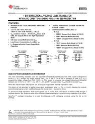
ABSOLUTE MAXIMUM RATINGS (T A = 25°C unless otherwise specified)<br />
Parameter Device Symbol Value Units<br />
TOTAL DEVICE<br />
Storage Temperature All T STG -55 to +150 °C<br />
Operating Temperature All T OPR -55 to +100 °C<br />
Lead Solder Temperature All T SOL 260 for 10 sec °C<br />
Total Device Power Dissipation @ T A = 25°C<br />
Derate above 25°C<br />
EMITTER<br />
All P D<br />
250 mW<br />
3.3 (non-M) 2.94 (-M) mW/°C<br />
DC/Average Forward Input Current All I F 100 (non-M), 60 (-M) mA<br />
<strong>TIL111</strong>/<strong>TIL111</strong>-M<br />
3<br />
Reverse Input Voltage<br />
V R V<br />
<strong>MOC8100</strong>-M/<strong>TIL117</strong>-M 6<br />
Forward Current - Peak (300µs, 2% Duty Cycle) All I F (pk) 3 A<br />
LED Power Dissipation @ T A = 25 °C<br />
Derate above 25°C<br />
DETECTOR<br />
All P D<br />
150 (non-M), 120 (-M) mW<br />
2.0 (non-M), 1.41 (-M) mW/°C<br />
Collector-Emitter Voltage All V CEO 30 V<br />
Collector-Base Voltage All V CBO 70 V<br />
Emitter-Collector Voltage <strong>TIL111</strong>-M/<strong>TIL117</strong>-M V ECO 7<br />
Emitter-Base Voltage All V EBO 7<br />
V<br />
Detector Power Dissipation @ T A = 25 °C<br />
Derate above 25°C<br />
All P D<br />
150 mW<br />
2.0 (non-M), 1.76 (-M) mW/°C<br />
© 2003 Fairchild Semiconductor Corporation<br />
Page 2 of 14<br />
6/30/03
GENERAL PURPOSE 6-PIN<br />
PHOTOTRANSISTOR OPTOCOUPLERS<br />
<strong>TIL111</strong> <strong>TIL111</strong>-M <strong>TIL117</strong>-M <strong>MOC8100</strong>-M<br />
ELECTRICAL CHARACTERISTICS (T A = 25°C unless otherwise specified)<br />
INDIVIDUAL COMPONENT CHARACTERISTICS<br />
1.2 1.4<br />
Parameter Test Conditions Device Symbol Min Typ* Max Unit<br />
EMITTER<br />
Input Forward Voltage (I F = 16 mA) (T A = 25°C) <strong>TIL111</strong>/<strong>TIL111</strong>-M<br />
(I F = 10 mA; for (T A = 0-70°C)<br />
1.2 1.4<br />
<strong>MOC8100</strong>-M)<br />
V<br />
(T<br />
<strong>MOC8100</strong>-M/ F<br />
A = -55°C) 1.32<br />
(I F = 16 mA; for<br />
<strong>TIL117</strong>-M<br />
V<br />
<strong>TIL117</strong>-M) (T A = +100°C) 1.10<br />
Reverse Leakage Current<br />
DETECTOR<br />
(V R = 3.0 V)<br />
<strong>TIL111</strong>/<strong>TIL111</strong>-M/<br />
<strong>TIL117</strong>-M I R<br />
0.001 10 µA<br />
(V R = 6.0V) <strong>MOC8100</strong>-M 0.001 10 µA<br />
Collector-Emitter Breakdown Voltage (I C = 1.0 mA, I F = 0) All BV CEO 30 100 V<br />
Collector-Base Breakdown Voltage (I C = 10 µA, I F = 0) All BV CBO 70 120 V<br />
Emitter-Base Breakdown Voltage (I E = 10 µA, I F = 0) All BV EBO 7 10 V<br />
Emitter-Collector Breakdown Voltage (I F = 100µA, I F = 0)<br />
Collector-Emitter Dark Current<br />
<strong>TIL111</strong>-M<br />
<strong>TIL117</strong>-M<br />
BV ECO 7 10 V<br />
(V CE = 10 V, I F = 0)<br />
<strong>TIL111</strong>/<strong>TIL111</strong>-M/<br />
<strong>TIL117</strong>-M<br />
I CEO 1 50 nA<br />
(V CE = 5V, T A = 25°C) <strong>MOC8100</strong>-M I CEO 0.5 25 nA<br />
(V CE = 30 V, I F = 0, T A = 70°C)<br />
<strong>TIL117</strong>-M/<br />
<strong>MOC8100</strong>-M<br />
I CEO 0.2 50 µA<br />
<strong>TIL111</strong>/<strong>TIL111</strong>-M/<br />
(V CB = 10 V)<br />
I<br />
Collector-Base Dark Current<br />
<strong>TIL117</strong>-M CBO 20 nA<br />
(V CB = 5 V) <strong>MOC8100</strong>-M I CBO 10 nA<br />
Capacitance (V CE = 0 V, f = 1 MHz) All C CE 8 pF<br />
ISOLATION CHARACTERISTICS<br />
Characteristic Test Conditions Symbol Min Typ* Max Units<br />
(Non ‘-M’, Black Package) (f = 60 Hz, t = 1 min)<br />
5300 Vac(rms)<br />
Input-Output Isolation Voltage<br />
V ISO<br />
(‘-M’, White Package) (f = 60 Hz, t = 1 sec) 7500 Vac(pk)<br />
Isolation Resistance (V I-O = 500 VDC) R ISO 10 11 Ω<br />
Isolation Capacitance (V I-O = 0, f = 1 MHz) C ISO 2 pF<br />
Note<br />
* Typical values at T A = 25°C unless otherwise noted<br />
© 2003 Fairchild Semiconductor Corporation<br />
Page 3 of 14<br />
6/30/03
GENERAL PURPOSE 6-PIN<br />
PHOTOTRANSISTOR OPTOCOUPLERS<br />
<strong>TIL111</strong> <strong>TIL111</strong>-M <strong>TIL117</strong>-M <strong>MOC8100</strong>-M<br />
TRANSFER CHARACTERISTICS (T A = 25°C Unless otherwise specified.)<br />
DC Characteristic Test Conditions Symbol Device Min Typ* Max Unit<br />
Current Transfer Ratio,<br />
Collector to Emitter<br />
On-State Collector Current<br />
(Phototransistor Operation)<br />
On-State Collector Current<br />
(Photodiode Operation)<br />
Collector-Emitter Saturation<br />
Voltage<br />
AC Characteristic<br />
* Typical values at T A = 25°C<br />
(I F = 10 mA, V CE = 10 V)<br />
<strong>TIL117</strong>-M 50 %<br />
(I F = 1 mA, V CE = 5 V)<br />
CTR CE 50<br />
<strong>MOC8100</strong>-M<br />
%<br />
(I F = 1 mA, V CE = 5 V, T A = 0 to +70°C) 30<br />
(I F = 16 mA, V CE = 0.4 V)<br />
2 mA<br />
<strong>TIL111</strong><br />
I C(ON) <strong>TIL111</strong>-M<br />
(I F = 16 mA, V CB = 0.4V) 7 µA<br />
(I C = 500 µA, I F = 10 mA)<br />
<strong>TIL117</strong>-M 0.4<br />
<strong>TIL111</strong><br />
(I C = 2 mA, I F = 16 mA) V CE (SAT) 0.4<br />
<strong>TIL111</strong>-M<br />
(I C = 100 µA, I F = 1 mA) <strong>MOC8100</strong>-M 0.5<br />
Turn-On Time<br />
Turn-Off Time<br />
<strong>MOC8100</strong>-M 20<br />
T ON<br />
<strong>TIL117</strong>-M 10<br />
(I C = 2 mA, V CC = 10 V,<br />
<strong>MOC8100</strong>-M 20<br />
T<br />
R L = 100Ω) (Fig. 20)<br />
OFF<br />
<strong>TIL117</strong>-M 10<br />
Rise Time t r <strong>MOC8100</strong>-M<br />
2<br />
Fall Time t f<br />
<strong>TIL117</strong>-M<br />
2<br />
Rise Time<br />
(Phototransistor Operation) (I C(ON) = 2 mA, V CC = 10 V,<br />
Fall Time<br />
R L = 100Ω) (Fig. 20)<br />
(Phototransistor Operation)<br />
t r<br />
t f<br />
<strong>TIL111</strong><br />
<strong>TIL111</strong>-M<br />
V<br />
µs<br />
µs<br />
µs<br />
10 µs<br />
© 2003 Fairchild Semiconductor Corporation<br />
Page 4 of 14<br />
6/30/03
NORMALIZED CTR<br />
NORMALIZED CTR<br />
NORMALIZED CTR<br />
NORMALIZED CTR<br />
GENERAL PURPOSE 6-PIN<br />
PHOTOTRANSISTOR OPTOCOUPLERS<br />
<strong>TIL111</strong> <strong>TIL111</strong>-M <strong>TIL117</strong>-M <strong>MOC8100</strong>-M<br />
TYPICAL PERFORMANCE CURVES<br />
Fig. 1 LED Forward Voltage vs. Forward Current<br />
(Black Package)<br />
Fig. 2 LED Forward Voltage vs. Forward Current<br />
(White Package)<br />
1.8<br />
1.8<br />
1.7<br />
1.7<br />
VF - FORWARD VOLTAGE (V)<br />
1.6<br />
1.5<br />
1.4<br />
1.3<br />
1.2<br />
T A = -55°C<br />
TA = 25°C<br />
VF - FORWARD VOLTAGE (V)<br />
1.6<br />
1.5<br />
1.4<br />
1.3<br />
1.2<br />
TA = -55°C<br />
T A = 25°C<br />
1.1<br />
TA = 100°C<br />
1.1<br />
T A = 100°C<br />
1.0<br />
1.0<br />
1 10 100<br />
1 10 100<br />
I F - LED FORWARD CURRENT (mA)<br />
I F - LED FORWARD CURRENT (mA)<br />
Fig.3 Normalized CTR vs. Forward Current<br />
(Black Package)<br />
Fig.4 Normalized CTR vs. Forward Current<br />
(White Package)<br />
1.4<br />
1.2<br />
VCE = 5.0V<br />
TA = 25°C<br />
Normalized to<br />
IF = 10 mA<br />
1.6<br />
1.4<br />
VCE = 5.0V<br />
TA = 25°C<br />
Normalized to<br />
IF = 10 mA<br />
1.0<br />
1.2<br />
1.0<br />
0.8<br />
0.8<br />
0.6<br />
0.6<br />
0.4<br />
0.4<br />
0.2<br />
0.2<br />
0.0<br />
0 5 10 15 20<br />
I F - FORWARD CURRENT (mA)<br />
0.0<br />
0 2 4 6 8 10 12 14 16 18 20<br />
I F - FORWARD CURRENT (mA)<br />
Fig. 5 Normalized CTR vs. Ambient Temperature<br />
(Black Package)<br />
Fig. 6 Normalized CTR vs. Ambient Temperature<br />
(White Package)<br />
1.6<br />
1.4<br />
1.4<br />
I F = 5 mA<br />
1.2<br />
I F = 5 mA<br />
1.2<br />
1.0<br />
IF = 10 mA<br />
IF = 10 mA<br />
1.0<br />
0.8<br />
0.8<br />
0.6<br />
I F = 20 mA<br />
0.6<br />
Normalized to<br />
IF = 10 mA<br />
TA = 25°C<br />
I F = 20 mA<br />
0.4<br />
Normalized to<br />
IF = 10 mA<br />
TA = 25°C<br />
0.4<br />
0.2<br />
-75 -50 -25 0 25 50 75 100 125<br />
T A - AMBIENT TEMPERATURE (°C)<br />
-60 -40 -20 0 20 40 60 80 100<br />
T A - AMBIENT TEMPERATURE (°C)<br />
© 2003 Fairchild Semiconductor Corporation<br />
Page 5 of 14<br />
6/30/03
GENERAL PURPOSE 6-PIN<br />
PHOTOTRANSISTOR OPTOCOUPLERS<br />
<strong>TIL111</strong> <strong>TIL111</strong>-M <strong>TIL117</strong>-M <strong>MOC8100</strong>-M<br />
NORMALIZED CTR ( CTRRBE / CTRRBE(OPEN))<br />
1.0<br />
0.9<br />
0.8<br />
0.7<br />
0.6<br />
0.5<br />
0.4<br />
0.3<br />
0.2<br />
0.1<br />
Fig. 7 CTR vs. RBE (Unsaturated)<br />
(Black Package)<br />
IF = 20 mA<br />
IF = 10 mA<br />
IF = 5 mA<br />
V CE= 5.0 V<br />
Fig. 8 CTR vs. RBE (Unsaturated)<br />
(White Package)<br />
0.0<br />
10 100 1000<br />
10 100 1000<br />
R BE- BASE RESISTANCE (kΩ) R BE- BASE RESISTANCE (kΩ)<br />
NORMALIZED CTR ( CTRRBE / CTRRBE(OPEN))<br />
1.0<br />
0.9<br />
0.8<br />
0.7<br />
0.6<br />
0.5<br />
0.4<br />
0.3<br />
0.2<br />
0.1<br />
0.0<br />
I F = 20 mA<br />
IF = 10 mA<br />
IF = 5 mA<br />
VCE= 5.0 V<br />
Fig. 9 CTR vs. RBE (Saturated)<br />
(Black Package)<br />
Fig. 10 CTR vs. RBE (Saturated)<br />
(White Package)<br />
1.0<br />
1.0<br />
NORMALIZED CTR ( CTRRBE / CTRRBE(OPEN))<br />
0.9<br />
0.8<br />
0.7<br />
0.6<br />
0.5<br />
0.4<br />
0.3<br />
0.2<br />
0.1<br />
IF = 20 mA<br />
I F = 10 mA<br />
IF = 5 mA<br />
VCE= 0.3 V<br />
NORMALIZED CTR ( CTRRBE / CTRRBE(OPEN))<br />
0.9<br />
0.8<br />
0.7<br />
0.6<br />
0.5<br />
0.4<br />
0.3<br />
0.2<br />
0.1<br />
I F = 20 mA<br />
IF = 10 mA<br />
IF = 5 mA<br />
V CE= 0.3 V<br />
0.0<br />
0.0<br />
10 100 1000<br />
10 100 1000<br />
R BE- BASE RESISTANCE (k Ω) R BE- BASE RESISTANCE (k Ω)<br />
Fig. 11 Collector-Emitter Saturation Voltage vs Collector Current<br />
(Black Package)<br />
Fig. 12 Collector-Emitter Saturation Voltage vs Collector Current<br />
(White Package)<br />
VCE (SAT) - COLLECTOR-EMITTER SATURATION VOLTAGE (V)<br />
100<br />
10<br />
1<br />
0.1<br />
0.01<br />
I F = 5 mA<br />
I F = 2.5 mA<br />
IF = 10 mA<br />
I C - COLLECTOR CURRENT (mA)<br />
IF = 20 mA<br />
TA = 25˚C<br />
0.001<br />
0.01 0.1 1 10<br />
VCE (SAT) - COLLECTOR-EMITTER SATURATION VOLTAGE (V)<br />
100<br />
10<br />
1<br />
0.1<br />
0.01<br />
TA = 25˚C<br />
I F = 5 mA<br />
I F = 2.5 mA<br />
I F = 10 mA<br />
I F = 20 mA<br />
0.001<br />
0.01 0.1 1 10<br />
I C - COLLECTOR CURRENT (mA)<br />
© 2003 Fairchild Semiconductor Corporation<br />
Page 6 of 14<br />
6/30/03
SWITCHING SPEED - (µs)<br />
SWITCHING SPEED - (µs)<br />
GENERAL PURPOSE 6-PIN<br />
PHOTOTRANSISTOR OPTOCOUPLERS<br />
<strong>TIL111</strong> <strong>TIL111</strong>-M <strong>TIL117</strong>-M <strong>MOC8100</strong>-M<br />
Fig. 13 Switching Speed vs. Load Resistor<br />
(Black Package)<br />
Fig. 14 Switching Speed vs. Load Resistor<br />
(White Package)<br />
1000<br />
1000<br />
I F = 10 mA<br />
V CC = 10 V<br />
TA = 25°C<br />
I F = 10 mA<br />
VCC = 10 V<br />
TA = 25°C<br />
100<br />
100<br />
10<br />
T off<br />
10<br />
Toff<br />
T f<br />
Ton<br />
Ton<br />
1<br />
Tr<br />
1<br />
T r<br />
0.1<br />
0.1<br />
0.1 1 10 100<br />
0.1 1 10 100<br />
R-LOAD RESISTOR (kΩ)<br />
R-LOAD RESISTOR (kΩ)<br />
5.0<br />
Fig. 15 Normalized t on vs. R BE<br />
(Black Package)<br />
5.0<br />
Fig. 16 Normalized t on vs. R BE<br />
(White Package)<br />
NORMALIZED ton - (ton(R BE) / ton(open))<br />
4.5<br />
4.0<br />
3.5<br />
3.0<br />
2.5<br />
2.0<br />
1.5<br />
VCC = 10 V<br />
IC = 2 mA<br />
RL = 100 Ω<br />
NORMALIZED ton - (ton(R BE) / ton(open))<br />
4.5<br />
4.0<br />
3.5<br />
3.0<br />
2.5<br />
2.0<br />
1.5<br />
1.0<br />
VCC = 10 V<br />
IC = 2 mA<br />
RL = 100 Ω<br />
T f<br />
0.1<br />
1.0<br />
0.5<br />
10 100 1000 10000 100000 10 100 1000 10000 100000<br />
R BE- BASE RESISTANCE (k Ω) R BE- BASE RESISTANCE (k Ω)<br />
Fig. 17 Normalized t off vs. R BE<br />
(Black Package)<br />
Fig. 18 Normalized t off vs. R BE<br />
(White Package)<br />
1.4<br />
1.4<br />
1.3<br />
1.3<br />
NORMALIZED toff - (toff(R BE) / toff(open))<br />
1.2<br />
1.1<br />
1.0<br />
0.9<br />
0.8<br />
0.7<br />
0.6<br />
0.5<br />
0.4<br />
0.3<br />
VCC = 10 V<br />
IC = 2 mA<br />
RL = 100 Ω<br />
NORMALIZED toff - (toff(R BE) / toff(open))<br />
1.2<br />
1.1<br />
1.0<br />
0.9<br />
0.8<br />
0.7<br />
0.6<br />
0.5<br />
0.4<br />
0.3<br />
VCC = 10 V<br />
IC = 2 mA<br />
RL = 100 Ω<br />
0.2<br />
0.2<br />
0.1<br />
10 100 1000 10000 100000<br />
R BE- BASE RESISTANCE (k Ω)<br />
10 100 1000 10000 100000<br />
R BE- BASE RESISTANCE (k Ω)<br />
© 2003 Fairchild Semiconductor Corporation<br />
Page 7 of 14<br />
6/30/03
I CEO - COLLECTOR -EMITTER DARK CURRENT (nA)<br />
GENERAL PURPOSE 6-PIN<br />
PHOTOTRANSISTOR OPTOCOUPLERS<br />
<strong>TIL111</strong> <strong>TIL111</strong>-M <strong>TIL117</strong>-M <strong>MOC8100</strong>-M<br />
Fig. 19 Dark Current vs. Ambient Temperature<br />
10000<br />
1000<br />
V CE = 10 V<br />
T A = 25°C<br />
100<br />
10<br />
1<br />
0.1<br />
0.01<br />
0.001<br />
0 20 40 60 80 100<br />
T A - AMBIENT TEMPERATURE (°C)<br />
TEST CIRCUIT<br />
WAVE FORMS<br />
I F<br />
V CC = 10V<br />
I C<br />
R L<br />
INPUT PULSE<br />
INPUT<br />
R BE<br />
OUTPUT<br />
10%<br />
90%<br />
t r<br />
t f<br />
OUTPUT PULSE<br />
Adjust I F to produce IC = 2 mA<br />
t on<br />
t off<br />
Figure 20. Switching Time Test Circuit and Waveforms<br />
© 2003 Fairchild Semiconductor Corporation<br />
Page 8 of 14<br />
6/30/03
GENERAL PURPOSE 6-PIN<br />
PHOTOTRANSISTOR OPTOCOUPLERS<br />
<strong>TIL111</strong> <strong>TIL111</strong>-M <strong>TIL117</strong>-M <strong>MOC8100</strong>-M<br />
White Package (-M Suffix)<br />
Package Dimensions (Through Hole)<br />
Package Dimensions (Surface Mount)<br />
0.350 (8.89)<br />
0.320 (8.13)<br />
0.350 (8.89)<br />
0.320 (8.13)<br />
Pin 1 ID<br />
PIN 1 ID<br />
0.260 (6.60)<br />
0.240 (6.10)<br />
0.260 (6.60)<br />
0.240 (6.10)<br />
0.390 (9.90)<br />
0.332 (8.43)<br />
SEATING PLANE<br />
0.070 (1.77)<br />
0.040 (1.02)<br />
0.200 (5.08)<br />
0.115 (2.93)<br />
0.014 (0.36)<br />
0.010 (0.25)<br />
0.320 (8.13)<br />
SEATING PLANE<br />
0.070 (1.77)<br />
0.040 (1.02)<br />
0.200 (5.08)<br />
0.115 (2.93)<br />
0.014 (0.36)<br />
0.010 (0.25)<br />
0.012 (0.30)<br />
0.008 (0.20)<br />
0.320 (8.13)<br />
0.100 (2.54)<br />
0.015 (0.38)<br />
0.020 (0.50)<br />
0.016 (0.41)<br />
0.100 (2.54)<br />
15°<br />
0.012 (0.30)<br />
0.025 (0.63)<br />
0.020 (0.51)<br />
0.020 (0.50)<br />
0.016 (0.41)<br />
0.100 [2.54]<br />
0.035 (0.88)<br />
0.006 (0.16)<br />
Package Dimensions (0.4” Lead Spacing)<br />
0.350 (8.89)<br />
0.320 (8.13)<br />
PIN 1 ID<br />
Recommended Pad Layout for<br />
Surface Mount Leadform<br />
0.070 (1.78)<br />
0.260 (6.60)<br />
0.240 (6.10)<br />
0.060 (1.52)<br />
SEATING PLANE<br />
0.070 (1.77)<br />
0.040 (1.02)<br />
0.200 (5.08)<br />
0.115 (2.93)<br />
0.014 (0.36)<br />
0.010 (0.25)<br />
0.425 (10.79)<br />
0.305 (7.75)<br />
0.100 (2.54)<br />
0.030 (0.76)<br />
0.100 (2.54)<br />
0.015 (0.38)<br />
0.020 (0.50)<br />
0.016 (0.41)<br />
0.100 [2.54]<br />
0.012 (0.30)<br />
0.008 (0.21)<br />
0.425 (10.80)<br />
0.400 (10.16)<br />
NOTE<br />
All dimensions are in inches (millimeters)<br />
© 2003 Fairchild Semiconductor Corporation<br />
Page 9 of 14<br />
6/30/03
GENERAL PURPOSE 6-PIN<br />
PHOTOTRANSISTOR OPTOCOUPLERS<br />
<strong>TIL111</strong> <strong>TIL111</strong>-M <strong>TIL117</strong>-M <strong>MOC8100</strong>-M<br />
Black Package (No -M Suffix)<br />
Package Dimensions (Through Hole)<br />
Package Dimensions (Surface Mount)<br />
PIN 1<br />
ID.<br />
0.350 (8.89)<br />
0.330 (8.38)<br />
0.270 (6.86)<br />
0.240 (6.10)<br />
3<br />
2<br />
1<br />
PIN 1<br />
ID.<br />
0.270 (6.86)<br />
0.240 (6.10)<br />
SEATING PLANE<br />
0.070 (1.78)<br />
0.045 (1.14)<br />
0.350 (8.89)<br />
0.330 (8.38)<br />
4<br />
5<br />
6<br />
0.070 (1.78)<br />
0.045 (1.14)<br />
0.300 (7.62)<br />
TYP<br />
0.200 (5.08)<br />
0.115 (2.92)<br />
0.200 (5.08)<br />
0.165 (4.18)<br />
0.016 (0.41)<br />
0.008 (0.20)<br />
0.154 (3.90)<br />
0.100 (2.54)<br />
0.022 (0.56)<br />
0.016 (0.41)<br />
0.100 (2.54)<br />
TYP<br />
0.020 (0.51)<br />
MIN<br />
0.016 (0.40)<br />
0.008 (0.20)<br />
0° to 15°<br />
0.300 (7.62)<br />
TYP<br />
0.022 (0.56)<br />
0.016 (0.41)<br />
0.020 (0.51)<br />
MIN<br />
0.100 (2.54)<br />
TYP<br />
Lead Coplanarity : 0.004 (0.10) MAX<br />
0.016 (0.40) MIN<br />
0.315 (8.00)<br />
MIN<br />
0.405 (10.30)<br />
MAX<br />
Package Dimensions (0.4” Lead Spacing)<br />
Recommended Pad Layout for<br />
Surface Mount Leadform<br />
PIN 1 ID<br />
0.270 (6.86)<br />
0.240 (6.10)<br />
0.070 (1.78)<br />
0.060 (1.52)<br />
SEATING PLANE<br />
0.200 (5.08)<br />
0.135 (3.43)<br />
0.350 (8.89)<br />
0.330 (8.38)<br />
0.070 (1.78)<br />
0.045 (1.14)<br />
0.415 (10.54)<br />
0.295 (7.49)<br />
0.100 (2.54)<br />
0.030 (0.76)<br />
0.154 (3.90)<br />
0.100 (2.54)<br />
0.004 (0.10)<br />
MIN<br />
0.016 (0.40)<br />
0.008 (0.20)<br />
0.022 (0.56)<br />
0.016 (0.41)<br />
0.100 (2.54) TYP<br />
0.400 (10.16)<br />
TYP<br />
0° to 15°<br />
NOTE<br />
All dimensions are in inches (millimeters)<br />
© 2003 Fairchild Semiconductor Corporation<br />
Page 10 of 14<br />
6/30/03
GENERAL PURPOSE 6-PIN<br />
PHOTOTRANSISTOR OPTOCOUPLERS<br />
<strong>TIL111</strong> <strong>TIL111</strong>-M <strong>TIL117</strong>-M <strong>MOC8100</strong>-M<br />
ORDERING INFORMATION<br />
Order Entry Identifier<br />
Black Package (No Suffix) White Package (-M Suffix) Option<br />
.S S Surface Mount Lead Bend<br />
.SD SR2 Surface Mount; Tape and reel<br />
.W T 0.4" Lead Spacing<br />
.300 V VDE 0884<br />
.300W TV VDE 0884, 0.4" Lead Spacing<br />
.3S SV VDE 0884, Surface Mount<br />
.3SD SR2V VDE 0884, Surface Mount, Tape & Reel<br />
MARKING INFORMATION<br />
1<br />
1<br />
<strong>TIL111</strong><br />
2<br />
<strong>TIL111</strong><br />
2<br />
V XX YY K<br />
6<br />
V<br />
X YY Q<br />
6<br />
3 4 5<br />
Black Package, No Suffix<br />
3 4 5<br />
White Package, -M Suffix<br />
Definitions<br />
1 Fairchild logo<br />
2 Device number<br />
VDE mark (Note: Only appears on parts ordered with VDE<br />
3<br />
option – See order entry table)<br />
One or two digit year code<br />
4 • Two digits for black package parts, e.g., ‘03’<br />
• One digit for white package parts, e.g., ‘3’<br />
5 Two digit work week ranging from ‘01’ to ‘53’<br />
6 Assembly package code<br />
*Note – Parts built in the white package (M suffix) that do not have the ‘V’ option (see<br />
definition 3 above) that are marked with date code ‘325’ or earlier are marked in the<br />
portrait format.<br />
© 2003 Fairchild Semiconductor Corporation<br />
Page 11 of 14<br />
6/30/03
GENERAL PURPOSE 6-PIN<br />
PHOTOTRANSISTOR OPTOCOUPLERS<br />
<strong>TIL111</strong> <strong>TIL111</strong>-M <strong>TIL117</strong>-M <strong>MOC8100</strong>-M<br />
Carrier Tape Specifications (Black Package, No Suffix)<br />
4.85 ± 0.20<br />
0.30 ± 0.05<br />
4.0 ± 0.1<br />
12.0 ± 0.1<br />
4.0 ± 0.1<br />
Ø1.55 ± 0.05<br />
1.75 ± 0.10<br />
13.2 ± 0.2<br />
7.5 ± 0.1<br />
16.0 ± 0.3<br />
9.55 ± 0.20<br />
0.1 MAX 10.30 ± 0.20<br />
Ø1.6 ± 0.1<br />
User Direction of Feed<br />
Carrier Tape Specifications (White Package, -M Suffix)<br />
4.5 ± 0.20<br />
0.30 ± 0.05<br />
4.0 ± 0.1<br />
12.0 ± 0.1<br />
2.0 ± 0.05<br />
Ø1.5 MIN<br />
1.75 ± 0.10<br />
21.0 ± 0.1<br />
11.5 ± 1.0<br />
24.0 ± 0.3<br />
9.1 ± 0.20<br />
0.1 MAX 10.1 ± 0.20<br />
Ø1.5 ± 0.1/-0<br />
User Direction of Feed<br />
© 2003 Fairchild Semiconductor Corporation<br />
Page 12 of 14<br />
6/30/03
GENERAL PURPOSE 6-PIN<br />
PHOTOTRANSISTOR OPTOCOUPLERS<br />
<strong>TIL111</strong> <strong>TIL111</strong>-M <strong>TIL117</strong>-M <strong>MOC8100</strong>-M<br />
Reflow Profile (White Package, -M Suffix)<br />
Temperature (°C)<br />
300<br />
250<br />
200<br />
150<br />
100<br />
50<br />
0<br />
0<br />
245°C peak<br />
230°C, 10–30 s<br />
Time above 183°C, 120–180 sec<br />
Ramp up = 2–10°C/sec • Peak reflow temperature: 245°C (package surface temperature)<br />
• Time of temperature higher than 183°C for 120–180 seconds<br />
• One time soldering reflow is recommended<br />
0.5 1 1.5 2 2.5 3 3.5 4 4.5<br />
Time (Minute)<br />
Reflow Profile (Black Package, No Suffix)<br />
Temperature (°C)<br />
300<br />
250<br />
200<br />
150<br />
100<br />
50<br />
215°C, 10–30 s<br />
225 C peak<br />
Time above 183°C, 60–150 sec<br />
Ramp up = 3C/sec<br />
• Peak reflow temperature: 225°C (package surface temperature)<br />
• Time of temperature higher than 183°C for 60–150 seconds<br />
• One time soldering reflow is recommended<br />
0<br />
0<br />
0.5 1 1.5 2 2.5 3 3.5 4 4.5<br />
Time (Minute)<br />
© 2003 Fairchild Semiconductor Corporation<br />
Page 13 of 14<br />
6/30/03
GENERAL PURPOSE 6-PIN<br />
PHOTOTRANSISTOR OPTOCOUPLERS<br />
<strong>TIL111</strong> <strong>TIL111</strong>-M <strong>TIL117</strong>-M <strong>MOC8100</strong>-M<br />
DISCLAIMER<br />
FAIRCHILD SEMICONDUCTOR RESERVES THE RIGHT TO MAKE CHANGES WITHOUT FURTHER NOTICE TO<br />
ANY PRODUCTS HEREIN TO IMPROVE RELIABILITY, FUNCTION OR DESIGN. FAIRCHILD DOES NOT ASSUME<br />
ANY LIABILITY ARISING OUT OF THE APPLICATION OR USE OF ANY PRODUCT OR CIRCUIT DESCRIBED HEREIN;<br />
NEITHER DOES IT CONVEY ANY LICENSE UNDER ITS PATENT RIGHTS, NOR THE RIGHTS OF OTHERS.<br />
LIFE SUPPORT POLICY<br />
FAIRCHILD’S PRODUCTS ARE NOT AUTHORIZED FOR USE AS CRITICAL COMPONENTS IN LIFE SUPPORT DEVICES<br />
OR SYSTEMS WITHOUT THE EXPRESS WRITTEN APPROVAL OF THE PRESIDENT OF FAIRCHILD SEMICONDUCTOR<br />
CORPORATION. As used herein:<br />
1. Life support devices or systems are devices or systems<br />
which, (a) are intended for surgical implant into the body, or<br />
(b) support or sustain life, and (c) whose failure to perform<br />
when properly used in accordance with instructions for use<br />
provided in the labeling, can be reasonably expected to<br />
result in a significant injury of the user.<br />
2. A critical component in any component of a life support<br />
device or system whose failure to perform can be<br />
reasonably expected to cause the failure of the life support<br />
device or system, or to affect its safety or effectiveness.<br />
© 2003 Fairchild Semiconductor Corporation<br />
Page 14 of 14<br />
6/30/03