CMOS Linear Applications
CMOS Linear Applications
CMOS Linear Applications

Create successful ePaper yourself
Turn your PDF publications into a flip-book with our unique Google optimized e-Paper software.
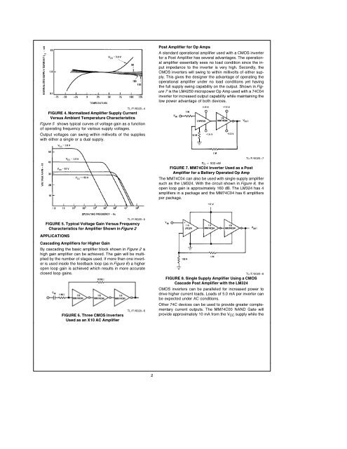
Post Amplifier for Op Amps<br />
A standard operational amplifier used with a <strong>CMOS</strong> inverter<br />
for a Post Amplifier has several advantages The operational<br />
amplifier essentially sees no load condition since the input<br />
impedance to the inverter is very high Secondly the<br />
<strong>CMOS</strong> inverters will swing to within millivolts of either supply<br />
This gives the designer the advantage of operating the<br />
operational amplifier under no load conditions yet having<br />
the full supply swing capability on the output Shown in Figure<br />
7 is the LM4250 micropower Op Amp used with a 74C04<br />
inverter for increased output capability while maintaining the<br />
low power advantage of both devices<br />
TLF6020–4<br />
FIGURE 4 Normalized Amplifier Supply Current<br />
Versus Ambient Temperature Characteristics<br />
Figure 5 shows typical curves of voltage gain as a function<br />
of operating frequency for various supply voltages<br />
Output voltages can swing within millivolts of the supplies<br />
with either a single or a dual supply<br />
TLF6020–7<br />
P D e 500 nW<br />
FIGURE 7 MM74C04 Inverter Used as a Post<br />
Amplifier for a Battery Operated Op Amp<br />
The MM74C04 can also be used with single supply amplifier<br />
such as the LM324 With the circuit shown in Figure 8 the<br />
open loop gain is approximately 160 dB The LM324 has 4<br />
amplifiers in a package and the MM74C04 has 6 amplifiers<br />
per package<br />
TLF6020–5<br />
FIGURE 5 Typical Voltage Gain Versus Frequency<br />
Characteristics for Amplifier Shown in Figure 2<br />
APPLICATIONS<br />
Cascading Amplifiers for Higher Gain<br />
By cascading the basic amplifier block shown in Figure 2 a<br />
high gain amplifier can be achieved The gain will be multiplied<br />
by the number of stages used If more than one inverter<br />
is used inside the feedback loop (as in Figure 6) a higher<br />
open loop gain is achieved which results in more accurate<br />
closed loop gains<br />
FIGURE 6 Three <strong>CMOS</strong> Inverters<br />
Used as an X10 AC Amplifier<br />
TLF6020–6<br />
TLF6020–8<br />
FIGURE 8 Single Supply Amplifier Using a <strong>CMOS</strong><br />
Cascade Post Amplifier with the LM324<br />
<strong>CMOS</strong> inverters can be paralleled for increased power to<br />
drive higher current loads Loads of 50 mA per inverter can<br />
be expected under AC conditions<br />
Other 74C devices can be used to provide greater complementary<br />
current outputs The MM74C00 NAND Gate will<br />
provide approximately 10 mA from the V CC supply while the<br />
2