Permeation Devices Technical Note
Permeation Devices Technical Note
Permeation Devices Technical Note

You also want an ePaper? Increase the reach of your titles
YUMPU automatically turns print PDFs into web optimized ePapers that Google loves.
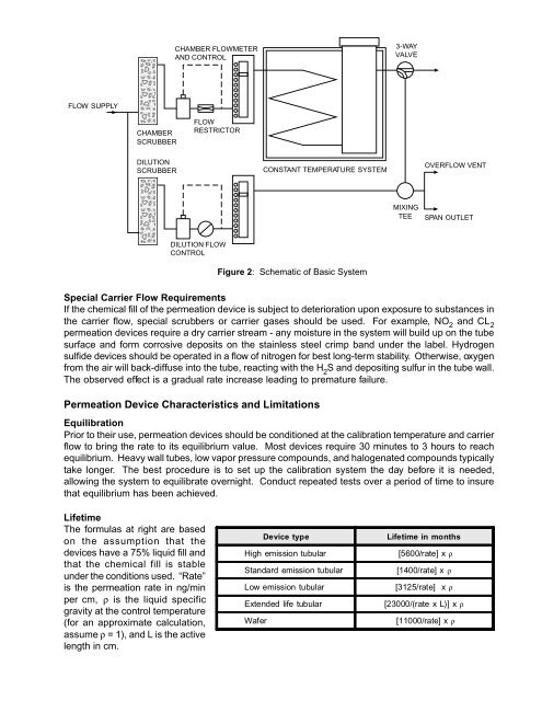
CHAMBER FLOWMETER<br />
3-WAY<br />
AND CONTROL<br />
VALVE<br />
FLOW SUPPLY<br />
FLOW<br />
CHAMBER RESTRICTOR<br />
SCRUBBER<br />
DILUTION<br />
OVERFLOW VENT<br />
SCRUBBER<br />
CONSTANT TEMPERATURE SYSTEM<br />
MIXING<br />
TEE SPAN OUTLET<br />
DILUTION FLOW<br />
CONTROL<br />
Figure 2: Schematic of Basic System<br />
Special Carrier Flow Requirements<br />
If the chemical fill of the permeation device is subject to deterioration upon exposure to substances in<br />
the carrier flow, special scrubbers or carrier gases should be used. For example, NO 2<br />
and CL 2<br />
permeation devices require a dry carrier stream - any moisture in the system will build up on the tube<br />
surface and form corrosive deposits on the stainless steel crimp band under the label. Hydrogen<br />
sulfide devices should be operated in a flow of nitrogen for best long-term stability. Otherwise, oxygen<br />
from the air will back-diffuse into the tube, reacting with the H 2<br />
S and depositing sulfur in the tube wall.<br />
The observed effect is a gradual rate increase leading to premature failure.<br />
<br />
<strong>Permeation</strong> Device Characteristics and Limitations<br />
Equilibration<br />
Prior to their use, permeation devices should be conditioned at the calibration temperature and carrier<br />
flow to bring the rate to its equilibrium value. Most devices require 30 minutes to 3 hours to reach<br />
equilibrium. Heavy wall tubes, low vapor pressure compounds, and halogenated compounds typically<br />
take longer. The best procedure is to set up the calibration system the day before it is needed,<br />
allowing the system to equilibrate overnight. Conduct repeated tests over a period of time to insure<br />
that equilibrium has been achieved.<br />
Lifetime<br />
The formulas at right are based<br />
on the assumption that the<br />
devices have a 75% liquid fill and<br />
that the chemical fill is stable<br />
under the conditions used. “Rate”<br />
is the permeation rate in ng/min<br />
per cm, ρ is the liquid specific<br />
gravity at the control temperature<br />
(for an approximate calculation,<br />
assume ρ = 1), and L is the active<br />
length in cm.<br />
Device type<br />
Lifetime in months<br />
High emission tubular [5600/rate] x ρ<br />
Standard emission tubular<br />
Low emission tubular<br />
Extended life tubular<br />
[1400/rate] x ρ<br />
[3125/rate] x ρ<br />
[23000/(rate x L)] x ρ<br />
Wafer [11000/rate] x ρ