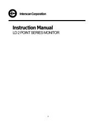
Instruction Manual - Interscan Corporation
Instruction Manual - Interscan Corporation
Instruction Manual - Interscan Corporation

You also want an ePaper? Increase the reach of your titles
YUMPU automatically turns print PDFs into web optimized ePapers that Google loves.
<strong>Interscan</strong> <strong>Corporation</strong>.<br />
<strong>Instruction</strong> <strong>Manual</strong><br />
LD Continuous Monitoring System<br />
I
Table of Contents<br />
Introduction 1<br />
1.1 Component Check .................................................................. 1<br />
1.2 System Description ............................................................... 1<br />
1.3 Instrument Configuration ....................................................... 2<br />
Installation 3<br />
2.1 Wall Mounting ........................................................................ 3<br />
2.2 Plumbing The System ........................................................... 4<br />
2.2.1 Enclosure Fittings and Connections ........................ 4<br />
2.2.2 Balston Coalescer Filter (Optional)........................ 5<br />
2.3 Electrical Connections ........................................................... 6<br />
2.3.1 AC Line Cord ......................................................... 6<br />
2.3.2 Analog Voltage Output............................................ 6<br />
2.3.3 4-20 mA Current Output ......................................... 6<br />
2.3.4 Alarm Relay Contacts ............................................. 6<br />
2.4 Component Installation / Setup.......................................... 9<br />
2.4.1 Beacon-Ray Light or Strobe Light (Optional) ......... 9<br />
2.4.2 Vibratory Horn (Optional) ....................................... 9<br />
2.4.3 Sonalert Horn (Optional) ........................................ 9<br />
2.4.4 Power Off Alarm (Optional) .................................... 9<br />
Quick Start – Basic Functions and Features 11<br />
3.1 Front Panel Controls and Indicators .................................... 11<br />
3.2 Other Components ............................................................. 13<br />
3.2.1 Gas Sensor ............................................................ 13<br />
3.2.2 Sample Pump ........................................................ 13<br />
3.2.3 Visual Alarm (Optional).......................................... 14<br />
3.2.4 Audible Alarm (Optional)........................................ 14<br />
3.2.5 158LD Interference Scrubber (optional) ................ 14<br />
3.2.6 Enclosure Heater (Optional) ................................ 14<br />
3.3 Initial Start-up ...................................................................... 14<br />
3.4 Zeroing The Instrument ....................................................... 15<br />
3.5 Sampling .............................................................................. 15<br />
Advanced System Functions 16<br />
II
4.1 Programming Alarm Setpoints (Optional Feature) .............. 16<br />
4.1.1 Checking Alarm Set-Points ................................. 16<br />
4.1.2 Changing Alarm Setpoints .................................... 17<br />
4.2 Filter Clog Indication (Optional Feature) ............................ 17<br />
4.3 Zero Procedure ................................................................... 18<br />
4.4 Auto Zero (Optional)............................................................ 18<br />
4.4.1 Auto Zero Function .............................................. 18<br />
4.4.2 Zero Fault Indication ............................................. 19<br />
4.5 Sensor Protection Circuit (Optional Feature) ...................... 19<br />
4.6 Custom Features ................................................................. 20<br />
Sensor Calibration 21<br />
5.1 Introduction .......................................................................... 21<br />
5.2 Calibration Gas Standards............................................... 22<br />
5.2.1 Gas Blends In Cylinders ....................................... 22<br />
5.2.2 Permeation Devices .............................................. 22<br />
5.2.3 Cal Gas PPM Concentrations ............................... 22<br />
5.3 Sample Bag Gas Delivery ................................................ 23<br />
5.4 Calibration Procedure .......................................................... 23<br />
5.5 Calibration Procedure For Monitors With Dilution Systems . 24<br />
5.6 Electronic Calibration Service (ECS) ................................... 24<br />
Maintenance 26<br />
6.1 Inlet Particulate Filter ........................................................... 26<br />
6.2 Sensor Maintenance ........................................................... 27<br />
6.2.1 Sensor Weight ...................................................... 27<br />
6.2.2 Sensor Removal ................................................... 27<br />
6.2.3 Sensor Refilling Procedure ................................... 28<br />
6.3 Zero Air Filter (Optional)...................................................... 28<br />
6.4 Interference Scrubber (optional) .......................................... 29<br />
Troubleshooting 30<br />
Warranty 32<br />
Return Authorization 33<br />
Parts List 32<br />
III
Section<br />
1<br />
___________________________________________________________________________________________<br />
Introduction<br />
1.1 Component Check<br />
Check the contents list in each shipping container used to ship your monitor to ensure that all<br />
system accessories on the list(s) are included. Set all accessories aside until directed to install<br />
them later in the manual.<br />
1.2 System Description<br />
The <strong>Interscan</strong> LD Monitor consists of the <strong>Interscan</strong> gas sensor, sample draw pneumatics (where<br />
applicable), Digital meter/controller, and various alarm output devices.<br />
In basic operation sample air is drawn through the sensor, via a diaphragm sample pump and<br />
related pneumatics. The sensor’s electrical output is sent via the sensor circuit board to the digital<br />
panel meter which processes the sensor outputs and produces a digital readout in PPM (parts per<br />
million). The maximum readout will depend on the range ordered but will usually be 50.0 ppm for<br />
Ethylene Oxide monitors and 199.9 ppm or 19.99 ppm for all other gases. See section 1.3 for<br />
special range setup info if applicable.<br />
When ordered accordingly, the meter/controller also compares the current gas level to preset<br />
alarm levels and activates alarm indicators and/or relay contacts when gas levels exceed these<br />
user set levels, in addition to outputting a 4-20 mA analog signal in proportion to the full scale<br />
range of the system. A 0-1V analog output signal is standard on all LD monitors.<br />
ALL INTERSCAN MONITORS ARE CALIBRATED AT THE FACTORY PRIOR TO SHIPMENT.<br />
Unless the CAL control is inadvertently changed, no calibration is required until the unit has seen<br />
considerable use.<br />
1
1.3 Instrument Configuration<br />
If your monitor contains special custom features, the operational details of those<br />
features are shown below:<br />
GAS – Hydrazine<br />
FULL SCALE RANGE – 1000 ppm (Diluted Sample – D Factor = 50)<br />
OPTIONAL FEATURES INCLUDED<br />
AUTO ZERO – See section 4.4<br />
POWER OFF ALARM RELAY CONTACTS – See section 2.4.4<br />
DILUTION SYSTEM – See dedicated documentation.<br />
CUSTOM FEATURES<br />
NONE<br />
2
Section<br />
2<br />
___________________________________________________________________________________________<br />
Installation<br />
2.1 Wall Mounting<br />
The <strong>Interscan</strong> LD Monitoring System is housed in a NEMA 4X 16”W X 14”H X 8”D fiberglass<br />
enclosure. The enclosure is configured for wall mounting. The outer door is hinged on the bottom.<br />
For optimum access, enough room should be allowed to fully open the outer door. Secure the<br />
enclosure to the wall using 5/16 inch (7.937 mm) steel bolts. See figures 1-1 and 1-2 below for<br />
dimensional detail (only the furthest extruding exterior components are shown. Custom or special<br />
order features may not be pictured).<br />
3
2.2 Plumbing The System<br />
2.2.1 ENCLOSURE FITTINGS AND CONNECTIONS<br />
Sample air is drawn into and exhausted from the system via as series of pneumatic fittings located<br />
on the right side of the monitor enclosure. The locations, and purposes of the various fittings are<br />
detailed below.<br />
INLET<br />
Located on the upper right side of unit enclosure. Either a<br />
particulate filter or a bulkhead fitting through which sample air<br />
is drawn into the gas sensor. (See section 2.2.2 below).<br />
EXHAUST<br />
Located just below the inlet filter. A ¼” “push-in” style bulkhead<br />
fitting. This should be connected to an exhaust vent or<br />
manifold. Connect to this fitting by pushing tubing into the<br />
opening as far as possible and then gently pulling back on the<br />
tubing to ensure a tight fit.<br />
4
ZERO AIR<br />
Optional Feature - Located on the lower right side of unit<br />
enclosure.. A charcoal filter attached to a bulkhead fitting<br />
through which zero air sample is drawn during Auto Zero<br />
cycles. No connection is necessary.<br />
2.2.2 BALSTON COALESCER FILTER (OPTIONAL)<br />
Units ordered with a Balston Coalescer Filter will be shipped with the filter unattached to the unit.<br />
The standard Millipore filter housing shown in Fig 1.2 will be replaced by an inlet bulkhead fitting to<br />
which the Balston filter will connect according to figure 2-1 below. The open port of the Balston<br />
housing screws on to the male threads of the fitting on the upper right side of the enclosure.<br />
Should the Balston housing ever need to be removed from the unit, unscrew the filter from the<br />
fitting in a counter-clockwise direction and reattach by screwing the filter onto the fitting in a<br />
clockwise direction.<br />
5
2.3 Electrical Connections<br />
2.3.1 AC LINE CORD<br />
Located along the left side of the unit enclosure. Plug the line cord into any standard wall socket. If<br />
no line cord is present, refer to section 1.3 for special instructions.<br />
2.3.2 ANALOG VOLTAGE OUTPUT<br />
An analog voltage output signal (usually 0-1V at full scale) is provided, calibrated for 0 V when the<br />
meter display reads 0.0 ppm and 1 V when the meter reads full scale (see section 1.3). This<br />
output can be accessed at the RELAY CONTACT AND ANALOG OUTPUT BOARD which is<br />
located inside the unit on the left edge of the unit chassis. To access this board, open the unit<br />
enclosure, unscrew the 2 panel screws on the left side front panel and drop the panel. Loosen the<br />
2 screws securing the blue Alarm Board cover and slide the cover to the right, exposing the output<br />
terminals. All output designations are clearly marked on the board as shown in Figure 2-1 below<br />
for output terminal designations.<br />
2.3.3 4-20 MA CURRENT OUTPUT<br />
An analog 4-20 mA current loop output signal is provided which is calibrated for 4 mA when the<br />
meter display reads 0.0 ppm and 20 mA when the meter output reads full scale (see section 1.3).<br />
This output when provided can also be accessed at the RELAY CONTACT AND ANALOG<br />
OUTPUT BOARD as described in section 2.3.2 above. See Figure 2-1 below for output terminal<br />
designations.<br />
2.3.4 ALARM RELAY CONTACTS<br />
Form C Alarm relay contacts are provided and are also located at the RELAY CONTACT AND<br />
ANALOG OUTPUT BOARD as described in section 2.3.2 above. See Figure 2-1 below for output<br />
terminal designations in standard a configuration. A detailed verbal description of user output<br />
connections for the possible alarm output options is shown in tables 2-1 thru 2-3. The relay<br />
contacts are rated at 6 amps/120VAC, 6 amps/24VDC and 3 amps/240VAC.<br />
6
ALARM 1 OUTPUT<br />
ALARM 1 COMMON<br />
ALARM 1 NORMALLY OPEN<br />
ALARM 1 NORMALLY CLOSED<br />
TERMINATION<br />
1-C<br />
1-NO<br />
1-NC<br />
ALARM 2 OUTPUT<br />
ALARM 1 COMMON<br />
ALARM 1 NORMALLY OPEN<br />
ALARM 1 NORMALLY CLOSED<br />
TERMINATION<br />
2-C<br />
2-NO<br />
2-NC<br />
TABLE 2-1<br />
(Unwired relay contact outputs – Standard LD configuration)<br />
ALARM 1 OUTPUT<br />
24 VDC + OUTPUT<br />
24 VDC COMMON<br />
TERMINATION<br />
RELAY BOARD 1-NO<br />
TB1-1<br />
ALARM 2 OUTPUT<br />
24 VDC + OUTPUT<br />
24 VDC COMMON<br />
TERMINATION<br />
RELAY BOARD 2-NO<br />
TB1-1<br />
TABLE 2-2<br />
(DC wired relay contact outputs – LDXX-DC configuration)<br />
ALARM 1 OUTPUT<br />
24 VDC + OUTPUT<br />
24 VDC COMMON<br />
ACH OUTPUT<br />
ACN OUTPUT<br />
TERMINATION<br />
RELAY BOARD 1-NO<br />
TB1-1<br />
TB1-6 (Green Wire)<br />
TB1-5 (White Wire)<br />
ALARM 2 OUTPUT<br />
24 VDC + OUTPUT<br />
24 VDC COMMON<br />
ACH OUTPUT<br />
ACN OUTPUT<br />
TERMINATION<br />
RELAY BOARD 2-NO<br />
TB1-1<br />
TB1-3 (Green Stripe Wire)<br />
TB1-5 (White Wire)<br />
TABLE 2-3<br />
(DC & AC wired relay contact outputs – LDXX-AC/DC configuration)<br />
8
2.4 Component Installation / Setup<br />
The following section details installation and setup for optional features that will only be present if<br />
ordered for your monitor.<br />
2.4.1 BEACON-RAY LIGHT OR STROBE LIGHT (OPTIONAL)<br />
The optional Beacon-ray light or strobe light mounts to the left side conduit hub on the top of the<br />
enclosure. Feed the light's wires through the hub and thread the light into the hub and tighten.<br />
Connect the two twisted white wires (for beacon–ray light) or black wires (for strobe light) to the<br />
same colored mating pair inside the unit. Unless ordered otherwise, mounted light devices will<br />
activate when the LO ALARM (Alarm 1) level is exceeded.<br />
2.4.2 VIBRATORY HORN (OPTIONAL)<br />
The optional vibratory horn mounts to the right side conduit hub on the top of the enclosure. Feed<br />
the horn's wires through the hub and thread the horn into the hub and tighten. Connect the two<br />
twisted black wires from the horn to the same colored mating pair inside the unit. Unless ordered<br />
otherwise, mounted horn devices will activate when the HI ALARM (Alarm 2) level is exceeded.<br />
See section for more on alarms and alarm levels.<br />
2.4.3 SONALERT HORN (OPTIONAL)<br />
The optional Sonalert horn is installed by INTERSCAN prior to shipping and requires no additional<br />
adjustments upon receipt. It is a black plastic disk mounted on the right side of the top of the<br />
monitor. Unless ordered otherwise, mounted horn devices will activate when the HI ALARM<br />
(Alarm 2) level is exceeded. See section for more on alarms and alarm levels.<br />
2.4.4 POWER OFF ALARM (OPTIONAL)<br />
Units equipped with a POWER OFF ALARM feature will contain one or both of a set of relay<br />
contacts (see table below for terminal locations if provided), and/or an audible alarm that will be<br />
activated whenever power to the unit is lost. (See section 1.3 for exact configuration of your unit).<br />
The audible alarm includes an inhibit switch on the front panel labeled P.O. ALARM / OFF. The<br />
9
monitor is shipped with this switch in the OFF position. After AC power has been connected, set<br />
this switch to P.O. ALARM. The audible alarm is powered by a 9 volt alkaline battery. The alarm<br />
should be checked every few months to verify the battery condition supplies an adequate alarm.<br />
POWER OFF RELAY CONTACTS<br />
P.O. ALARM OUTPUT**<br />
COMMON<br />
NORMALLY OPEN<br />
NORMALLY CLOSED<br />
TERMINATION<br />
RELAY BOARD 5-C<br />
RELAY BOARD 5-NO<br />
RELAY BOARD 5-NC<br />
**NOTE: Power Off relay is energized when power is ON. For a contact closure when power is<br />
lost, use the NORMALLY CLOSED contact.<br />
10
Section<br />
3<br />
___________________________________________________________________________________________<br />
Quick Start – Basic Functions and Features<br />
This section gives a brief overview of the system’s most basic functions and components. A full reading<br />
of the manual is recommended for a thorough understanding of all unit functions.<br />
3.1 Front Panel Controls and Indicators<br />
Controls listed in Alphabetical order. Figure 3-1 below shows the location of the front panel components.<br />
11
Designation<br />
Function<br />
CAL CONTROL:<br />
A 10-Turn flat blade screw type potentiometer. Adjusts the<br />
meter to correspond to the concentration of the calibration gas<br />
used when calibrating the instrument. This control should<br />
ONLY be adjusted when performing unit calibration. See<br />
section 5 for more on calibration.<br />
DIGITAL METER:<br />
Digital display indicator/controller. Displays gas concentration<br />
in parts-per million (ppm) unless alternate units are specified.<br />
Provides for user adjustability of 2 alarm set points and<br />
controls the alarm relays and indicators. An LED indicates<br />
which alarm point has been exceeded, 1 (low alarm) or 2 (high<br />
alarm). PPM display will change color upon alarm level<br />
activation – Orange=Lo Alarm, Red=Hi Alarm. Outputs a 4-20<br />
mA analog signal where 4 mA corresponds to 0.0 ppm and 20<br />
mA to the unit’s full scale range (see section 1.3).<br />
FILTER CLOG<br />
INDICATOR:<br />
Optional Feature. Red L.E.D. indicator. Lights whenever the<br />
flowrate drops below a factory set level as a result of an inlet<br />
filter blockage. See section 4.3 for more on this feature.<br />
FLOWMETER:<br />
A sample flow regulating device. Measures and controls gas<br />
sample through the sensor. Turning the flowmeter control<br />
valve clockwise decreases flow-rate while turning it counterclockwise<br />
increases the flow-rate. Proper sampling flow rate for<br />
each unit is indicated on a yellow sticker next to the flowmeter.<br />
HORN/INHIBIT SWITCH:<br />
Optional Feature. Toggle switch. Enables audible alarm to<br />
sound on any HIGH ALARM condition. Audible alarm can be<br />
silenced by setting switch to the INHIBIT position. NOTE:<br />
Leaving the switch in the INHIBIT position will prevent the horn<br />
from sounding on future HIGH ALARM conditions.<br />
MANUAL ZERO/<br />
AUTO ZERO SWITCH:<br />
Optional Feature. Toggle switch. Enables the AUTO ZERO<br />
circuit in AUTO position and disables the circuit in MANUAL<br />
Position. See section 4.4 for more on this feature.<br />
12
POWER ON SWITCH:<br />
Toggle switch. Controls power to the monitor in the up position.<br />
PUMP ON/OFF SWITCH:<br />
Toggle switch. Switches the sample pump ON (SAMPLE) or<br />
OFF (ZERO). Disables alarm relays and indicators in the OFF<br />
(ZERO) position.<br />
TP1 & TP2<br />
Test point terminals for measuring circuit voltages. Used for<br />
troubleshooting and for electronic calibration. A GROUND test<br />
point is also provided.<br />
ZERO CONTROL:<br />
10-Turn potentiometer. Used to compensate for sensor<br />
background current and adjust meter reading to 0.0 ppm<br />
during the <strong>Manual</strong> Zero procedure. Also allows for manual<br />
simulation of sensor response during ECS calibration.<br />
ZERO FAULT<br />
Optional Feature L.E.D. indicator. Lights when the Auto Zero<br />
correction limit has been exceeded. See section 4.4 for more<br />
on this feature.<br />
3.2 Other Components<br />
3.2.1 GAS SENSOR<br />
Black cylindrical device located inside the unit behind the right side flowmeter panel. Reacts with<br />
EtO when present in the sample stream, producing an electric current that is sent to the Digital<br />
meter and displayed as a PPM value.<br />
3.2.2 SAMPLE PUMP<br />
Located below the sensor behind the right side flowmeter panel. The diaphragm pump pulls sample<br />
air through the sensor and flowmeter and exhausts the air through the EXHAUST fitting on the right<br />
side of the enclosure.<br />
13
3.2.3 VISUAL ALARM (OPTIONAL)<br />
Either a red rotating beacon-ray light or a blue strobe light depending on the option selected.<br />
Located on the top of the enclosure on the left side. When provided, the visual alarm will be<br />
activated when the gas concentration exceeds the preset ALARM 1 (lo alarm) level. The visual<br />
alarm will NOT activate when the pump is off (SAMPLE / ZERO switch in ZERO position).<br />
3.2.4 AUDIBLE ALARM (OPTIONAL)<br />
Either a vibratory horn of a piezo style horn depending on the option selected. Located on the top of<br />
the enclosure on the right side. When provided, the audible alarm will be activated when the gas<br />
concentration exceeds the preset ALARM 2 (Hi alarm) level. The audible alarm will NOT activate<br />
when the pump is off (SAMPLE / ZERO switch in ZERO position).<br />
3.2.5 158LD INTERFERENCE SCRUBBER (OPTIONAL)<br />
The #158LD Interference Scrubber is provided for use in installations where interference gases<br />
may be present. An interference gas is one that can cause a false response in the EtO sensor that<br />
can result in false readings and alarms. Use the scrubber when you suspect an interference<br />
problem. The scrubber attaches to the inlet filter port via the clear plastic tubing connected to one<br />
end of the scrubber. See section 6.4 for information on scrubber maintenance.<br />
3.2.6 ENCLOSURE HEATER (OPTIONAL)<br />
Units provided with heated enclosure capability will have a self regulating strip heater element<br />
located below the front panel on the rear chassis. The heater element is a 120W silicon rubber<br />
radiant heater that is self regulated and will turn on below 40º F. The heater is controlled by its own<br />
fuse (F3 – AGC1.5A). In some units, 2 of these heaters will be utilized in which case F3 will be a<br />
AGC2A fuse.<br />
3.3 Initial Start-up<br />
Once all installation has been completed, the monitor is ready for power-up. Set all front panel<br />
switches to their down positions (if the unit is equipped with the AUTO ZERO feature, be sure<br />
the AUTO/MANUAL switch is set to the MANUAL position on startup). Turn power on by<br />
switching the POWER ON switch to the up position. You will likely notice a high positive or<br />
14
negative PPM reading on the panel meter. This is normal and is part of the sensor stabilization<br />
after prolonged periods without power. The sensors should be allowed to stabilize for 24 hours<br />
prior to initial operation.<br />
Any time the system has been powered down or the sensor has been disconnected (off bias) for<br />
any length of time, it is recommended that upon reconnecting the sensor or re-applying the power,<br />
that the sensor be allowed to re-stabilize with the pump off until the ppm reading does not change<br />
for several minutes before resuming normal sampling. This could take anywhere from a few<br />
minutes to several hours depending on how long the sensor was off bias.<br />
3.4 Zeroing The Instrument<br />
All <strong>Interscan</strong> sensors exhibit a slight amount of output even when not exposed to gas or when they<br />
are exposed to true “zero” air (a sample free of any sensor reactive gases). This output (called<br />
background current) can also fluctuate due to changes in temperature and sensor aging. If not<br />
compensated for, the background current would result in positive or negative display readings<br />
even though no gas was present. To compensate for this phenomenon, the unit should be<br />
“zeroed” before use for a true “zero” display reading. The ZERO procedure entails drawing sample<br />
air through a scrubbing device or filter that eliminates all reactants that the sensor could respond to<br />
and adjusting the ZERO control for a true zero reading on the PPM display.<br />
After the initial start-up 24 hour sensor stabilization period, the unit should be zeroed.<br />
Refer to section 4.3 for details on this procedure.<br />
3.5 Sampling<br />
To begin sampling by switching the SAMPLE / ZERO switch to SAMPLE and adjusting the<br />
flowmeter control valve for a flow rate of 0.50 lpm OR THE FLOWRATE INDICATED ON THE<br />
FLOWRATE STICKER NEXT TO THE FLOWMETER. (For units equipped with ccm flowmeters,<br />
set the flowrate for the equivalent reading of 500 ccm.)<br />
If the AUTO ZERO feature is to be utilized, switch the AUTO/MANUAL switch to the AUTO<br />
position. See section 4.4 for more on AUTO ZERO.<br />
15
Section<br />
4<br />
___________________________________________________________________________________________<br />
Advanced System Functions<br />
4.1 Programming Alarm Setpoints (Optional Feature)<br />
Refer to figure 4-1 below for the following sections.<br />
4.1.1 CHECKING ALARM SET-POINTS<br />
NOTE: Alarm relays will not function when “Sample/Zero” switch is in “Zero” or pump off position.<br />
To test these relays, turn pump on. To set alarms, see Section 4.1.2.<br />
Momentarily press the up arow button on the panel meter. The display will show “SP1”. Press the<br />
left arrow button to display the current set point value for set point 1 (LO ALARM). Wait several<br />
seconds for the display to return to “SP1”.<br />
16
Press the up arrow button to advance display to “SP2”. Press the left arrow button again to<br />
display current set point value for set point 2 (HI ALARM). The display will automatically return to<br />
the main display reading after a few seconds.<br />
4.1.2 CHANGING ALARM SETPOINTS<br />
Alarm set points for all <strong>Interscan</strong> monitors are factory set at 1/3 and 2/3 of the full scale range.<br />
These values are arbitrary and for testing purposes only. <strong>Interscan</strong> does not recommend specific<br />
field values for alarm set points as proper values will depend on the application. The user is<br />
responsible for determining proper alarm set points for their application.<br />
The alarms set points can be re-set to any desired level by following the simple procedure below.<br />
Momentarily press the up arrow button on the panel meter. The display will show “SP1”. Press<br />
and HOLD the right arrow button until the display changes to a numeric value. The left-most digit<br />
will be highlighted. Press the left arrow button successively to highlight the digit you wish to alter.<br />
Alter the digit by pressing the up arrow button to increase the value or the down arrow to<br />
decrease the value. Repeat this procedure for each digit as required. When satisfied with the<br />
value, press the right arrow button to lock the value into the memory. Display will return to “SP1”.<br />
Press the up arrow button to advance to “SP2” and repeat the entire procedure. When finished,<br />
allow the display to automatically return to the main display reading.<br />
4.2 Filter Clog Indication (Optional Feature)<br />
The FILTER CLOG L.E.D. indicator will light whenever there is a drop in flowrate caused by an<br />
inlet line restriction. This could be the result of a clogged inlet filter or a kink in the inlet tubing or<br />
other similar sample line restriction. When this indicator is lit, the inlet filter and tubing lines should<br />
be checked and maintained as described in section 6.1. If frequent or constant FILTER CLOG<br />
indications occur with no associated inlet blockage, it could be an indication of an improperly set<br />
FILTER CLOG vacuum switch. Contact the INTERSCAN service dept. if this should occur.<br />
17
4.3 Zero Procedure<br />
Zeroing of the ppm display is necessary from time to time to compensate for natural zero drift of<br />
the sensor output due to temperature fluctuations and sensor aging. The procedures for zeroing<br />
the system are described below.<br />
Most monitors can be zeroed by merely adjusting the ZERO control for a reading of 0.0 ppm on<br />
the meter display following the 24 hour start-up stabilization period. For low range units (19.99<br />
ppm full scale or less), and for all Ethylene Oxide, Formaldehyde and Hydrazine models,<br />
the monitor should be zeroed with the pump on as described below.<br />
Attach the <strong>Interscan</strong> C-12 Zero filter included in the original shipping contents to the inlet filter port<br />
using a short length of ¼” OD tubing. If the 158LD interference scrubber is in use at the inlet<br />
port, either attach the C-12 filter to the end of the scrubber or TEMPORARILY replace the<br />
scrubber with the C-12 filter.<br />
Turn on the pump and adjust the flow rate to 0.5 lpm (500 ccm on ccm flowmeters) OR THE<br />
FLOWRATE INDICATED ON THE FLOWRATE STICKER NEXT TO THE FLOWMETER. Allow<br />
several minutes for the reading to stabilize prior to making ZERO adjustments. Once the reading is<br />
stabilized, manually adjust the ZERO potentiometer knob until the display value reads 0.0 ppm .<br />
Remove the C-12 filter from the inlet filter. Be sure to remove the C-12 filter before resuming<br />
normal sampling as failure to do so will result in no sensor readings when gas is present.<br />
Re-attach the 158LD scrubber if utilized.<br />
4.4 Auto Zero (Optional)<br />
4.4.1 AUTO ZERO FUNCTION<br />
The AUTO ZERO feature allows for automatic zeroing of the system display to compensate for<br />
excessive sensor zero drift. This is usually incorporated in lower range units. The Auto Zero circuit<br />
will zero the ppm display in pre-set user programmed intervals. Setting the Auto Zero / <strong>Manual</strong><br />
Zero switch to Auto Zero engages the Auto Zero circuit which will cycle the sensor between<br />
normal sampling and auto zeroing at a factory set interval of 2 minutes of zeroing every 4 hours.<br />
When in a zero cycle, a solenoid valve diverts the sample flow from the inlet fitting to the Zero air<br />
fitting and ambient air is drawn through a charcoal filter which scrubs out sensor reactant gases<br />
yielding a true zero sample. The circuit then analyzes the current sensor output and adjusts the<br />
display reading to 0.0 ppm (± 1% of full scale range). After the zero cycle times out the monitor will<br />
18
switch back to normal sampling mode. The Auto Zero cycle will be disabled if the unit is in an<br />
alarm condition.<br />
To disable the Auto Zero circuit, set the Auto Zero / <strong>Manual</strong> Zero switch to <strong>Manual</strong> Zero. This will<br />
reset the Auto Zero compensation circuit and a sudden change in the display value will likely<br />
occur. To compensate, manually zero the monitor according to the procedure described in section<br />
4.3.<br />
4.4.2 ZERO FAULT INDICATION<br />
The Zero Fault indicator will light whenever the Auto Zero compensation limit has been exceeded.<br />
If over consecutive zero cycles the sensor output has drifted beyond a factory preset value, the<br />
Zero Fault indicator will light indicating that the sensor may need maintenance or replacement.<br />
WHEN A ZERO FAULT OCCURS, THE UNIT WILL REMAIN IN ZERO MODE FOR THE<br />
DURATION OF THE FAULT. NORMAL SAMPLING WILL NOT RESUME UNTIL THE FAULT IS<br />
MANUALLY CLEARED.<br />
To clear the ZERO FAULT condition, cycle the AUTO/MANUAL switch to the MANUAL position.<br />
This resets the zero compensation and shuts off the fault indicator. At this point the unit should be<br />
MANUALLY ZEROED. To restart AUTO ZERO, simply set the AUTO/MANUAL switch back to<br />
AUTO.<br />
4.5 Sensor Protection Circuit (Optional Feature)<br />
To protect the sensor from exposure to high concentrations of the gas being monitored in<br />
Ethylene Oxide applications, the pump will automatically shut off when the the ppm level<br />
measured reaches full scale (see section 1.3). This condition will latch and the pump will remain<br />
off until the ppm level drops below a factory set level of approximately 90% of full scale. Once<br />
the sensor output decays below this level, the pump will turn back on and normal sampling will<br />
resume. If the high gas concentration is still present, the sensor output will rise to the shutoff<br />
level and the pump will again be turned off. This on/off cycle will repeat until the source of the<br />
high gas concentration is eliminated. All alarms will continue to function while the pump is off in<br />
this condition.<br />
19
4.6 Custom Features<br />
If your unit is equipped with any custom features, they will be described in this section.<br />
20
Section<br />
5<br />
___________________________________________________________________________________________<br />
Sensor Calibration<br />
5.1 Introduction<br />
All <strong>Interscan</strong> instruments are calibrated at the Factory prior to shipment. Unless the CAL.<br />
adjustment knob is inadvertently changed, there is no need to calibrate the monitor until it has<br />
seen considerable usage<br />
There is no easy answer as to how often zeroing and calibration should be performed. This is<br />
strictly a function of the application. Sensor zeroing compensates for signal drift and sensor<br />
calibration compensates for any possible decrease in sensitivity of the sensor. The primary cause<br />
of sensitivity decrease is excessive loss of water in the sensor by evaporation due to time and<br />
temperature.<br />
The instrument is best calibrated by introducing a known concentration of gas and adjusting the<br />
CAL. control to the proper ppm level. As such, the analysis of the calibration gas must be<br />
accurate. The sources of gas standards include commercially available gas mixtures diluted with<br />
air or nitrogen in cylinders or permeation devices.<br />
<strong>Interscan</strong> offers “Electronic Calibration Service” (ECS – See section 5.5), which permits the user<br />
to calibrate the instrument without the use of gas. Calibration is accomplished by quick and<br />
simple adjustments of the ZERO and CAL. controls using a digital voltmeter.<br />
21
5.2 Calibration Gas Standards<br />
5.2.1 GAS BLENDS IN CYLINDERS<br />
Low concentration gas mixtures (in air or nitrogen) are available with few exceptions, in<br />
pressurized cylinders. The major concern in using commercially available mixes of active gases is<br />
reliability. The analysis results shown on the label are applicable only at the time the analysis was<br />
performed. Concentration stability with time varies widely as a function of the gas mix, its<br />
container, and the manufacturer. <strong>Interscan</strong> should be consulted for recommendations on<br />
commercially available gas mixtures.<br />
5.2.2 PERMEATION DEVICES<br />
An alternative calibration method is the use of permeation devices containing the gas liquefied<br />
under pressure. Permeation of the gas in nanogram-per-minute rates, permits the<br />
generation of a desired concentration in an air or nitrogen carrier.<br />
Varying the temperature, flow rate, and emission rate characteristics gives a fairly wide range of<br />
gas concentrations. Many gases in a low ppm range are ideally suited to the permeation device<br />
technique. It is important to remember to keep the permeation device flow rate higher than the<br />
0.50 liter/minute rate required by the <strong>Interscan</strong> system.<br />
Consult the permeation device manufacturer for complete operation and procedure information.<br />
5.2.3 CAL GAS PPM CONCENTRATIONS<br />
The choice of PPM concentration for a CAL gas standard regardless of the type of source should<br />
be determined by the full scale range of the monitor. The ideal CAL gas should be in a range<br />
between 25% and 100% of the full scale range of the monitor. EX: For a monitor with a full<br />
scale range of 500 PPM, the ideal CAL gas concentration should be between 125 PPM and 500<br />
PPM.<br />
NOTE: For units equipped with dilution systems, the CAL GAS concentration should be<br />
chosen by dividing the numbers shown above by the DILUTION FACTOR. EX: For a<br />
monitor with a full scale range of 500 ppm and a dilution factor of 50, the ideal CAL GAS<br />
concentration would be between 125/50 and 500/50 or 2.5PPM and 10PPM.<br />
22
5.3 Sample Bag Gas Delivery<br />
Whatever the source of calibration standard, the recommended method of gas collection and<br />
delivery is via a proper sample bag, which is then attached to the calibration inlet. The calibration<br />
gas is drawn through the sensor by the sample pump.<br />
Contact <strong>Interscan</strong> for recommendations on the type of sample bag to use.<br />
5.4 Calibration Procedure<br />
NOTE: FOR A MONITOR UTILIZING A DILUTION SYSTEM, SKIP THIS SECTION AND<br />
REFER INSTEAD TO SECTION 5.5<br />
1. Perform the MANUAL ZERO procedure as detailed in section 4.3.<br />
2. Turn on the sample pump and adjust the flowmeter control valve to the recommended flow<br />
rate of 0.50 lpm (500 ccm), OR THE FLOWRATE INDICATED ON THE FLOWRATE<br />
STICKER NEXT TO THE FLOWMETER IF DIFFERENT.<br />
3. Fill the sample bag with the calibration standard, and attach it to the inlet fitting. This is best<br />
done by attaching a short length, 2 inches (50 mm) of 1/4 inch (6.350 mm) OD flexible tubing<br />
to the sample bag nipple, then attaching the tubing to the filter inlet or end of 158LD<br />
interference scrubber when utilized.<br />
4. After an 8 - 9 minute delay, use the potentiometer adjustment tool supplied with the unit to<br />
adjust the CAL. potentiometer so that the meter display reads the same as the ppm value of<br />
the cal gas being used. Clockwise adjustments raise the reading while counter clockwise<br />
adjustments lower the reading.<br />
5. Remove the sample bag and allow time for the meter reading to return to zero.<br />
NOTE: For Monitors utilizing Dilution Systems, refer to section 5.5<br />
23
5.5 Calibration Procedure For Monitors With Dilution Systems<br />
1. Calculate the CAL PPM ADJUSTMENT VALUE as the concentration of the CAL gas<br />
standard being used MULTIPLIED BY the dilution factor for your dilution system.<br />
EXAMPLE – Cal gas is 12 PPM & dilution factor is 50.<br />
CAL PPM ADJUSTMENT VALUE = 12 x 50 = 600 ppm<br />
2. Disconnect the tubing connecting the Dilution System to the Monitor’s Inlet fitting.<br />
3. Perform the MANUAL ZERO procedure as detailed in section 4.3 of the user manual.<br />
4. Turn on the sample pump and adjust the flowmeter control valve to the recommended flow<br />
rate of 0.50 lpm (500 ccm), OR THE FLOWRATE INDICATED ON THE FLOWRATE<br />
STICKER NEXT TO THE FLOWMETER IF DIFFERENT.<br />
5. Fill the sample bag with the calibration standard, and attach it to the inlet fitting. This is best<br />
done by attaching a short length, 2 inches (50 mm) of 1/4 inch (6.350 mm) OD flexible tubing<br />
to the sample bag nipple, then attaching the tubing to the filter inlet or end of 158LD<br />
interference scrubber when utilized.<br />
6. After an 8 - 9 minute delay, use the potentiometer adjustment tool supplied with the unit to<br />
adjust the CAL. potentiometer so that the meter display reads the CAL PPM ADJUSTMENT<br />
VALUE calculated in step 1. Clockwise adjustments raise the reading while counter clockwise<br />
adjustments lower the reading.<br />
7. Remove the sample bag and allow time for the meter reading to return to zero.<br />
8. Reconnect Dilution System tubing to Monitor inlet fitting.<br />
5.6 Electronic Calibration Service (ECS)<br />
The factory recommended procedure for calibrating all <strong>Interscan</strong> Corp. sensors involves the use of<br />
calibration gas or permeation device. Besides being essential for calibration, having a known<br />
certified gas standard on hand allows the user to test the instrument at any time to verify that the<br />
sensors “really work”.<br />
24
There will be times and circumstances in which calibration using calibration gas or permeation<br />
devices is inconvenient and/or impractical. For this reason <strong>Interscan</strong> Corp. developed the<br />
Electronic Calibration Service (ECS).<br />
ECS involves a “sensor rotation” regimen whereby a factory certified spare sensor is kept on hand<br />
to be rotated into the system when the original sensor is ready for re-certification. The original<br />
sensor is removed, the spare sensor is installed and the unit is calibrated according to ECS<br />
specifications that are detailed on the spare sensor’s ECS CERTIFICATE. The original sensor is<br />
then sent back to the factory for updated certification after which it becomes the new spare sensor.<br />
The calibration is a simple 2 step adjustment process that requires only an adjustment tool and a<br />
digital voltmeter.<br />
NOTE: When stored under the proper conditions, the expected shelf life of an ECS spare<br />
sensor is 12 months. The sensor should be stored at room temperature and no less then<br />
30% relative humidity. More extreme conditions can significantly shorten the shelf life of<br />
the ECS sensor.<br />
The ECS program verifies the integrity of the sensor sensitivity only, and does not guarantee the<br />
operation of the entire system. Most importantly, the ECS program is not a substitute for basic<br />
system maintenance, nor does it check for malfunction of system components.<br />
25
Section<br />
6<br />
___________________________________________________________________________________________<br />
Maintenance<br />
6.1 Inlet Particulate Filter<br />
Inlet filtering is needed to keep particulate matter from entering the sensor. The inlet filter is located<br />
on the upper, right side of the unit enclosure. Most units utilize a Millipore filter housing and Teflon<br />
element (shown in figures 1-1 and 1-2 in section 1. These filters need to be inspected and<br />
changed on a regular basis with frequency depending on the nature of the environment in which<br />
the system operates. Drops in flow rate below the nominal 0.50 lpm (500 ccm) rate may indicate<br />
a clogged filter and as such, the flow rate should be checked from time to time to ensure that it is<br />
maintained at the nominal rate. The filter should be checked and changed if frequent upward<br />
adjustment is necessary to keep the flow rate at or above 0.50 lpm (500 ccm) or when the<br />
optional FILTER CLOG indicator is lit. Periodic replacement on a field-determined time interval (for<br />
your particular installation) is the best approach. If regular maintenance checks reveal heavily<br />
packed or clogged filters, more frequent inspection is indicated.<br />
To change the Millipore filter element, unscrew the outer section of the round filter housing<br />
attached to enclosure revealing the filter element disc. If the disc is noticeably dirty or clogged,<br />
replace it with a new one. It is also a good idea to inspect the inside of the inlet port and clean as<br />
necessary. Insert the new filter element with the shiny side facing in toward the fixed part of the<br />
housing. Carefully screw the outer housing back on to the inner housing making sure the element<br />
stay flush against the inner housing surface.<br />
Carbon Monoxide monitors typically use Koby charcoal filters instead of the Millipore filter. These<br />
filters do note require any maintenance but should be replaced once a year if used continuously.<br />
Contact the INTERSCAN service dept for Koby filter replacement assistance.<br />
In cases where the sample is wet, a Balston coalescer filter will be employed. The filter elements<br />
of these filter assemblies can be changed by unscrewing the bowl retainer ring on the bottom of<br />
the filter, removing the bowl from the assembly, unscrewing the element retainer ring below the<br />
element and replacing the element with a new one. Re-assemble the filter in the reverse order.<br />
26
6.2 Sensor Maintenance<br />
Sensors in continuous monitoring systems under continuous operation lose water by evaporation.<br />
Optimum performance requires that this water be replaced periodically. This is done by injecting<br />
distilled or deionized water into the sensor via the red fill plug hole, using the plastic 10 ml<br />
syringe provided.<br />
6.2.1 SENSOR WEIGHT<br />
The amount of water needed for normal operation of most sensors is not critical in most cases but<br />
it is advisable not to exceed a weight loss of more than 50 grams (25 grams for Hydrazine and<br />
Formaldehyde sensors), or a weight gain of more than 10 grams (some sensor requirements may<br />
differ. See the sticker on the side of the sensor body for limits specific to the sensor). It is<br />
recommended that the sensor be weighed AT LEAST every 6 weeks.<br />
NOTE: HYDRAZINE sensors are significantly more susceptible to dehydration weight loss than<br />
other sensors and as such, should be checked at a recommended rate of once every 2 weeks and<br />
should be REFURBISHED at the factory every quarter. This will require having a spare sensor on<br />
hand to swap with the sensor to be sent to the factory for refurbishment. See section 5.5 above.<br />
6.2.2 SENSOR REMOVAL<br />
To remove the sensor, turn power to the unit off and disconnect the electrical connections to the<br />
sensor (1 blue wire and 1 white/blue stripe wire). Disconnect the tubing from the sensor ports by<br />
pushing in on the dark gray collar on the sensor elbow fittings while simultaneously pulling out on<br />
the tubing. Unscrew the 2 screws holding the sensor base to the slide in bracket and slide the<br />
sensor away from the bracket.<br />
For Formaldehyde and Hydrazine sensors, remove the sensor body from the sensor base by<br />
loosening the clamp screw and lifting the sensor body away from the base. NOTE: DO NOT<br />
REMOVE ANTHING ELSE FROM THE SENSOR<br />
27
6.2.3 SENSOR REFILLING PROCEDURE<br />
1. Using the 10 ml syringe supplied, restore the original sensor weight by injecting an<br />
amount of distilled or de-ionized water in ml equal to the weight loss in grams via the<br />
red fill plug. (10g weight loss means add 10ml of water). DO NOT OVERFILL ! Always<br />
inject the water SLOWLY and note if water drains out of the fill hole before the calculated<br />
amount is injected. If you notice water draining from the fill hole, STOP FILLING and<br />
replace the fill plug. Overfilling the sensor can cause electrolyte to leak into the sample<br />
tubing during sampling.<br />
NOTE: Depending on actual weight loss, HYDRAZINE and FORMALDEHYDE<br />
sensors should typically have 25 to 30 ml of distilled or deionized water added every 2<br />
weeks. If more than 2 weeks has elapsed since the last maintenance on a HYDRAZINE<br />
sensor, it may not be possible to restore the sensor to its original weight. Only add as<br />
much water as the sensor can hold without draining.<br />
If the sensor has gained weight up to 5g, no action is required. NEVER remove water<br />
from the sensor as this will remove electrolyte as well and damage the sensor. If weight<br />
gain exceeds 5g, contact the factory for instructions.<br />
2. Re-install sensor. Assure that all electrical and pneumatic fittings are secure. The sensor<br />
should be allowed to stabilize for at least 12 hours with POWER ON.<br />
6.3 Zero Air Filter (Optional)<br />
Units equipped with the Auto Zero feature will include a blue Koby charcoal filter connected to the<br />
ZERO AIR inlet on the lower right side of the enclosure. This filter has a life expectancy of about 1<br />
year under normal AUTO ZERO conditions (2 minutes of flow every 4 hours). The date of<br />
installation is tagged on the filter for replacement reference. We recommend filter replacement<br />
once per year. Filters can be ordered from INTERSCAN by contacting our service dept.<br />
28
6.4 Interference Scrubber (optional)<br />
The #158-LD scrubber is used in some installations where interference gases may be present.<br />
An interference gas is one that can cause a false response in the gas sensor. Known sources of<br />
interferences include steam sterilizers, ultrasonic baths, and floor strippers & waxes. One of the<br />
most troublesome interference gas sources is Isopropyl Alcohol (IPA). IPA, extensively used in<br />
areas where EtO is monitored, is a MAJOR interference to the EtO monitor. Sources include<br />
certain cleaning agents, perfumes and hand lotions. Frequent exposure to IPA results in sensor<br />
contamination, indicated by a permanent zero up-shift in the sensor readings, extremely slow<br />
sensor response & recovery, and/or very low PPM readings. No satisfactory scrubber for IPA<br />
is yet available. If IPA must be used in an area being monitored, shut OFF the instrument's<br />
sample pump before using IPA. Leave the pump off for 15 to 20 minutes after using IPA.<br />
Switch the sample pump back ON to resume monitoring.<br />
The 158LD Scrubber if included is a cylindrical clear plastic tube containing violet pellets and<br />
when used is attached to the inlet filter port. As the scrubber ages and it’s effectiveness is<br />
depleted, the pellets contained inside will begin to change color. From their original violet color,<br />
the scrubber pellets change to a light brown then to a darker brown which later deepens to<br />
almost black. Even if all the pellets show the brown-black exterior, the scrubber may still retain<br />
high efficiency. Infrequent inspection requires the removal of ten pellets from a thoroughly mixed<br />
lot, breaking them open and examining their inner cores. If only two of these retain the violet<br />
core, the scrubber is only 75% efficient and should be replaced.<br />
It is a good idea to check the scrubber pellets when doing routine sensor maintenance. When<br />
depleted, simply discard and replace with a new scrubber.<br />
29
Section<br />
7<br />
___________________________________________________________________________________________<br />
Troubleshooting<br />
A high percentage of service problems often result from little things you can find and fix yourself.<br />
Always consult with the INTERSCAN service department for problems not on this list or if<br />
suggested corrective actions fail to fix the problem. ALWAYS turn power off before working inside<br />
the unit.<br />
Symptom<br />
Corrective Action or Probable Cause<br />
No power Check that power switch is on.<br />
Turn power off and check main fuse (F1) located below the<br />
flowmeter/sensor panel on the right side. If fuse is blown, replace<br />
with AGC-2A and turn power back on. If fuse continues to blow,<br />
contact the <strong>Interscan</strong> Service Dept.<br />
Can’t achieve 0.50<br />
LPM flowrate.<br />
<br />
<br />
Check inlet filter for blockage.<br />
Check all tubing for kinks.<br />
Liquid in flowmeter<br />
or tubing.<br />
<br />
Sensor has leaked electrolyte. Consult with <strong>Interscan</strong> service dept.<br />
for sensor, and affected component replacement.<br />
No response to gas Check all sensor connectors for firm connections.<br />
<br />
<br />
Check for solid connection of circuit board connector to circuit<br />
board (Sensor circuit board is located on the inside just above the<br />
panel meter).<br />
Check that Cal/Span control is NOT turned all the way down (full<br />
counter-clockwise).<br />
30
Symptom<br />
Corrective Action or Probable Cause<br />
Cannot Zero Check the Bias voltage with a DVM at TP1 on the front panel. This<br />
voltage should be within the range shown in table 7-1 below for the<br />
type of sensor being used. If not within the range shown, contact<br />
the <strong>Interscan</strong> service dept.<br />
Sensor may be bad. Contact the <strong>Interscan</strong> service dept.<br />
TABLE 7-1 BIAS VOLTAGES<br />
GAS<br />
CO<br />
EtO<br />
HCl / HCN<br />
MMH / HZ<br />
HCHO<br />
SO 2<br />
Cl 2<br />
ClO 2<br />
NO 2<br />
NO / NO X<br />
H2S<br />
BIAS VOLTAGE RANGE<br />
665 - 687 mV<br />
390 - 410 mV<br />
480 - 500 mV<br />
240 - 260 mV<br />
190 - 210 mV<br />
540 - 560 mV<br />
-790 - -810 mV<br />
-790 - -810 mV<br />
-790 - -810 mV<br />
340 - 360 mV<br />
490 - 510 mV<br />
31
Section<br />
8<br />
___________________________________________________________________________________________<br />
Warranty<br />
<strong>Interscan</strong> <strong>Corporation</strong> warrants continuous monitoring systems of its manufacture (sensors,<br />
batteries, fuses, lamps, tubing, fittings, filters, and scrubbers excepted) to be free from defects in<br />
material and workmanship for a period of one year from date of shipment.<br />
<strong>Interscan</strong> <strong>Corporation</strong> warrants sensors of its manufacture to be free from defects in material and<br />
workmanship for a period of six months from date of shipment.<br />
<strong>Interscan</strong> <strong>Corporation</strong>'s sole obligation under this warranty is limited to repairing or replacing, at its<br />
option, any item covered under this warranty, when such item is returned intact, prepaid to the<br />
factory (or designated service center).<br />
This warranty does not apply to any of our products which have been repaired or altered by<br />
unauthorized persons, or which have been subject to misuse, negligence, or accident, incorrect<br />
wiring by others, installation or use not in accordance with instructions furnished by the<br />
manufacturer, or which have had the serial numbers altered, effaced or removed. The sensors are<br />
factory sealed and must not be opened or modified in the field for the warranty to remain in effect.<br />
This warranty is in lieu of all other warranties, whether expressed or implied.<br />
This warranty does not apply to any of our products, that have had any program and/or<br />
software changes incurred, without written authorization from <strong>Interscan</strong> <strong>Corporation</strong>.<br />
Additionally, warranty on any component shall not exceed the manufacturer's warranty<br />
given to <strong>Interscan</strong> <strong>Corporation</strong>.<br />
32
Section<br />
9<br />
___________________________________________________________________________________________<br />
Return Authorization<br />
All units being returned for repair or for sensor replacement require return authorization. Contact<br />
the <strong>Interscan</strong> Service dept. to request an RMA number.<br />
Toll-Free 800-458-6153 x139<br />
Alternate 818-882-2331 x139<br />
FAX 818-341-0642<br />
e-mail: service@gasdetection.com<br />
33
Section<br />
10<br />
___________________________________________________________________________________________<br />
Parts List<br />
Resistors, Variable<br />
Zero<br />
Cal<br />
50K, 10-Turn, 3540-1-503/Bourns<br />
10K, 25-Turn, 3057J-1-103M/Bourns<br />
Switches<br />
Power<br />
Sample/Zero<br />
7101/C&K<br />
MTA206N/Alco<br />
Miscellaneous, Standard<br />
Meter<br />
Power Supply, 15V<br />
Power Supply, 24V<br />
Fuse, F1<br />
Fuse, F2<br />
TB1, Terminal Strip<br />
Line Filter<br />
Connector, Circuit Boards<br />
SE1 (Sensor)<br />
Fitting, Sensor<br />
Bulkhead, Inlet<br />
Bulkhead, Outlet<br />
Fitting, Rotameter<br />
Filter, Inlet<br />
UDM40-LSX-AV-R5-H/Carlo Gavazzi<br />
PS1515.1/<strong>Interscan</strong><br />
HB24-1.2-A<br />
AGC-2A/Buss<br />
AGC-1/4A/Buss<br />
12-140/Cinch<br />
5VK1/Corcom<br />
50-20SN-10/Cinch<br />
Model No. 118-LD /<strong>Interscan</strong><br />
I480821S/John Guest<br />
PI1208S/John Guest<br />
PI1208S/John Guest<br />
PI480821S/John Guest, Thogus Tee<br />
SX0004700/Millipore<br />
32
Rotameter<br />
Fuse Holder<br />
Pump<br />
Test Point<br />
Relay, Alarm 1 & 2<br />
11220VOB-S/Matheson<br />
3998/Buss<br />
BP202-1/Binaca<br />
1507-103/Smith<br />
LZ24H/Takamisawa<br />
Miscellaneous, Optional<br />
Vacuum Switch<br />
Fitting, Vacuum Switch<br />
Horn, Sonalert<br />
Strobe Light, Blue<br />
Beacon Light<br />
Vibratory Horn<br />
Relay, Zero Air Valve<br />
Solenoid Valve, Auto Zero<br />
Fitting, Zero Air<br />
Filter, Zero Air<br />
Enclosure Heater<br />
Pump Recycling Timer<br />
MPL502-26in./Micro Pneumatic<br />
70-4/Jaco<br />
AI382K/Projects Unlimited<br />
490S-120-Blue/Micro Strobe<br />
121S/Vitatlite<br />
350-120/Federal Signal<br />
LZ12H/Takamisawa<br />
VX3114-01N-4GR1-SS/SMC<br />
4BCF2/Gyrolok<br />
1125-SS-2/Koby<br />
3654K22/McMaster Carr<br />
GT3W-A11AF20N/Idec<br />
33