323K north8.pdf - Dean-O's Toy Box
323K north8.pdf - Dean-O's Toy Box
323K north8.pdf - Dean-O's Toy Box

Create successful ePaper yourself
Turn your PDF publications into a flip-book with our unique Google optimized e-Paper software.
8. Pulse Modulators<br />
For many designers, the most technically challenging subsystem of any highpower<br />
transmitter is its pulse modulator. Even though not all transmitters require<br />
one, the compleat transmitter engineer can’t know too much about them.<br />
To begin, there are some system-level considerations that govern which of the<br />
two basic types of pulse modulators are appropriate for a given high-power<br />
microwave tube application: cathode pulsers and control-electrode pulsers. Of<br />
course, in the latter case it is necessary that the microwave tube have a control<br />
electrode in its electron gun. Such control electrodes include<br />
c a modulating anode (sometimes called an isolated anode),<br />
● a focus electrode, and<br />
●<br />
a control grid.<br />
A brief description of each of the major types of pulse modulators follows in this<br />
chapter, along with a discussion of the various considerations to keep in mind<br />
about electron guns (e-guns).<br />
8.1 Cathode-controlled electron gun<br />
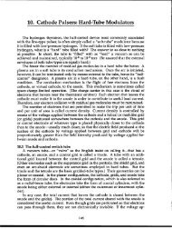
Figure 8-1 shows the cross section of a diode (or cathode-controlled electron<br />
gun), which is the simplest of all electron guns. It consists of a thermionically<br />
emitting cathode, a heater, a focus electrode, and an anode. The heater raises the<br />
cathode temperature high enough for it to become an efficient emitter of electrons.<br />
The focus electrode is electrically connected to the cathode, and its shape<br />
4“//<br />
L“/ /<br />
0// 10///,<br />
Anodeand tuba<br />
w<br />
Cathcda<br />
Heater<br />
c insulator<br />
Figure8-10cross.<br />
-section<br />
u<br />
viewof a diode,or cathode-controlledelectrongun.<br />
65
66 High-Power Microwave-Tube Transmitters<br />
Tuba<br />
Entrarlca !0 Iwn tunnel<br />
Ceramichigh-voltageInsulator<br />
f<br />
Modulating-anodetennin<br />
-,<br />
Ceramichbhwoilaga insulator<br />
{<br />
r: m<br />
CathodetarminalJ h<br />
Heatertarmlnal—<br />
Figure 8-2. Fligh-power microwave-tube electron gun with modulating anode.<br />
is important to the electrostatic lens formed between cathode and anode. (It is<br />
also the terminus of most of the high-voltage arcs, reducing the likelihood of arc<br />
damage to the cathode surface itself.) The anode is usually the entrance to the<br />
beam tunnel of the amplifier device. There is only one electrode to which pulse<br />
modulation can be applied and that is the cathode. (The cathode heater power<br />
source must, of course, be capable of being floated atop the cathode modulation<br />
pulse.)<br />
8.2 Modulating anode<br />
Some time ago, it occurred to engineers at ElMAC, who designed and built<br />
large CW klystrons for UHF television service and tropospheric-scatter communications,<br />
that if the electrode serving the function of the anode in the diode gun<br />
were insulated from both the cathode and the body of the tube, some interesting<br />
properties might be obtained. The original intent of their “isolated anode” was<br />
to mitigate the effects of internal gun arcing. If, for instance, the anode was<br />
maintained at a voltage near ground by connecting it to ground through a resistor,<br />
an arc between cathode and the isolated anode would simply pull the anode<br />
down to cathode potential and result in nothing more than the shutting off the<br />
beam current. If the electrode can be used to shut off beam current, it can also be<br />
used to turn it on, hence the alternative appellation “modulating anode.”<br />
The modulating anode is an electrode of cylindrical geometry placed between<br />
the cathode and drift-tube entrance. The example shown in cross-sectional view
PuIse Modulators (8) 67<br />
[ //// ~’ / //fiA~<br />
.,<br />
,.,.. 4/ . .<br />
/<br />
Anodeor tubeMy<br />
Focuselectrod+<br />
Grid<br />
Anodeor tub<br />
body<br />
/<br />
Heater<br />
.Cathode<br />
Heater<br />
$<br />
Figure 8-3. Cross-section view of electron gun with<br />
insulated focus electrode.<br />
Figure 8-4. Cross-section view of electron gun<br />
with intercepting p“d.<br />
in Fig. 8-2 is of an electron gun whose cathode operates at approximately 100 kV<br />
negative with respect to body (ground). The pulse voltage applied to a modulating<br />
anode is usually a large fraction of the cathode voltage (50°/0or more) and is<br />
often pulsed to within a few hundred volts of ground during the beam-current<br />
pulse. The particular geometry illustrated is typically operated at 70% cathode<br />
voltage (70-kV pulse with respect to cathode, 30-kV negative with respect to<br />
ground). The convergent electron beam, the outer edges of which have been<br />
shown with dashed lines, is magnetically and electrostatically focused so that<br />
only a tiny fraction (0.19’0) of the total beam current is intercepted by the modulating<br />
anode. Therefore, it takes virtually no power to drive it. The load the<br />
anode presents to the pulsed-voltage source is predominantly capacitance, made<br />
up of its internal capacitance and the self-capacitance of the modulator itself<br />
(which, as we will see, can be the largest component).<br />
8.3 Insulated-focus electrode<br />
As shown in Fig. 8-1, the focus electrode in a diode-type electron gun is<br />
connected to the cathode. As shown in Fig. 8-3, it can also be insulated from the<br />
cathode, in which case a voltage can be applied between the focus electrode and<br />
cathode. During the interpulse interval, this voltage can be sufficiently negative<br />
to inhibit the flow of electrons leaving the cathode, and during the pulse it can<br />
either be at cathode voltage or even positive with respect to the cathode. As with<br />
the modulating-anode electron gun, the cathode voltage in this device is continuously<br />
applied. The voltage swing required between beam cutoff and fullbeam<br />
conduction is less for the focus electrode than for the modulating anode,<br />
but the effect on beam shape during the rise-and-fall intervals is greater.<br />
8.4 Intercepting control grid<br />
Requiring even less voltage swing between beam cutoff and full conduction is<br />
the intercepting control grid, illustrated in Fig. 8-4. The grid is a radially connected<br />
mesh of concentric circles that is set directly in the path of the electron
I<br />
68 High-Power Microwave-Tube Transmitters<br />
Sandad-gr!d<br />
stmcture<br />
rid<br />
grid<br />
Cathode<br />
Healer<br />
I<br />
I<br />
I<br />
‘w<br />
Figure 8-5. Cross-section view of electron gun<br />
with control and shadow ~“ds.<br />
Figure 8-6. Cut-away view of electron gun<br />
with bonded-grid control electrode. -<br />
beam. Therefore, it is going to intercept some fraction of the total cathode<br />
current whenever its voltage is positive with respect to the cathode. This interception<br />
current not only subtracts from the available interaction beam current,<br />
but it causes the grid wires to heat and, eventually to become secondary electron<br />
emitters, which severely limits the pulse energy and average-power capabilities<br />
of tubes that use them.<br />
8.5 Shadow-gridded gun<br />
The shadow-gridded gun, illustrated in Fig. 8-5, uses an electrode called the<br />
shadow grid that is at cathode potential, has the same pattern as the control grid,<br />
and is positioned between the control grid and the cathode so as to inhibit electrons<br />
whose paths would cause them to strike the control grid.<br />
8.6 Bonded-grid gun<br />
An extension of the shadow-grid concept is the bonded-grid structure, shown<br />
in Fig. 8-6. Here, an integrated assembly consisting of the grid and an insulating<br />
substrate having the same shape is directly bonded to the cathode surface. In<br />
some cases, it is even embedded in the cathode surface so that the plane of the<br />
grid is virtually flush with that of the cathode.<br />
8.7 E-gun considerations<br />
What, then, are the considerations that determine which type of microwavetube<br />
electron gun is appropriate and what type of pulse modulator should go<br />
with it?<br />
The choice is simple if the power levels involved exceed those that can be<br />
achieved with a tube that can operate with continuously applied cathode voltage.<br />
The theoretical upper limit of this voltage is approximately 150 kV. However,<br />
there are few practical systems that operate reliably at much more than 100 kV.<br />
The gray region, therefore, is between 100 kV and 150 kV. Above 150 kV there is<br />
no choice but to use a diode gun with a cathode pulser (and the shorter the pulse,
Pulse Modulators (8) 69<br />
the greater the voltage that can be applied before the interval between gun arcs<br />
becomes the limitation). Between 150 kV and 200 kV, cathode pulses, whose<br />
durations can range from 40 ps at the high-voltage end to 100 us at the lowvoltage<br />
end, have proven practical. Between 200 kV and 300 kV, practical pulse<br />
durations shrink from 40 P down to 1-2 p.s. In the submicrosecond-pulse range,<br />
cathode voltages up to 1 MV are not necessarily outrageous.<br />
On the other hand, the~ are situations where cathode pulsing is most inappropriate,<br />
such as for a microwave tube that is unstable if its cathode voltage is<br />
less than its intended operating voltage. (The coupled-cavity TWT is a notorious<br />
example.) Cathode pulsing of such a tube can give rise to “rabbit ears,” which<br />
are periods of RF oscillation during the rise-and-fall intervals of cathode voltage<br />
as the voltage passes through regions of instability. Tubes of such power—<br />
greater than 100 kW peak power is a fuzzy criterion—almost always have electron<br />
guns with modulating anodes. Even though these modulating anodes have<br />
pulse voltages applied to them that maybe less than the total beam voltage, the<br />
electrons that enter the drift region of the tube will all have the same initial<br />
velocity. This velocity is determined only by the total accelerating voltage, which<br />
is the voltage between cathode and ground. (Guns whose modulating-anode<br />
voltage is significantly smaller than the cathode voltage-say, 50% or so-are<br />
called velocity-jump guns because the electron-beam velocity jumps as it enters<br />
the drift space beyond the modulating anode.)<br />
The tube with the modulating-anode gun and pulser is also superior to the<br />
cathode modulator in high-duty-factor, high-average-power applications because<br />
the modulator, as we will see, handles only a small fraction of the total beam<br />
power. These advantages shrink as the system pulse repetition rate increases,<br />
and at some point greater than 5000 pps—another fuzzy criterion-the microwave-tube<br />
gun must have a low-voltage control grid and a grid modulator to go<br />
with it. Worthy of consideration in the gray region between high-PRF grid control<br />
and high-average-power, high-duty-factor modulating-anode control is control<br />
by means of the focus electrode, which is located physically and electrically<br />
between them.