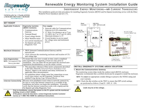
Renewable Energy Monitoring System Installation Guide
Renewable Energy Monitoring System Installation Guide
Renewable Energy Monitoring System Installation Guide
You also want an ePaper? Increase the reach of your titles
YUMPU automatically turns print PDFs into web optimized ePapers that Google loves.
<strong>Renewable</strong> <strong>Energy</strong> <strong>Monitoring</strong> <strong>System</strong> <strong>Installation</strong> <strong>Guide</strong><br />
INDEPENDENT ENERGY MONITORING—MA CURRENT TRANSDUCERS<br />
This installation guide provides procedures for installing Engenuity <strong>System</strong>s eBOXX and Fat Spaniel monitoring service with the Elkor<br />
WattsOn Power transducer and mA CTs.<br />
GET READY<br />
Applicable Products<br />
Maximum Distances<br />
Auto-Registration<br />
NOTE: Not required if Site<br />
Survey provided.<br />
Documentation<br />
Internet Connectivity<br />
Engenuity <strong>System</strong>s<br />
eBOXX Contents:<br />
• Communications<br />
Gateway<br />
• Terminal Board<br />
• Fused voltage blocks<br />
• Elkor WattsOn meter<br />
• mA current transducers<br />
• Fat Spaniel cgConfig<br />
Diagnostic Tool<br />
You supply:<br />
• Network cable for Communications<br />
Gateway-to-LAN connection<br />
• CT Wire: For distances up to 5' use<br />
12 AWG; for 5' to 15' use 10 AWG.<br />
Maximum distance is 15'.<br />
• Circuit breaker in service panel<br />
for voltage sense and instrument<br />
power<br />
• Recommended: Laptop PC with<br />
Engenuity’s Insight Installer <br />
a<br />
• 300 ft. between Communications Gateway and the<br />
network port<br />
• 120 ft. between the monitoring enclosure and location of CTs<br />
and voltage taps<br />
To ensure that your view is ready on time, send a completed<br />
auto-registration to Engenuity at least two days prior to<br />
installation. You can either fill out and return the enclosed autoregistration<br />
documentation, or use the online version.<br />
• This procedure references Elkor meter components described<br />
in the Elkor WattsOn Universal Power Transducer User<br />
Manual. Adhere to all cautions and safety instructions in<br />
applicable Elkor documentation.<br />
• For guidelines about voltage sense line connections on non<br />
screw-type contact, use the Engenuity Technical Note<br />
entitled Using Spring Cage Terminal Blocks.<br />
Because most installation issues relate to network connectivity,<br />
be sure to verify that Internet connectivity is available at the<br />
installation site before you begin this installation. If possible,<br />
verify that the Internet connection works with a laptop and the<br />
Fat Spaniel cgConfig Diagnostic Tool.<br />
Prior to installation, ensure that power to the PV system and the monitored<br />
building circuit is SHUT DOWN.<br />
If the power cannot be shut down, contact Engenuity <strong>System</strong>s Customer<br />
Service at 1-480-782-5600 for additional instructions.<br />
INSTALL ENGENUITY SYSTEMS eBOXX SOLUTION<br />
1. Mount the Communications Gateway<br />
The monitoring system ships inside the outdoor-rated eBOXX enclosure.<br />
Engenuity recommends that a certified electrician be assigned to install the enclosure.<br />
NOTE: You must use appropriate conduit fittings to preserve the NEMA rating and<br />
your warranty.<br />
NOTE: Check the dip switches on the TB25 to ensure that DIP switch settings<br />
are positioned as follows: 2 and 3 = OFF, 1 = ON.<br />
Leads may be at line voltage.<br />
IEM mA Current Transducers Page 1 of 2
<strong>Renewable</strong> <strong>Energy</strong> <strong>Monitoring</strong> <strong>System</strong> <strong>Installation</strong> <strong>Guide</strong><br />
INDEPENDENT ENERGY MONITORING—MA CTS<br />
INSTALL ENGENUITY SYSTEMS eBOXX SOLUTION (Continued)<br />
2. Set up the Data Connection<br />
If your meter is in the same enclosure as the Communication Gateway,<br />
the data connection is prewired. If, however, you have additional meters or other<br />
Modbus devices outside the gateway enclosure, these must be daisy-chained.<br />
The wires used in testing your system are left in the appropriate terminals as<br />
connection markers. Refer to the table below.<br />
the table below.<br />
Engenuity Termination Board<br />
Elkor RS485 Terminals<br />
1 (unused)<br />
2 +<br />
3 -<br />
4 GND<br />
• To connect to the LAN (if you are not using the modem option) connect the<br />
network cable to the LAN1 port on the Communications Gateway.<br />
3. Connect Voltage Sense and Instrument Power Conductors<br />
a. Install a circuit breaker in the load panel and run voltage taps in conduit to the<br />
monitoring enclosure.<br />
b. Connect your voltage taps to the fused voltage blocks in your monitoring<br />
assembly. Your system may be built with a second set of L1 and N voltage<br />
blocks. These are for instrument power, which you may take from the monitored<br />
circuit or from a separate circuit of 120, 208, 230, or 240 VAC.<br />
c. Be sure to attach a ground to the labeled spring clip terminal. The system must be<br />
grounded for both accuracy and safety.<br />
4. Connect the Current Transducers<br />
a. Wire the CT leads directly to the Elkor meter,<br />
matching the wire number to the corresponding<br />
number on the meter.<br />
b. Note the polarity arrow on your CT, and install<br />
the CTs per the attached wiring diagram:<br />
• For PV <strong>Installation</strong>:<br />
The CT polarity indicator must face toward<br />
the inverter.<br />
• For Building Demand <strong>Installation</strong><br />
The CT polarity indicator must face toward<br />
the utility meter.<br />
INSTALL ENGENUITY SYSTEMS eBOXX SOLUTION (Continued)<br />
5. Power Up the Enclosure: Connect AC Power Source<br />
Turn on the instrument power circuit. Check for the green power light on the<br />
24VDC transformer, and the red power LED on the Communications Gateway.<br />
6. Check the Power LED on the Elkor Meter: Look for Green PWR LED.<br />
7. Power Up the Communications Gateway and Check LEDs<br />
Condition LED Location Indication Description<br />
Power Up READY Gateway front<br />
panel<br />
LAN1<br />
activity<br />
Serial<br />
activity<br />
8. Power Up the Voltage Sensors<br />
If you have not done so with the instrument power, energize the circuit for the<br />
voltage taps.<br />
9. Check Data Connectivity<br />
If you have a laptop and the Fat Spaniel cgConfig Diagnostic Tool, verify that the<br />
Communications Gateway can connect and that the monitoring devices are visible<br />
to the Communications Gateway.<br />
10. Log into Solar Plant Vision (SPV) under Assets tab to confirm installation<br />
of Logger(s) and Device(s).<br />
a<br />
LINK<br />
TX/RX<br />
Gateway LAN1<br />
port<br />
Gateway front<br />
panel<br />
Green flicker<br />
Green steady<br />
Flicker<br />
Flicker<br />
<strong>System</strong> is booting up.<br />
<strong>System</strong> is ready.<br />
LAN traffic transmission<br />
occurring to inverter.<br />
Transmit (TX) and Receive<br />
(RX) activity to inverter.<br />
TROUBLESHOOTING TIPS<br />
• Make sure the Communications Gateway ethernet cable is connected before<br />
TROUBLESHOOTING TIPS<br />
connecting the monitoring device to power.<br />
• Make sure the Communications Gateway ethernet cable is connected<br />
• before Verify connecting that all connections the monitoring are solidly device seated. to power.<br />
• • Verify Verify that that all the connections Internet cabling are solidly does seated. not exceed 300 ft.<br />
• • Test V erify for that Internet the Internet connectivity cabling with doe a LA laptop. LAPs not exceed 300 ft.<br />
• Test for Internet connectivity with a laptop.<br />
ENGENUITY SYSTEMS TECHNICAL SUPPORT<br />
Phone: 1-480-782-5600 or 1-800-375-3363<br />
tech@engenuity.com<br />
Copyright © 2010 Engenuity <strong>System</strong>s, Inc. All rights reserved.<br />
IEM mA Current Transducers Page 2 of 2


