L-DALI User Manual - Engenuity Systems, Inc.
L-DALI User Manual - Engenuity Systems, Inc.
L-DALI User Manual - Engenuity Systems, Inc.

You also want an ePaper? Increase the reach of your titles
YUMPU automatically turns print PDFs into web optimized ePapers that Google loves.
L-<strong>DALI</strong><br />
BACnet/<strong>DALI</strong> Gateway<br />
<strong>User</strong> <strong>Manual</strong><br />
LOYTEC electronics GmbH
L-<strong>DALI</strong> <strong>User</strong> <strong>Manual</strong> 2 LOYTEC<br />
This page is intentionally left blank!<br />
Version 1.0<br />
LOYTEC electronics GmbH
L-<strong>DALI</strong> <strong>User</strong> <strong>Manual</strong> 3 LOYTEC<br />
Contact<br />
LOYTEC<br />
Stolzenthalergasse 24/3<br />
A-1080 Vienna<br />
AUSTRIA/EUROPE<br />
support@loytec.com<br />
http://www.loytec.com<br />
Version 1.0<br />
Document No. 88071901<br />
LOYTEC MAKES AND YOU RECEIVE NO WARRANTIES OR CONDITIONS,<br />
EXPRESS, IMPLIED, STATUTORY OR IN ANY COMMUNICATION WITH YOU, AND<br />
LOYTEC SPECIFICALLY DISCLAIMS ANY IMPLIED WARRANTY OF<br />
MERCHANTABILITY OR FITNESS FOR A PARTICULAR PURPOSE.<br />
No part of this publication may be reproduced, stored in a retrieval system, or transmitted, in<br />
any form or by any means, electronic, mechanical, photocopying, recording, or otherwise,<br />
without the prior written permission of LOYTEC.<br />
L-Chip, LC7093 and L-CORE are trademarks of LOYTEC.<br />
Version 1.0<br />
LOYTEC electronics GmbH
L-<strong>DALI</strong> <strong>User</strong> <strong>Manual</strong> 4 LOYTEC<br />
Contents<br />
1 Introduction..............................................................................................................................8<br />
1.1 Overview............................................................................................................................8<br />
1.2 Scope..................................................................................................................................8<br />
2 Quick-Start Guide.................................................................................................................... 9<br />
2.1 Installation of the L-<strong>DALI</strong>.................................................................................................9<br />
2.2 Configuration of the L-<strong>DALI</strong>.......................................................................................... 10<br />
2.2.1 IP Configuration via Console....................................................................................10<br />
2.2.2 IP Configuration via Web Interface.......................................................................... 11<br />
2.2.3 BACnet Configuration.............................................................................................. 13<br />
2.2.4 <strong>DALI</strong> Configuration..................................................................................................14<br />
2.3 Using the L-<strong>DALI</strong>............................................................................................................17<br />
3 Enclosure and Installation......................................................................................................18<br />
3.1 Enclosure......................................................................................................................... 18<br />
3.2 Product Label...................................................................................................................18<br />
3.3 Mounting..........................................................................................................................19<br />
3.4 LED Signals.....................................................................................................................19<br />
3.4.1 Power LED................................................................................................................19<br />
3.4.2 Status LED................................................................................................................ 19<br />
3.4.3 Ethernet Link LED.................................................................................................... 19<br />
3.4.4 Ethernet Activity LED.............................................................................................. 19<br />
3.4.5 Ethernet Config LED.................................................................................................19<br />
3.4.6 Ethernet CN/IP LED................................................................................................. 19<br />
3.4.7 MSTP Activity LED..................................................................................................19<br />
3.4.8 <strong>DALI</strong> Activity LEDs.................................................................................................19<br />
3.5 Buttons.............................................................................................................................20<br />
3.5.1 Status Button............................................................................................................. 20<br />
3.5.2 <strong>DALI</strong> Mode Button................................................................................................... 20<br />
3.5.3 <strong>DALI</strong> Channel Button............................................................................................... 20<br />
3.5.4 <strong>DALI</strong> Program Button...............................................................................................21<br />
3.6 DIP-Switch Settings.........................................................................................................21<br />
3.7 Power Supply...................................................................................................................21<br />
3.8 Terminal Layout.............................................................................................................. 22<br />
3.9 Wiring.............................................................................................................................. 22<br />
Version 1.0<br />
LOYTEC electronics GmbH
L-<strong>DALI</strong> <strong>User</strong> <strong>Manual</strong> 5 LOYTEC<br />
4 Console Interface................................................................................................................... 24<br />
4.1 Self Test...........................................................................................................................24<br />
4.2 L-<strong>DALI</strong> Configuration Menu (Main Menu)....................................................................25<br />
4.2.1 Option 1 – Show device information........................................................................ 25<br />
4.2.2 Option 2 – Update firmware......................................................................................25<br />
4.2.3 Option 3 – System configuration.............................................................................. 25<br />
4.2.4 Option 4 – <strong>DALI</strong> maintenance.................................................................................. 26<br />
4.2.5 Option 5 – IP configuration.......................................................................................26<br />
4.2.6 Option 7 – BACnet configuration............................................................................. 26<br />
4.2.7 Option 8 – Reset configuration (factory defaults).....................................................26<br />
4.2.8 Option 9 – Device statistics.......................................................................................26<br />
4.2.9 Option 0 – Reset L-<strong>DALI</strong>..........................................................................................26<br />
4.3 System Configuration Menu............................................................................................26<br />
4.3.1 Option 7 – FTP server, 8 – FTP server port..............................................................26<br />
4.3.2 Option 9 – Web server, 0 – Web server port.............................................................27<br />
4.4 <strong>DALI</strong> Maintenance Menu................................................................................................27<br />
4.4.1 Option 1 – <strong>DALI</strong> channel..........................................................................................27<br />
4.4.2 Option 2 – <strong>DALI</strong> configuration.................................................................................27<br />
4.4.3 Option 3 – <strong>DALI</strong> statistics........................................................................................ 27<br />
4.4.4 Option 4 – <strong>DALI</strong> analyzer.........................................................................................29<br />
4.5 <strong>DALI</strong> Configuration Menu..............................................................................................29<br />
4.5.1 Option 1 – List devices, 2 – Scan & list devices.......................................................29<br />
4.5.2 Option 3 – Auto-assign devices................................................................................ 30<br />
4.5.3 Option 4 – Recover devices...................................................................................... 30<br />
4.5.4 Option 5 – Replace missing devices......................................................................... 30<br />
4.5.5 Option 0 – Reset network..........................................................................................31<br />
4.5.6 Option a – Add device...............................................................................................31<br />
4.5.7 Option c – Configure device..................................................................................... 31<br />
4.5.8 Option d – Delete device..........................................................................................31<br />
4.5.9 Option w – Wink device............................................................................................31<br />
4.5.10 Option o – Add OSRAM device............................................................................. 31<br />
4.5.11 Option r – Read OSRAM CIN................................................................................ 31<br />
4.6 <strong>DALI</strong> Device Configuration Menu..................................................................................32<br />
4.6.1 Option 1 – Group membership..................................................................................32<br />
4.6.2 Option 2 – Power on level.........................................................................................32<br />
Version 1.0<br />
LOYTEC electronics GmbH
L-<strong>DALI</strong> <strong>User</strong> <strong>Manual</strong> 6 LOYTEC<br />
4.6.3 Option 3 – System failure level.................................................................................32<br />
4.6.4 Option 4 – Minimum level........................................................................................ 33<br />
4.6.5 Option 5 – Maximum level....................................................................................... 33<br />
4.6.6 Option 6 – Fade rate..................................................................................................33<br />
4.6.7 Option 7 – Fade time.................................................................................................33<br />
4.6.8 Option 8 – Test dim (rate), 9 – Test dim (time)........................................................ 33<br />
4.7 IP Configuration Menu....................................................................................................33<br />
4.7.1 Option 1 – DHCP...................................................................................................... 34<br />
4.7.2 Option 2 – IP Address, 3 - IP Netmask, 4 - IP Gateway...........................................34<br />
4.7.3 Option 5 – Hostname, 6 - Domainname....................................................................35<br />
4.7.4 Option 7 – DNS Servers............................................................................................35<br />
4.7.5 Option 9 – MAC Address..........................................................................................35<br />
4.7.6 Option b – Link Speed & Duplex..............................................................................35<br />
4.8 BACnet Configuration Menu.......................................................................................... 35<br />
4.8.1 Option 1 – Device ID................................................................................................ 36<br />
4.8.2 Option 2 – Device name, 3 – Device description, 4 – Device location.................... 36<br />
4.8.3 Option 9 – Data Link Layer...................................................................................... 36<br />
4.8.4 Option 0 – Configure Data Link Layer..................................................................... 36<br />
4.9 Reset Configuration Menu...............................................................................................38<br />
4.9.1 Option 1 – Reset everything to factory defaults........................................................38<br />
4.9.2 Option 2 – Reset all passwords................................................................................. 38<br />
4.10 Device Statistics Menu.................................................................................................. 38<br />
4.10.1 Option 4 – IP statistics............................................................................................ 38<br />
4.10.2 Option 7 – BACnet statistics...................................................................................40<br />
5 Web Interface.........................................................................................................................41<br />
5.1 Start Screen and Account Management...........................................................................41<br />
5.2 Device Information..........................................................................................................43<br />
5.3 Device Configuration.......................................................................................................43<br />
5.3.1 System Configuration................................................................................................43<br />
5.3.2 <strong>DALI</strong> Configuration..................................................................................................44<br />
5.3.3 IP Configuration........................................................................................................47<br />
5.3.4 BACnet Configuration.............................................................................................. 49<br />
5.4 Device Statistics...............................................................................................................50<br />
5.4.1 IP Statistics................................................................................................................50<br />
5.4.2 <strong>DALI</strong> Statistics..........................................................................................................51<br />
Version 1.0<br />
LOYTEC electronics GmbH
L-<strong>DALI</strong> <strong>User</strong> <strong>Manual</strong> 7 LOYTEC<br />
5.5 Reset, Contact, Logout.................................................................................................... 52<br />
6 BACnet Interface................................................................................................................... 53<br />
6.1 Data Link Layers............................................................................................................. 53<br />
6.2 BACnet objects................................................................................................................53<br />
6.2.1 Device Object............................................................................................................53<br />
6.2.2 Analog Output Object............................................................................................... 57<br />
6.2.3 Multi-State Output Object.........................................................................................62<br />
7 <strong>DALI</strong> Interface.......................................................................................................................66<br />
7.1 Compatibility................................................................................................................... 66<br />
7.1.1 Supported Ballasts.....................................................................................................66<br />
7.1.2 Multi-Master Operation.............................................................................................66<br />
7.1.3 Vendor Specific Extensions...................................................................................... 66<br />
7.2 Installation Scenarios.......................................................................................................66<br />
7.2.1 Installation in a Single-Master Environment............................................................ 66<br />
7.2.2 Installation in a Multi-Master Environment..............................................................67<br />
7.2.3 Replacement of a Single Broken <strong>DALI</strong> device.........................................................67<br />
7.2.4 Replacement of Multiple Broken <strong>DALI</strong> devices.......................................................68<br />
7.2.5 Replacement of Broken L-<strong>DALI</strong>...............................................................................68<br />
8 Updating the L-<strong>DALI</strong> Firmware............................................................................................69<br />
8.1 Firmware Update via FTP............................................................................................... 69<br />
8.2 Firmware Update via the Console................................................................................... 70<br />
9 Troubleshooting..................................................................................................................... 72<br />
9.1 Technical Support............................................................................................................72<br />
10 Application Notes................................................................................................................ 73<br />
11 L-<strong>DALI</strong> Firmware Versions.................................................................................................74<br />
12 Specifications.......................................................................................................................75<br />
13 Revision History.................................................................................................................. 76<br />
Version 1.0<br />
LOYTEC electronics GmbH
L-<strong>DALI</strong> <strong>User</strong> <strong>Manual</strong> 8 LOYTEC<br />
1 Introduction<br />
1.1 Overview<br />
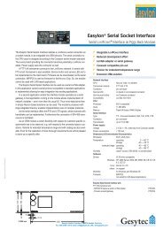
The L-<strong>DALI</strong> gateway enables Light Control through a BACnet interface. <strong>DALI</strong> (Digital<br />
Addressable Lighting Interface) is part of the IEC 60929 standard. It is used to dim and<br />
switch luminaires from most of the leading European manufacturers. <strong>DALI</strong> also supports<br />
devices like multi-sensors (e.g. for brightness, movement, temperature, etc.) and intelligent<br />
switches. L-<strong>DALI</strong> provides 4 independent <strong>DALI</strong> channels and can control up to 64 <strong>DALI</strong>based<br />
luminaires per <strong>DALI</strong> channel individually.<br />
All luminaires are monitored for defective lamps. L-<strong>DALI</strong> can provide this information to the<br />
Building Management System (BMS) through its BACnet interface. On the BACnet side<br />
L-<strong>DALI</strong> supports BACnet/IP and BACnet MS/TP.<br />
The complete L-<strong>DALI</strong> configuration can be performed through the built-in Web server or a<br />
console interface. Thus, the commissioning and maintenance of the <strong>DALI</strong> system can be<br />
done using a standard Web browser on a PC.<br />
Figure 1: The L-<strong>DALI</strong> can handle up to four <strong>DALI</strong> channels.<br />
1.2 Scope<br />
This document covers L-<strong>DALI</strong> devices with firmware version 1.0. See Section 11 for<br />
differences between the different L-<strong>DALI</strong> firmware versions. It is assumed the reader is<br />
familiar with the basic concepts of BACnet and <strong>DALI</strong>.<br />
Version<br />
LOYTEC electronics GmbH
L-<strong>DALI</strong> <strong>User</strong> <strong>Manual</strong> 9 LOYTEC<br />
2 Quick-Start Guide<br />
2.1 Installation of the L-<strong>DALI</strong><br />
It is recommended to use the L<strong>DALI</strong>-PWR4-230 power supply together with the L-<strong>DALI</strong>.<br />
Connect the L-<strong>DALI</strong> to the L<strong>DALI</strong>-PWR4-230 and to the <strong>DALI</strong> network as shown in Figure<br />
2. To allow for easy configuration it is recommended to always connect the L-<strong>DALI</strong> to the<br />
Ethernet network.<br />
Figure 2: Wiring the L-<strong>DALI</strong>.<br />
After the <strong>DALI</strong> ballasts have been installed and connected to the <strong>DALI</strong> network, the<br />
installation can be tested by following these steps:<br />
1. Check that the <strong>DALI</strong> LEDs (“<strong>DALI</strong> x ACT”, where x is 1 to 4) do not light up red. If one<br />
of these LEDs are red, check the proper connection of the bus power supply for the<br />
corresponding channel.<br />
2. Press the <strong>DALI</strong> mode button (“ON/OFF/AUTO”) on the front panel of the L-<strong>DALI</strong> once.<br />
Now all <strong>DALI</strong> ballasts should be switched on (maximum level) and the <strong>DALI</strong> LEDs on<br />
the L-<strong>DALI</strong> should light up green.<br />
Version<br />
LOYTEC electronics GmbH
L-<strong>DALI</strong> <strong>User</strong> <strong>Manual</strong> 10 LOYTEC<br />
3. Press the <strong>DALI</strong> mode button again. Now all <strong>DALI</strong> ballasts should be switched off and the<br />
<strong>DALI</strong> LEDs on the L-<strong>DALI</strong> should light up orange.<br />
4. Press the <strong>DALI</strong> mode button again. This should not change the state of the <strong>DALI</strong> ballasts<br />
but return the L-<strong>DALI</strong> to the auto-mode (control via BACnet interface).<br />
If the L-<strong>DALI</strong> is connected to a BACnet MS/TP network, the MS/TP EIA-485 network must<br />
be properly terminated with a termination resistance of 120 ohms connected at each of the<br />
two ends of the segment medium. Figure 3 shows how to connect the L-<strong>DALI</strong> to an MS/TP<br />
network.<br />
Figure 3: Connect the L-<strong>DALI</strong> to a BACnet MS/TP network.<br />
2.2 Configuration of the L-<strong>DALI</strong><br />
The L-<strong>DALI</strong> can be configured via console interface or via Web interface. To configure the<br />
L-<strong>DALI</strong> the following steps have to be performed:<br />
1. Setup IP configuration (see Sections 2.2.1 and 2.2.2).<br />
2. Setup BACnet configuration (see Section 2.2.3).<br />
3. Setup <strong>DALI</strong> configuration (see Section 2.2.4).<br />
Note: This setup procedure assumes the use of the IP interface. Alternatively, a<br />
configuration via the console interface is possible. See Section 4.2 for details.<br />
2.2.1 IP Configuration via Console<br />
Use a PC terminal program with communication settings of 38,400 bps / 8 data bits / no parity<br />
/ 1 stop bit / no handshake. To connect COM1 of the PC to the Console on the L-<strong>DALI</strong>, use a<br />
standard null-modem-cable with full handshaking. Power up the L-<strong>DALI</strong> or press Return if<br />
the L-<strong>DALI</strong> is already running. The following menu should appear on the terminal:<br />
Version<br />
LOYTEC electronics GmbH
L-<strong>DALI</strong> <strong>User</strong> <strong>Manual</strong> 11 LOYTEC<br />
Device Main Menu<br />
================<br />
[1] Show device information<br />
[2] Serial firmware upgrade<br />
[3] System configuration<br />
[4] <strong>DALI</strong> maintenance<br />
[5] IP configuration<br />
[7] BACnet configuration<br />
[8] Reset configuration (factory defaults)<br />
[9] Device statistics<br />
[0] Reset device<br />
Please choose:<br />
Figure 4: Main L-<strong>DALI</strong> menu.<br />
Select 5 from the L-<strong>DALI</strong> main menu and enter the IP address, netmask, and gateway<br />
address. Note that you must use different IP addresses if you are using multiple L-<strong>DALI</strong>s in<br />
your setup. See Section for 4.7 details.<br />
IP Configuration Menu<br />
=====================<br />
[1] DHCP : disabled<br />
[2] IP Address : 192.168.1.254<br />
[3] IP Netmask : 255.255.255.0<br />
[4] IP Gateway : 192.168.1.1<br />
[5] Hostname : new<br />
[6] Domainname : <br />
[7] DNS Servers : <br />
[9] MAC Address : 00 0A B0 01 02 DB (factory default)<br />
[b] Link Speed & Duplex : Auto Detect<br />
[q] Quit without saving<br />
[x] Exit and save<br />
Please choose:<br />
Figure 5: Enter basic IP settings.<br />
Press x to save the IP settings and reset the L-<strong>DALI</strong> with main menu item 0 in order to let the<br />
new IP settings take effect.<br />
2.2.2 IP Configuration via Web Interface<br />
Optionally to using the console interface one can also use the Web interface to configure the<br />
L-<strong>DALI</strong>. In a web browser, enter the default IP address 192.168.1.254 of the L-<strong>DALI</strong>. Note<br />
that if your PC has an IP address in a subnet other than 192.168.1.xxx, you must open a<br />
command tool and enter the following route command to add a route to the L-<strong>DALI</strong>:<br />
Windows START -> Run<br />
command.com<br />
Route add 192.168.1.254 %COMPUTERNAME%<br />
Version<br />
LOYTEC electronics GmbH
L-<strong>DALI</strong> <strong>User</strong> <strong>Manual</strong> 12 LOYTEC<br />
Figure 6: L-<strong>DALI</strong> Start Screen.<br />
Click on “Config” in the left menu. You will be asked to enter the administrator password in<br />
order to change the IP settings. Enter “admin” and select Login.<br />
Figure 7: Enter admin as the default administrator password.<br />
The Config menu opens. Click on “IP” in the Config menu and enter the IP address, the IP<br />
netmask, and IP gateway for this L-<strong>DALI</strong> as shown in Figure 8.<br />
Version<br />
LOYTEC electronics GmbH
L-<strong>DALI</strong> <strong>User</strong> <strong>Manual</strong> 13 LOYTEC<br />
Figure 8: Enter IP address and gateway.<br />
Press Save Settings and then reset the device by selecting “reset” in the highlighted text. This<br />
changes the IP settings of the L-<strong>DALI</strong>.<br />
2.2.3 BACnet Configuration<br />
To configure the BACnet interface, at least the device ID must be configured (see Figure 9).<br />
Figure 9: BACnet device configuration.<br />
Version<br />
LOYTEC electronics GmbH
L-<strong>DALI</strong> <strong>User</strong> <strong>Manual</strong> 14 LOYTEC<br />
The device ID corresponds to the instance number of the device object. It must be unique,<br />
BACnet internetwork-wide.<br />
By default the BACnet/IP data link layer is used. If the L-<strong>DALI</strong> must be used with BACnet<br />
MS/TP data link layer please refer to Section 5.3.4 for further information.<br />
2.2.4 <strong>DALI</strong> Configuration<br />
To configure a fresh <strong>DALI</strong> channel, the following steps must be performed:<br />
Figure 10: <strong>DALI</strong> configuration page.<br />
Step 1: Go to <strong>DALI</strong> configuration page, select the channel and press “Rescan Channel”<br />
button (see Figure 10).<br />
Step 2: After the scan finished successfully, press the “Back” button. Now all <strong>DALI</strong> devices<br />
should be listed under “Scanned Devices not in Database” as shown in Figure 11.<br />
Version<br />
LOYTEC electronics GmbH
L-<strong>DALI</strong> <strong>User</strong> <strong>Manual</strong> 15 LOYTEC<br />
Figure 11: After the device scan all <strong>DALI</strong> devices on the channel are listed.<br />
Figure 12: All devices on the channel are auto-assigned.<br />
Step 3: Press the “Auto Assign” button as shown in Figure 11. This will assign a short<br />
address to all unconfigured devices on the channel (see Figure 12).<br />
Step 4: Press the “Back” button. Now all <strong>DALI</strong> devices should have a short address<br />
assigned and should be listed under “Devices in Database” as shown in Figure 13.<br />
Version<br />
LOYTEC electronics GmbH
L-<strong>DALI</strong> <strong>User</strong> <strong>Manual</strong> 16 LOYTEC<br />
Figure 13: All devices are configured and can be winked.<br />
Step 5: By executing the wink function, the installer now can determine which devices were<br />
assigned to which <strong>DALI</strong> short addresses (and thus to which BACnet objects).<br />
Figure 14: Configure a <strong>DALI</strong> device.<br />
Version<br />
LOYTEC electronics GmbH
L-<strong>DALI</strong> <strong>User</strong> <strong>Manual</strong> 17 LOYTEC<br />
Step 6: Optionally the devices can be assigned to groups. For this purpose, press the<br />
“Config” button next to the device. Now the <strong>DALI</strong> device configuration page<br />
appears (see Figure 14). To make a device member of a specific group, the<br />
checkbox associated with this group must be checked. To make the changed settings<br />
take effect the “Save Settings” button must be pressed.<br />
Repeat steps 1 to 6 for all <strong>DALI</strong> channels.<br />
Important: In case the L-<strong>DALI</strong> is operated in a <strong>DALI</strong> multi-master environment please<br />
follow the steps described in Section 7.2.2!<br />
2.3 Using the L-<strong>DALI</strong><br />
The <strong>DALI</strong> ballasts connected to the <strong>DALI</strong> interfaces of the L-<strong>DALI</strong> can be controlled via the<br />
BACnet interface either by controlling each single ballast via analog output objects, by<br />
controlling groups of ballasts via analog output objects, or by scene control via multi-state<br />
output objects.<br />
In case of the analog output objects, each <strong>DALI</strong> ballast and each <strong>DALI</strong> group has a<br />
corresponding analog output object. See Section 6.2.2 for which object is assigned to which<br />
<strong>DALI</strong> ballast or <strong>DALI</strong> group respectively.<br />
Now, the dim level of the device or group can be controlled with the “Present_Value”<br />
property of the object. If “ramping” or “fading” is used, can be configured with the vendor<br />
specific “Dim_Mode” property. In case of the analog output objects corresponding to <strong>DALI</strong><br />
ballasts, the <strong>DALI</strong> properties “fade time”, “fade rate”, “min level”, “max level”, “power on<br />
level”, and “system failure level” correspond to the vendor specific properties “Fade_Time”,<br />
“Ramp_Rate”, “Min_Pres_Value”, “Max_Pres_Value”, “Power_On_Level”, and<br />
“System_Failure_Level” respectively.<br />
A permanent communication failure between the L-<strong>DALI</strong> and the ballast, a lamp failure, or a<br />
failure of the ballast is signaled with the “Out_Of_Service” property and the corresponding<br />
flag in the property “Status_Flags”. In case the current dim level is overridden via the button<br />
interface on the front panel of the L-<strong>DALI</strong> (see Section 3.5.2), the corresponding OVERRIDE<br />
flag in the property “Status_Flags” is set. For details see Section 6.2.2.<br />
For scene control the L-<strong>DALI</strong> offers 17 multi-state output objects. Each object controls the<br />
<strong>DALI</strong> scenes of a <strong>DALI</strong> group (0-15), while the last object controls the <strong>DALI</strong> scenes in all<br />
devices of a <strong>DALI</strong> channel (broadcast). Set the “Present_Value” of the objects to recall,<br />
store, and erase scenes. Use states 2-17 of each object to recall scenes 0-15 respectively,<br />
states 18-34 to store the current dim levels as scene 0-15 respectively and states 35-49 to<br />
erase scenes 0-15 respectively. For details see Section 6.2.3.<br />
Version<br />
LOYTEC electronics GmbH
L-<strong>DALI</strong> <strong>User</strong> <strong>Manual</strong> 18 LOYTEC<br />
3 Enclosure and Installation<br />
3.1 Enclosure<br />
The L-<strong>DALI</strong> enclosure is 9 TE (1 TE = 17.5 mm) wide for DIN rail mounting, following DIN<br />
43 880 (see Figure 15).<br />
Prog<br />
Button<br />
Channel Mode<br />
Button Button<br />
<strong>DALI</strong> MS/TP CNIP<br />
LEDs LED LEDs<br />
Ethernet<br />
LEDs<br />
Console<br />
Connector<br />
Power<br />
LED<br />
Status<br />
Button<br />
Figure 15: L-<strong>DALI</strong> enclosure (dimensions in mm).<br />
3.2 Product Label<br />
The product label on the right side of the L-<strong>DALI</strong> contains the following information:<br />
♦ L-<strong>DALI</strong> order number with bar-code (e.g. L<strong>DALI</strong>-ME204)<br />
♦ Serial number with bar-code (Ser #)<br />
♦ Ethernet MAC ID with bar-code (MAC1)<br />
Unless otherwise stated, all bar-codes are encoded using “Code 128”.<br />
An additional label is also supplied with the L-<strong>DALI</strong> for documentation purpose.<br />
Version<br />
LOYTEC electronics GmbH
L-<strong>DALI</strong> <strong>User</strong> <strong>Manual</strong> 19 LOYTEC<br />
3.3 Mounting<br />
The device comes prepared for mounting on DIN rails following DIN EN 50 022.<br />
The device can be mounted in any position. However, an installation place with proper<br />
airflow must be selected to ensure that the L-<strong>DALI</strong> temperature does not exceed the specified<br />
range (see Section 11).<br />
3.4 LED Signals<br />
3.4.1 Power LED<br />
The L-<strong>DALI</strong> power LED lights up green when power is supplied to terminals 24, 25, and 26.<br />
3.4.2 Status LED<br />
Currently the Status LED has no function.<br />
3.4.3 Ethernet Link LED<br />
The Ethernet Link LED lights up green whenever an Ethernet cable is plugged in and a<br />
physical connection with a switch, hub, or PC can be established.<br />
3.4.4 Ethernet Activity LED<br />
The Ethernet Activity LED lights up green for 6 ms whenever a packet is transmitted or<br />
received or when a collision is detected on the network cable.<br />
3.4.5 Ethernet Config LED<br />
Currently the Ethernet Config LED has no function.<br />
3.4.6 Ethernet CN/IP LED<br />
The Ethernet CN/IP LED light up green for 25 ms whenever a BACnet packet is transmitted<br />
or received via the BACnet/IP data link layer.<br />
3.4.7 MSTP Activity LED<br />
The MSTP Activity LED lights up green for 25 ms whenever a BACnet packet is transmitted<br />
or received via the BACnet MS/TP data link layer.<br />
3.4.8 <strong>DALI</strong> Activity LEDs<br />
Each <strong>DALI</strong> interface on the L-<strong>DALI</strong> has a three color LED (green, red and orange). Table 1<br />
shows different LED patterns and their meaning.<br />
Version<br />
LOYTEC electronics GmbH
L-<strong>DALI</strong> <strong>User</strong> <strong>Manual</strong> 20 LOYTEC<br />
Behavior<br />
Description<br />
GREEN flashing Traffic<br />
RED flashing fast Traffic with errors<br />
RED permanent No bus power-supply/bus-power supply failed<br />
ORANGE<br />
Override to all off or interface is selected<br />
permanent<br />
GREEN permanent Override to all on<br />
Table 1: <strong>DALI</strong> Activity LED patterns<br />
3.5 Buttons<br />
3.5.1 Status Button<br />
The L-<strong>DALI</strong> is equipped with a status button (see Figure 15). When pressing the status<br />
button shortly during normal operation of the L-<strong>DALI</strong>, it sends a BACnet “I-Am” message on<br />
all active BACnet data link layers.<br />
3.5.2 <strong>DALI</strong> Mode Button<br />
The L-<strong>DALI</strong> is equipped with a <strong>DALI</strong> mode button (“ON/OFF/AUTO”, see Figure 15). It is<br />
used to manually override the dim values of the attached <strong>DALI</strong> devices. Press it once and all<br />
<strong>DALI</strong> devices on the selected channels are switched on (“on mode”), press it again and all<br />
<strong>DALI</strong> devices on the selected channels are switched off (“off mode”), press it a third time and<br />
the selected channels go back to “auto mode”.<br />
In the “on mode” and “off mode” the dim levels of the <strong>DALI</strong> devices cannot be changed via<br />
the BACnet interface (“manual override”). In the “auto mode” the dim level of the <strong>DALI</strong><br />
devices is controlled via the BACnet interface.<br />
Channels are selected via the <strong>DALI</strong> Channel button (see Section 3.5.3). The current state of a<br />
<strong>DALI</strong> channel can be determined based on the corresponding <strong>DALI</strong> Activity LED (see<br />
Section 3.4.8).<br />
The main purpose of the mode button is to test the wiring during installation of the <strong>DALI</strong><br />
system.<br />
3.5.3 <strong>DALI</strong> Channel Button<br />
The L-<strong>DALI</strong> is equipped with a <strong>DALI</strong> Channel button (“CHANNEL”, see Figure 15). It is<br />
used to select a specific channel. All other functions which can be performed via the <strong>DALI</strong><br />
button interface (e.g. select <strong>DALI</strong> mode, see Section 3.5.2) are applied only to the selected<br />
<strong>DALI</strong> channel(s).<br />
By default all <strong>DALI</strong> channels are selected. If the <strong>DALI</strong> Channel button is pressed once the<br />
first channel is selected and the corresponding <strong>DALI</strong> Activity LED lights up orange. Now<br />
each time the button is pressed the next channel is selected. If the last <strong>DALI</strong> channel is<br />
selected and the button is pressed once again, all <strong>DALI</strong> channels are selected. If no button is<br />
pressed for more than 15 seconds, the current selection is canceled.<br />
Version<br />
LOYTEC electronics GmbH
L-<strong>DALI</strong> <strong>User</strong> <strong>Manual</strong> 21 LOYTEC<br />
3.5.4 <strong>DALI</strong> Program Button<br />
The L-<strong>DALI</strong> is equipped with a <strong>DALI</strong> Program button (“PROG”, see Figure 15). It is used to<br />
replace a broken ballast. When the button is pressed, the L-<strong>DALI</strong> scans the selected <strong>DALI</strong><br />
channel for missing and unconfigured ballasts. If exactly one missing ballast and one<br />
unconfigured ballast is found on a channel, the unconfigured ballast is used to replace the<br />
missing ballast. That is, the unconfigured ballast is configured with the address and the<br />
configuration parameters of the missing ballast. If multiple missing ballasts or multiple<br />
unconfigured ballasts are found, the console UI or the Web UI must be used to replace the<br />
missing ballast(s) (see Section 4.5.4 and 5.3.2).<br />
During the replace operation, the <strong>DALI</strong> Activity LED of the corresponding channel lights up<br />
orange. If the operation was successful, the LED lights up green for 0,5 seconds, if it failed,<br />
the LED lights up red for 0,5 seconds.<br />
Which channels are selected can be controlled via the <strong>DALI</strong> Channel button (see Section<br />
3.5.3).<br />
3.6 DIP-Switch Settings<br />
The L-<strong>DALI</strong> uses 7 switches to select the mode of operation.<br />
The DIP switch assignment for the L-<strong>DALI</strong> is shown in Table 2.<br />
DIP<br />
<strong>DALI</strong> #<br />
Function<br />
Factory Default<br />
Settings<br />
1 Reserved OFF<br />
2 Reserved OFF<br />
3 Reserved ON<br />
4 Must be OFF OFF<br />
5 Reserved OFF<br />
6 Reserved OFF<br />
7 Reserved OFF<br />
Table 2: DIP switch settings for the L-<strong>DALI</strong>.<br />
3.7 Power Supply<br />
The L-<strong>DALI</strong> can either be DC or AC powered (see Table 3).<br />
Terminal Function Note<br />
24 Main Earth Ground<br />
25, 26 Power Inputs 12-35 VDC or<br />
12-24 VAC<br />
± 10%<br />
Table 3: Power Terminals for L-<strong>DALI</strong><br />
Important: Do not ground one of the power supply wires on terminal 26 as shown in<br />
Figure 2!<br />
Version<br />
LOYTEC electronics GmbH
L-<strong>DALI</strong> <strong>User</strong> <strong>Manual</strong> 22 LOYTEC<br />
We highly recommend the following power supply for use with the L-<strong>DALI</strong>:<br />
Manufacturer: LOYTEC electronics GmbH.<br />
Manufacturer part number: L<strong>DALI</strong>-PWR4-230<br />
Description: Power Supply, 1 x 24 V DC, 4 x <strong>DALI</strong> bus power supply 16 V DC output, 230V<br />
AC 50 Hz input, max. 170 mA<br />
This power supply can be used to provide the 24 V DC supply voltage for the L-<strong>DALI</strong> as well<br />
as the <strong>DALI</strong> bus power for the four <strong>DALI</strong> interfaces.<br />
3.8 Terminal Layout<br />
The L-<strong>DALI</strong> provides screw terminals to connect to four <strong>DALI</strong> networks, the BACnet MS/TP<br />
network, as well as to the power supply. The screw terminals can be used for wires with a<br />
maximum thickness of 1.5 mm 2 /AWG12.<br />
Terminal<br />
Function<br />
13 BACnet MS/TP Reference<br />
14 BACnet MS/TP Non-Inverting Input<br />
15 BACnet MS/TP Inverting Input<br />
24 Main Earth Ground<br />
25, 26 Power Supply (do not connect 26 to ground)<br />
27, 28 <strong>DALI</strong> Channel 4<br />
29, 30 <strong>DALI</strong> Channel 3<br />
32, 33 <strong>DALI</strong> Channel 2<br />
34, 35 <strong>DALI</strong> Channel 1<br />
Table 4: L-<strong>DALI</strong> Terminals.<br />
3.9 Wiring<br />
Connect the L-<strong>DALI</strong> to the L<strong>DALI</strong>-PWR4-230 and to the <strong>DALI</strong> network as shown in Figure<br />
2. For easy configuration, it is recommended to always connect the L-<strong>DALI</strong> to the Ethernet<br />
network.<br />
Note: The L-<strong>DALI</strong> does not provide the <strong>DALI</strong> bus power supply for any of the connected<br />
<strong>DALI</strong> channels. Thus, on each <strong>DALI</strong> channel a proper externaL-<strong>DALI</strong> bus power<br />
supply must be provided. For this purpose LOYTEC recommends the use of<br />
LOYTEC’s <strong>DALI</strong> bus power supply L<strong>DALI</strong>-PWR4-230, which is capable of providing<br />
the 24 V DC supply voltage for the L-<strong>DALI</strong> as well as the <strong>DALI</strong> bus power for the four<br />
<strong>DALI</strong> interfaces. If some other <strong>DALI</strong> masters are connected to the <strong>DALI</strong> channel,<br />
these devices might generate the <strong>DALI</strong> bus power internally, in which case no<br />
additional bus power supply must be connected to this channel.<br />
Version<br />
LOYTEC electronics GmbH
L-<strong>DALI</strong> <strong>User</strong> <strong>Manual</strong> 23 LOYTEC<br />
If the L-<strong>DALI</strong> is connected to a BACnet MS/TP network, the MS/TP EIA-485 network must<br />
be properly terminated with a termination resistance of 120 ohms connected at each of the<br />
two ends of the segment medium. Figure 3 shows how to connect the L-<strong>DALI</strong> to an MS/TP<br />
network.<br />
Version<br />
LOYTEC electronics GmbH
L-<strong>DALI</strong> <strong>User</strong> <strong>Manual</strong> 24 LOYTEC<br />
4 Console Interface<br />
The L-<strong>DALI</strong> is equipped with a serial interface to<br />
♦ display the results of the self test<br />
♦ allow advanced configuration via a console menu<br />
♦ upgrade the L-<strong>DALI</strong> firmware<br />
To use the serial interface, the console connector (see Figure 15) of the L-<strong>DALI</strong> can be<br />
connected to the RS-232 port of a PC. The PC can communicate with the L-<strong>DALI</strong> using a<br />
standard terminal program with communication settings of 38,400 bps / 8 data bits / no<br />
parity / 1 stop bit. Use a standard null-modem-cable with full handshaking to connect the<br />
L-<strong>DALI</strong> serial console interface to your PC.<br />
4.1 Self Test<br />
Whenever the L-<strong>DALI</strong> comes out of reset it performs a self test.<br />
The console output of a successful boot sequence on an L-<strong>DALI</strong> reads as follows:<br />
LOYTEC electronics GmbH<br />
www.loytec.com<br />
Testing Board ID (2)<br />
Testing RAM<br />
Testing boot loader<br />
Testing fallback image<br />
Testing primary image<br />
Testing Flash<br />
Loading primary image<br />
Passed<br />
Passed<br />
Passed<br />
Passed<br />
Passed<br />
Passed<br />
Passed<br />
Bootloader version 2<br />
L-<strong>DALI</strong> Primary Image loading...<br />
Firmware version 1.0.0<br />
Type bootshell to enter the boot shell...<br />
Mounting file system<br />
Starting <strong>DALI</strong> channel 1<br />
Starting <strong>DALI</strong> channel 2<br />
Starting <strong>DALI</strong> channel 3<br />
Starting <strong>DALI</strong> channel 4<br />
Starting TCP/IP networking<br />
Starting FTP server<br />
Starting BACnet networking<br />
Starting <strong>DALI</strong> gateway application<br />
Passed<br />
Passed<br />
Passed<br />
Passed<br />
Passed<br />
Passed<br />
Passed<br />
Passed<br />
Done<br />
L-<strong>DALI</strong>(c)<br />
LOYTEC electronics GmbH<br />
Tue Aug 1 12:22:54 2006 - V1.0.0<br />
Figure 16: Console messages during the boot phase.<br />
The duration of the L-<strong>DALI</strong> boot sequence is typically 2 minutes.<br />
Version<br />
LOYTEC electronics GmbH
L-<strong>DALI</strong> <strong>User</strong> <strong>Manual</strong> 25 LOYTEC<br />
4.2 L-<strong>DALI</strong> Configuration Menu (Main Menu)<br />
After booting the L-<strong>DALI</strong> displays the following console menu:<br />
Device Main Menu<br />
================<br />
[1] Show device information<br />
[2] Serial firmware upgrade<br />
[3] System configuration<br />
[4] <strong>DALI</strong> maintenance<br />
[5] IP configuration<br />
[7] BACnet configuration<br />
[8] Reset configuration (factory defaults)<br />
[9] Device statistics<br />
[0] Reset device<br />
Please choose:<br />
Figure 17: L-<strong>DALI</strong> main menu.<br />
The menu items are described below in the following sections.<br />
4.2.1 Option 1 – Show device information<br />
This menu item shows information on the L-<strong>DALI</strong> and the current firmware. The output<br />
should look like Figure 18.<br />
Device Information<br />
==================<br />
Product: L-<strong>DALI</strong><br />
Product code: L<strong>DALI</strong>-ME204<br />
Firmware: L-<strong>DALI</strong> Primary Image<br />
Version: 1.0.0<br />
Build date: Tue Aug 20 12:22:54 2006<br />
Serial number: 008801-000AB001285A<br />
Free memory: 11495K,81K<br />
Press to continue<br />
Figure 18: Device information.<br />
4.2.2 Option 2 – Update firmware<br />
This menu item allows updating the L-<strong>DALI</strong> firmware via the serial interface (console). See<br />
Section 8.2 for detailed instructions.<br />
Note: If you select this option accidentally, you can return to the main menu by sending a<br />
break signal. In case your terminal program does not offer an option to send a break<br />
signal, the device must be reset to return to the main menu.<br />
4.2.3 Option 3 – System configuration<br />
Select this menu item to change system configuration settings. See Section 4.3 for details.<br />
Version<br />
LOYTEC electronics GmbH
L-<strong>DALI</strong> <strong>User</strong> <strong>Manual</strong> 26 LOYTEC<br />
4.2.4 Option 4 – <strong>DALI</strong> maintenance<br />
Select this menu item to install, configure, and service the connected <strong>DALI</strong> network. See<br />
Section 4.4 for details.<br />
4.2.5 Option 5 – IP configuration<br />
Select this menu item to change the IP configuration settings like IP address, default gateway,<br />
DHCP, or MAC address. See Section 4.5.11 for details.<br />
4.2.6 Option 7 – BACnet configuration<br />
Select this menu item to change the BACnet configuration settings like device ID, device<br />
name, and data link layer related configuration setting. See Section 4.8 for details.<br />
4.2.7 Option 8 – Reset configuration (factory defaults)<br />
This menu item resets the L-<strong>DALI</strong> to factory defaults. See Section 4.9 for details.<br />
4.2.8 Option 9 – Device statistics<br />
Select this menu item to display advanced IP and BACnet device statistics information like<br />
number of packets sent and received, etc. See Section 4.10 for details.<br />
4.2.9 Option 0 – Reset L-<strong>DALI</strong><br />
This menu item resets the L-<strong>DALI</strong>.<br />
4.3 System Configuration Menu<br />
The system configuration menu holds various system configuration settings. Typically the<br />
system configuration menu looks like shown in Figure 19.<br />
System Configuration Menu<br />
=========================<br />
[7] FTP server : enabled<br />
[8] FTP server port : 21 (default)<br />
[9] Web server : enabled<br />
[0] Web server port : 80 (default)<br />
[q] Quit without saving<br />
[x] Exit and save<br />
Please choose:<br />
Figure 19: System configuration menu.<br />
4.3.1 Option 7 – FTP server, 8 – FTP server port<br />
Allows to enable and disable the FTP server and configure the FTP server port. Press to<br />
toggle between enabled and disabled. Press to change the FTP server port. To use the<br />
default port enter 0 when asked for the port number. The FTP server is used for instance to<br />
update the firmware (see Section 8.1).<br />
Version<br />
LOYTEC electronics GmbH
L-<strong>DALI</strong> <strong>User</strong> <strong>Manual</strong> 27 LOYTEC<br />
4.3.2 Option 9 – Web server, 0 – Web server port<br />
These menu items allow enabling and disabling the Web server and configure the Web server<br />
port on the L-<strong>DALI</strong>. You can disable the Web server if you do not want to provide access to<br />
the L-<strong>DALI</strong> configuration via the Web interface. Press to toggle between enabled and<br />
disabled. Press to change the Web server port. To use the default port, enter 0 when<br />
asked for the port number.<br />
4.4 <strong>DALI</strong> Maintenance Menu<br />
The <strong>DALI</strong> maintenance menu is used to configure the devices connected to the <strong>DALI</strong><br />
channels and perform diagnostics of the <strong>DALI</strong> network. Typically the <strong>DALI</strong> maintenance<br />
menu looks like shown in Figure 20.<br />
<strong>DALI</strong> Maintenance Menu<br />
=====================<br />
[1] <strong>DALI</strong> channel : 1<br />
[2] <strong>DALI</strong> configuration<br />
[3] <strong>DALI</strong> statistics<br />
[4] <strong>DALI</strong> analyzer<br />
[q] Quit<br />
Please choose:<br />
Figure 20: <strong>DALI</strong> maintenance menu.<br />
4.4.1 Option 1 – <strong>DALI</strong> channel<br />
This menu item allows to change the selected <strong>DALI</strong> channel. All other menu items relate to<br />
the currently selected <strong>DALI</strong> channel.<br />
4.4.2 Option 2 – <strong>DALI</strong> configuration<br />
Select this menu item to install and configure devices on the selected <strong>DALI</strong> channel. See<br />
Section 4.5 for details.<br />
4.4.3 Option 3 – <strong>DALI</strong> statistics<br />
This menu item shows the statistic counters of the selected <strong>DALI</strong> channel. These counters<br />
offer valuable information when looking for problems in a <strong>DALI</strong> network. A typical output is<br />
shown in Figure 21.<br />
Version<br />
LOYTEC electronics GmbH
L-<strong>DALI</strong> <strong>User</strong> <strong>Manual</strong> 28 LOYTEC<br />
<strong>DALI</strong> interface statistics<br />
=========================<br />
Date/Time of clear (GMT) : Tue Aug 8 13:29:12 2006<br />
Bus supply<br />
: ok<br />
Packets sent : 211<br />
Packets received : 75<br />
Bus supply failures : 0<br />
Collisions : 0<br />
Noise : 0<br />
Code violations : 0<br />
Start bit errors : 0<br />
Frame errors : 0<br />
Late responses : 0<br />
Invalid settling time : 0<br />
Clear <strong>DALI</strong> interface statistics (y/n)?<br />
Figure 21: Typical output of the <strong>DALI</strong> interface statistics.<br />
“Date/Time of clear (GMT)” shows the date and time, the <strong>DALI</strong> statistics for this interface<br />
were cleared the last time.<br />
“Bus supply” shows the current status of the <strong>DALI</strong> bus power supply. If the status is “failed”,<br />
check if the <strong>DALI</strong> network is properly powered and the L-<strong>DALI</strong> is properly connected to the<br />
<strong>DALI</strong> network (see Section 3.9 for wiring details).<br />
“Packets sent” shows the number of <strong>DALI</strong> commands and queries send by the L-<strong>DALI</strong>.<br />
“Packets received” shows the number of <strong>DALI</strong> messages received by the L-<strong>DALI</strong>. This<br />
includes responses to queries sent by the L-<strong>DALI</strong> as well as messages sent by other <strong>DALI</strong><br />
masters connected to the same <strong>DALI</strong> network.<br />
“Bus supply failures” shows the number of times a <strong>DALI</strong> bus power supply failure was<br />
detected. A bus power supply failure is detected if the <strong>DALI</strong> signal goes low for more than<br />
2,5 milliseconds.<br />
“Collisions” shows the number of times the L-<strong>DALI</strong> has detected a collision on the <strong>DALI</strong><br />
network. A collision is typically detected if some other <strong>DALI</strong> master sends a message<br />
simultaneously to the L-<strong>DALI</strong>. If this counter is counting up continuously and there are<br />
problems with the operation of the L-<strong>DALI</strong> there might be another <strong>DALI</strong> master on the<br />
network, which is not capable of multi-master operation.<br />
“Noise” shows a characteristic value for noise in the <strong>DALI</strong> network. This counter is<br />
increased every time the <strong>DALI</strong> signal goes low for less than 200 microseconds.<br />
“Code violations” shows the number of packets which were received with a code violation. A<br />
code violation is encountered if the frame format does not follow the specification for <strong>DALI</strong><br />
networks.<br />
“Start bit errors” shows the number of received packets without a valid start bit.<br />
“Frame errors” shows the number of received packets with an unknown frame format.<br />
Unknown frames might be generated by <strong>DALI</strong> devices which use vendor specific extensions<br />
to the <strong>DALI</strong> protocol or which use newer <strong>DALI</strong> protocol versions not supported by the<br />
L-<strong>DALI</strong> firmware. Please check if your L-<strong>DALI</strong> firmware is up-to-date.<br />
Version<br />
LOYTEC electronics GmbH
L-<strong>DALI</strong> <strong>User</strong> <strong>Manual</strong> 29 LOYTEC<br />
“Late responses” shows the number of responses which could not be assigned to <strong>DALI</strong><br />
queries, because they were received later than 19 milliseconds after a query.<br />
“Invalid settling time” shows the number of times the settling time between two <strong>DALI</strong><br />
packets was shorter than the minimum time specified for the <strong>DALI</strong> protocol. If this counter is<br />
counting up continuously and there are problems with the operation of the L-<strong>DALI</strong>, there<br />
might be another <strong>DALI</strong> master on the network, which is not capable of multi-master<br />
operation.<br />
After the statistics were displayed the user can choose, whether he wants to reset the statistic<br />
counters.<br />
4.4.4 Option 4 – <strong>DALI</strong> analyzer<br />
When this menu item is selected, the built in <strong>DALI</strong> protocol analyzer is started. Press<br />
to stop logging and return to the L-<strong>DALI</strong> maintenance menu.<br />
4.5 <strong>DALI</strong> Configuration Menu<br />
The <strong>DALI</strong> configuration menu is used to configure the devices connected to the selected<br />
<strong>DALI</strong> channels. Typically the <strong>DALI</strong> configuration menu looks like shown in Figure 22.<br />
<strong>DALI</strong> Configuration Menu<br />
=======================<br />
[1] List devices<br />
[2] Scan & list devices<br />
[3] Auto-assign devices<br />
[4] Recover devices<br />
[5] Replace missing devices<br />
[0] Reset network<br />
[a] Add device<br />
[c] Configure device<br />
[d] Delete device<br />
[w] Wink device<br />
[o] Add OSRAM device<br />
[r] Read OSRAM CIN<br />
[q] Quit<br />
Please choose:<br />
Figure 22: <strong>DALI</strong> configuration menu.<br />
4.5.1 Option 1 – List devices, 2 – Scan & list devices<br />
This menu options show all devices connected to the selected <strong>DALI</strong> interface and some<br />
additional information. “List devices” (Option 1) only scans the <strong>DALI</strong> network in case no<br />
scan has been performed before or some changes have occurred to the <strong>DALI</strong> network. “Scan<br />
& list devices” (Option 2) always leads to a (re-)scan of the network. A typical output of this<br />
menu option is shown in Figure 23.<br />
Version<br />
LOYTEC electronics GmbH
L-<strong>DALI</strong> <strong>User</strong> <strong>Manual</strong> 30 LOYTEC<br />
Rand Short Type Cfg Status CIN<br />
-----------------------------------------------------------<br />
0x64A8F7 00 000 * OK -<br />
0x76CB2A 01 000 * OK -<br />
Figure 23: List <strong>DALI</strong> devices.<br />
The column “Rand” gives the random number identifying the <strong>DALI</strong> device. Note that in<br />
<strong>DALI</strong> systems, these random numbers might change under certain circumstances.<br />
The column “Short” gives the short address of the <strong>DALI</strong> device. A <strong>DALI</strong> device must have a<br />
short address assigned for operation.<br />
The column “Type” shows the <strong>DALI</strong> device type of the <strong>DALI</strong> device. Currently, only device<br />
type 0 (“fluorescent lamp”) is specified.<br />
The column “Cfg” shows if a device is configured and present in the <strong>DALI</strong> device database of<br />
the L-<strong>DALI</strong> – that is – if it is operational. Operable devices have a “*” in this column.<br />
The column “Status” shows the current status of the <strong>DALI</strong> device.<br />
The column “CIN” shows the OSRAM CIN of the <strong>DALI</strong> device, if known. The OSRAM<br />
CIN is a unique serial number only present in OSRAM <strong>DALI</strong> devices.<br />
4.5.2 Option 3 – Auto-assign devices<br />
This menu option allows to automatically assign <strong>DALI</strong> short addresses to all unconfigured<br />
<strong>DALI</strong> devices in the selected <strong>DALI</strong> network. All new devices are added to the L-<strong>DALI</strong>’s<br />
<strong>DALI</strong> device database. It is typically used to install a <strong>DALI</strong> network with no other <strong>DALI</strong><br />
master.<br />
4.5.3 Option 4 – Recover devices<br />
This menu option allows to recover a <strong>DALI</strong> database from an already installed <strong>DALI</strong><br />
network. It is typically used in the following cases:<br />
♦ An L-<strong>DALI</strong> is broken and must be replaced. In this case, the recover function can be used<br />
to retrieve the existing configuration of the <strong>DALI</strong> network. This way, the new L-<strong>DALI</strong><br />
can replace the broken one, while still keeping the existing <strong>DALI</strong> network configuration.<br />
♦ The L-<strong>DALI</strong> is used in a multi-master environment but the L-<strong>DALI</strong> is not used to install<br />
the <strong>DALI</strong> network. In this case, the recover function can be used after the network was<br />
installed to update the L-<strong>DALI</strong> on how the network is configured.<br />
4.5.4 Option 5 – Replace missing devices<br />
This menu option allows to manually replace broken <strong>DALI</strong> devices. Once the broken device<br />
is physically replaced by a new one, this option is used to configure the new <strong>DALI</strong> device<br />
with the configuration of the replaced one. This menu option searches for all missing<br />
(offline) <strong>DALI</strong> devices and tries to match them with new and unconfigured devices.<br />
Version<br />
LOYTEC electronics GmbH
L-<strong>DALI</strong> <strong>User</strong> <strong>Manual</strong> 31 LOYTEC<br />
Note: If only a single <strong>DALI</strong> ballast must be replaced, it is easier to use the PROG button on<br />
the front of the L-<strong>DALI</strong> instead of this menu option (see Section 3.5.4)!<br />
4.5.5 Option 0 – Reset network<br />
This menu option is used to reset all devices in the <strong>DALI</strong> network to factory defaults. Use<br />
this option only if a persistent problem occurs when trying to configure devices. It resets all<br />
<strong>DALI</strong> related configuration in the L-<strong>DALI</strong> and in the <strong>DALI</strong> devices in the network and thus<br />
allows to start the configuration process from scratch.<br />
4.5.6 Option a – Add device<br />
Use this option to manually configure a <strong>DALI</strong> device and add it to the L-<strong>DALI</strong>’s database.<br />
First the device must be chosen. For this purpose a list of all unconfigured devices is shown.<br />
Then an unused short address in the range 0 to 63 must be entered. Finally the chosen device<br />
gets the selected short address assigned and is added to the L-<strong>DALI</strong>’s database.<br />
4.5.7 Option c – Configure device<br />
This menu option allows to configure the <strong>DALI</strong> registers of a selected <strong>DALI</strong> device and<br />
assign it to groups. Only <strong>DALI</strong> devices which are in the L-<strong>DALI</strong> database can be configured.<br />
See Section 4.6 for details.<br />
4.5.8 Option d – Delete device<br />
This menu option is used to delete a <strong>DALI</strong> device from the L-<strong>DALI</strong>’s database and reset it to<br />
factory defaults.<br />
4.5.9 Option w – Wink device<br />
This menu option is used to perform a wink operation on the selected <strong>DALI</strong> device.<br />
Typically a device that performs a wink action is dimmed to its minimum, then to its<br />
maximum, then back to its minimum, and finally back to its initial value before the wink<br />
action. Only <strong>DALI</strong> devices which are in the L-<strong>DALI</strong>’s database can be winked.<br />
4.5.10 Option o – Add OSRAM device<br />
This menu option is similar to the one described in Section 4.5.6. However, the device to be<br />
added is not chosen from a list, but rather an eight-byte OSRAM CIN must be entered. The<br />
OSRAM CIN is a unique serial number only present in OSRAM <strong>DALI</strong> devices.<br />
4.5.11 Option r – Read OSRAM CIN<br />
This menu option allows to read the OSRAM CIN. The OSRAM CIN is a unique serial<br />
number only present in OSRAM <strong>DALI</strong> devices. The CIN can only be read from <strong>DALI</strong><br />
devices which are in the L-<strong>DALI</strong> database.<br />
Version<br />
LOYTEC electronics GmbH
L-<strong>DALI</strong> <strong>User</strong> <strong>Manual</strong> 32 LOYTEC<br />
4.6 <strong>DALI</strong> Device Configuration Menu<br />
The <strong>DALI</strong> device configuration menu is used to configure <strong>DALI</strong> registers of <strong>DALI</strong> devices<br />
which are in the L-<strong>DALI</strong>’s database. Typically the <strong>DALI</strong> configuration menu looks like<br />
shown in Figure 24.<br />
Note: Most of the <strong>DALI</strong> registers can also be changed via BACnet properties (see Section<br />
6.2.2)!<br />
<strong>DALI</strong> Device Configuration<br />
=========================<br />
Short address : 1<br />
Random address : 0x321A37<br />
Device type : fluorescent lamp (000)<br />
[1] Group membership : 5 7<br />
[2] Power on level : 100.000 %<br />
[3] System failure level : 100.000 %<br />
[4] Minimum level (phys.) : 0.991 % (0.991 %)<br />
[5] Maximum level : 100.000 %<br />
[6] Fade rate : 7 (44.725 steps/s)<br />
[7] Fade time : 0 (0.000 s)<br />
[8] Test dim (rate)<br />
[9] Test dim (time)<br />
[q] Quit without saving<br />
[x] Exit and save<br />
Please choose:<br />
Figure 24: <strong>DALI</strong> device configuration menu.<br />
A header displays the short address and the random address as well as the <strong>DALI</strong> device type<br />
of the device. The menu provides the following options:<br />
4.6.1 Option 1 – Group membership<br />
This menu option allows to add and remove the device from <strong>DALI</strong> groups. There are 16<br />
<strong>DALI</strong> groups (0 to 15).<br />
4.6.2 Option 2 – Power on level<br />
This menu option allows to configure the value of the register “<strong>DALI</strong> power-on level”. This<br />
is the dim level, the <strong>DALI</strong> device will use after a power failure.<br />
Note: If the L-<strong>DALI</strong> is not affected by the power failure, it will automatically restore the last<br />
dim value for all devices affected by a power failure.<br />
4.6.3 Option 3 – System failure level<br />
This menu option allows to define the behavior of the <strong>DALI</strong> device in case of a system<br />
failure. A system failure might be the failure of the <strong>DALI</strong> bus power supply or if the <strong>DALI</strong><br />
bus line is interrupted. Enter the value the device should dim to in case of a system failure or<br />
enter the word “MASK” if the dim level of the device should not be changed.<br />
Version<br />
LOYTEC electronics GmbH
L-<strong>DALI</strong> <strong>User</strong> <strong>Manual</strong> 33 LOYTEC<br />
4.6.4 Option 4 – Minimum level<br />
This menu option allows to set the minimum dim level of the <strong>DALI</strong> device. The value in the<br />
brackets gives the physical minimum dim level of the device.<br />
4.6.5 Option 5 – Maximum level<br />
This menu option allows to set the maximum dim level of the <strong>DALI</strong> device.<br />
4.6.6 Option 6 – Fade rate<br />
This menu option allows to set the fade rate of the <strong>DALI</strong> device used for ramping. The<br />
possible fade rates can be chosen from a list.<br />
4.6.7 Option 7 – Fade time<br />
This menu option allows to set the fade time of the <strong>DALI</strong> device used for fading. The<br />
possible fade times can be chosen from a list.<br />
4.6.8 Option 8 – Test dim (rate), 9 – Test dim (time)<br />
This menu option allows to test the fade time or the fade rate respectively by allowing to<br />
manually dim the <strong>DALI</strong> device with the configured fade time or fade rate.<br />
4.7 IP Configuration Menu<br />
The IP configuration menu holds relevant IP settings. Here are some general guidelines for<br />
setting IP addresses, port numbers, and time values.<br />
Enter 0.0.0.0 to clear an IP address<br />
Enter 0 to select the default port number<br />
Enter 0 to disable a time setting.<br />
Press Return to keep the current setting.<br />
The IP configuration menu, when DHCP is disabled, is shown in Figure 25.<br />
Version<br />
LOYTEC electronics GmbH
L-<strong>DALI</strong> <strong>User</strong> <strong>Manual</strong> 34 LOYTEC<br />
IP Configuration Menu<br />
=====================<br />
[1] DHCP : disabled<br />
[2] IP Address : 192.168.1.254<br />
[3] IP Netmask : 255.255.255.0<br />
[4] IP Gateway : 192.168.1.1<br />
[5] Hostname : new<br />
[6] Domainname : <br />
[7] DNS Servers : <br />
[9] MAC Address : 00 0A B0 01 02 DB (factory default)<br />
[b] Link Speed & Duplex : Auto Detect<br />
[q] Quit without saving<br />
[x] Exit and save<br />
Please choose:<br />
Figure 25: IP configuration menu when DHCP is disabled.<br />
The IP configuration menu, when DHCP is enabled, is shown in Figure 26.<br />
IP Configuration Menu<br />
=====================<br />
[1] DHCP : enabled<br />
IP Address : 192.168.1.254<br />
IP Netmask : 255.255.255.0<br />
IP Gateway : 192.168.1.1<br />
[5] Hostname : ldali1<br />
Domainname<br />
: <br />
DNS Servers<br />
: <br />
[9] MAC Address : 00 0A B0 01 02 DB (factory default)<br />
[b] Link Speed & Duplex : Auto Detect<br />
[q] Quit without saving<br />
[x] Exit and save<br />
Please choose:<br />
Figure 26: IP configuration menu when DHCP is enabled.<br />
4.7.1 Option 1 – DHCP<br />
Switches between manual entry of the IP address, netmask, and gateway address or automatic<br />
configuration from a DHCP server. If DHCP is disabled, one must enter the configuration<br />
data described in the following sections. If DHCP is enabled, please skip menu items 2<br />
through 7.<br />
Press to toggle between “DHCP enabled” and “DHCP disabled”.<br />
4.7.2 Option 2 – IP Address, 3 - IP Netmask, 4 - IP Gateway<br />
Please enter the IP address for the L-<strong>DALI</strong> device, the netmask (e.g. 255.255.255.0), and the<br />
default gateway address.<br />
Version<br />
LOYTEC electronics GmbH
L-<strong>DALI</strong> <strong>User</strong> <strong>Manual</strong> 35 LOYTEC<br />
4.7.3 Option 5 – Hostname, 6 - Domainname<br />
“Hostname” and “Domainname” are optional entries and can be left empty. For some DHCP<br />
configurations it may be necessary to enter a hostname. Please contact your system<br />
administrator to get information on how to configure DHCP to acquire an IP address.<br />
4.7.4 Option 7 – DNS Servers<br />
You can configure up to 3 Domain Name Servers. Currently, these entries are not used.<br />
4.7.5 Option 9 – MAC Address<br />
The L-<strong>DALI</strong> comes configured with a unique MAC address. This address can be changed in<br />
order to clone the MAC address of a different device. Please contact your system<br />
administrator to avoid MAC address conflicts. After selecting menu item 9 the following<br />
message appears.<br />
Override factory MAC address (y/n):<br />
Enter “y” to input a new MAC address or enter “n” to clear the current MAC address and<br />
return to the factory default MAC address.<br />
4.7.6 Option b – Link Speed & Duplex<br />
If the L-<strong>DALI</strong> is operated with a 10Mbit/s-only hub the link speed should be switched from<br />
“Auto Detect” to “10Mbps/Half-Duplex”. With modern 100/10Mbit/s switches, this setting<br />
can be left as is.<br />
Change Link Speed & Duplex<br />
==========================<br />
[1] Auto Detect (default)<br />
[2] 100Mbps/Full-Duplex<br />
[3] 100Mbps/Half-Duplex<br />
[4] 10Mbps/Full-Duplex<br />
[5] 10Mbps/Half-Duplex<br />
4.8 BACnet Configuration Menu<br />
This menu allows to configure the BACnet interface of the L-<strong>DALI</strong>.<br />
configuration menu is shown in Figure 27.<br />
The BACnet<br />
Version<br />
LOYTEC electronics GmbH
L-<strong>DALI</strong> <strong>User</strong> <strong>Manual</strong> 36 LOYTEC<br />
BACnet Configuration Menu<br />
=========================<br />
[1] Device ID : 17800<br />
[2] Device name : L-<strong>DALI</strong><br />
[3] Device description : L-<strong>DALI</strong><br />
[4] Device location : unknown<br />
[9] Data Link Layer : BACnet/IP<br />
[0] Configure BACnet/IP Data Link Layer<br />
[q] Quit without saving<br />
[x] Exit and save<br />
Please choose:<br />
Figure 27: BACnet configuration menu.<br />
4.8.1 Option 1 – Device ID<br />
This configuration option allows to set the instance part of the “Object_Identifier” property of<br />
the BACnet Device object. Note that this instance number must be unique within the BACnet<br />
internetwork.<br />
4.8.2 Option 2 – Device name, 3 – Device description, 4 – Device location<br />
These menu items allow to set the value of the properties “Object_Name”, “Description”, and<br />
“Location” of the BACnet Device object.<br />
4.8.3 Option 9 – Data Link Layer<br />
This menu item allows to choose the BACnet data link layer used. The following options are<br />
given:<br />
Select Data Link Layer<br />
======================<br />
[1] BACnet/IP<br />
[2] MS/TP<br />
Please choose:<br />
4.8.4 Option 0 – Configure Data Link Layer<br />
Depending on the currently selected BACnet data link layer one of the following menus<br />
appears:<br />
4.8.4.1 BACnet/IP Configuration Menu<br />
The BACnet/IP configuration menu is shown in Figure 28. Its only option allows to set the<br />
UDP port used for the BACnet/IP protocol (Option 3). Enter a port number of 0 to use the<br />
default port (47808/0xBAC0). For details related to the BACnet/IP data link layer see<br />
Section 6.1.<br />
Version<br />
LOYTEC electronics GmbH
L-<strong>DALI</strong> <strong>User</strong> <strong>Manual</strong> 37 LOYTEC<br />
BACnet/IP Configuration Menu<br />
============================<br />
[3] BACnet/IP port : 47808 (default)<br />
[q] Quit without saving<br />
[x] Exit and save<br />
Please choose:<br />
Figure 28: BACnet/IP configuration menu.<br />
4.8.4.2 MS/TP Configuration Menu<br />
The BACnet/IP configuration menu is shown in Figure 29. For details related to the BACnet<br />
MS/TP data link layer see Section 6.1.<br />
MS/TP Configuration Menu<br />
========================<br />
[3] MS/TP node number : 127<br />
[4] Baud rate : 9600<br />
[5] Max info frames : 1<br />
[6] Max master : 127<br />
[q] Quit without saving<br />
[x] Exit and save<br />
Please choose:<br />
Figure 29: MS/TP configuration menu.<br />
The menu offers the following options:<br />
4.8.4.2.1 Option 3 – MS/TP node number<br />
This menu item is used to set the MS/TP node number of the L-<strong>DALI</strong>. It must be in the range<br />
0 to the number configured with the “Max master” configuration option.<br />
4.8.4.2.2 Option 4 – Baud rate<br />
This menu item allows to configure the baud rate on the MS/TP channel. Possible options are<br />
9600, 19200, and 38400 baud.<br />
4.8.4.2.3 Option 5 – Max info frames<br />
This menu item allows to set the maximum number of info frames on the MS/TP channel.<br />
The default value is 1. It is recommended to leave this configuration option at the default<br />
setting.<br />
4.8.4.2.4 Option6 – Max master<br />
This menu item allows to set the maximum number of masters on the MS/TP channel. The<br />
default value is 127. It is recommended to leave this configuration option at the default<br />
setting.<br />
Version<br />
LOYTEC electronics GmbH
L-<strong>DALI</strong> <strong>User</strong> <strong>Manual</strong> 38 LOYTEC<br />
4.9 Reset Configuration Menu<br />
This menu item allows resetting the device to its factory default state. The following menu<br />
appears.<br />
Reset Configuration Menu<br />
========================<br />
[1] Reset everything to factory defaults<br />
[3] Reset all passwords<br />
[q] Quit<br />
Please choose:<br />
Figure 30: Reset to factory defaults menu.<br />
4.9.1 Option 1 – Reset everything to factory defaults<br />
Select this menu item to reset the complete device to factory defaults (including error log<br />
etc.).<br />
4.9.2 Option 2 – Reset all passwords<br />
Select this menu item to reset all passwords (Web interface, FTP server, etc.) to factory<br />
defaults.<br />
4.10 Device Statistics Menu<br />
This menu holds relevant information regarding the device statistics of the L-<strong>DALI</strong>. The<br />
device statistics menu is shown in Figure 31. Use this menu only for debugging purposes.<br />
There is no need to access this menu if the network is running smoothly.<br />
Statistics Menu<br />
===============<br />
[4] Show IP statistics<br />
[7] Show BACnet statistics<br />
[q] Quit<br />
Please choose:<br />
Figure 31: Device statistics menu.<br />
4.10.1 Option 4 – IP statistics<br />
A sample console output is shown in Figure 32.<br />
Version<br />
LOYTEC electronics GmbH
L-<strong>DALI</strong> <strong>User</strong> <strong>Manual</strong> 39 LOYTEC<br />
*********** INTERFACE STATISTICS ************<br />
***** lo0 *****<br />
Address:127.0.0.1<br />
Flags: Up Loopback Running Multicast<br />
Send queue limit:50 length:0 Dropped:0<br />
***** eth0 *****<br />
Address:192.168.0.2 Broadcast Address:192.168.0.255<br />
Flags: Up Broadcast Running Simplex Multicast<br />
Send queue limit:50 length:0 Dropped:0<br />
Network Driver Stats for CS8900 :<br />
rx ready len - 50 rx loaded len - 0<br />
rx packets - 931 tx packets - 165<br />
rx bytes - 78480 tx bytes - 13627<br />
rx interrupts - 931 tx interrupts - 165<br />
rx dropped - 0 rx no mbuf - 0<br />
rx no custers - 0 rx oversize errors - 0<br />
rx crc errors - 0 rx runt errors - 0<br />
rx missed errors - 0 tx ok - 165<br />
tx collisions - 0 tx bid errors - 0<br />
tx wait for rdy4tx - 0 tx rdy4tx - 0<br />
tx underrun errors - 0 tx dropped - 2<br />
tx resends - 0 int swint req - 2094<br />
int swint res - 2094 int lockup - 0<br />
interrupts - 3189<br />
************ MBUF STATISTICS ************<br />
mbufs: 512 clusters: 64 free: 14<br />
drops: 0 waits: 0 drains: 0<br />
free:461 data:51 header:0 socket:0<br />
pcb:0 rtable:0 htable:0 atable:0<br />
soname:0 soopts:0 ftable:0 rights:0<br />
ifaddr:0 control:0 oobdata:0<br />
************ IP Statistics ************<br />
total packets received 922<br />
datagrams delivered to upper level 922<br />
total ip packets generated here 158<br />
Destination Gateway/Mask/Hw Flags Refs Use Expire<br />
Interface<br />
default 192.168.0.1 UGS 6 0 0 eth0<br />
62.178.55.77 192.168.0.1 UGH 0 1 3606 eth0<br />
62.178.95.96 192.168.0.1 UGH 0 1 3606 eth0<br />
81.109.145.243 192.168.0.1 UGH 0 1 3606 eth0<br />
81.109.251.36 192.168.0.1 UGH 0 1 3606 eth0<br />
127.0.0.1 127.0.0.1 UH 0 0 0 lo0<br />
130.140.10.21 192.168.0.1 UGH 1 6 0 eth0<br />
192.168.0.0 255.255.255.0 U 0 0 3 eth0<br />
192.168.0.1 00:04:5A:26:96:1F UHL 7 0 1722 eth0<br />
213.18.80.166 192.168.0.1 UGH 1 148 0 eth0<br />
************ TCP Statistics ************<br />
************ UDP Statistics ************<br />
total input packets 924<br />
total output packets 158<br />
************ ICMP Statistics ************<br />
Figure 32: IP statistics.<br />
Further, any detected IP address conflicts are displayed. If the L-<strong>DALI</strong>’s IP address conflicts<br />
with a different host on the network, the banner shown in Figure 33 is displayed.<br />
Version<br />
LOYTEC electronics GmbH
L-<strong>DALI</strong> <strong>User</strong> <strong>Manual</strong> 40 LOYTEC<br />
WARNING: Conflicting IP address detected!<br />
IP address 10.125.123.95 also used by device with MAC address<br />
00 04 5A CC 10 41!<br />
Clear IP conflict history (y/n):<br />
Figure 33: IP address conflict.<br />
As a useful information the MAC address of the conflicting host is shown. If the information<br />
about this conflict should be cleared hit ‘y’. If ‘n’ is selected, the conflict will show up again<br />
the next time this menu is entered.<br />
4.10.2 Option 7 – BACnet statistics<br />
Currently this option is not supported.<br />
Version<br />
LOYTEC electronics GmbH
L-<strong>DALI</strong> <strong>User</strong> <strong>Manual</strong> 41 LOYTEC<br />
5 Web Interface<br />
The L-<strong>DALI</strong> comes with a built-in web server and a web interface to configure the L-<strong>DALI</strong><br />
and extract statistics information. The web interface allows configuring the IP settings and<br />
the BACnet settings and can be used to install and maintain the attached <strong>DALI</strong> networks.<br />
This interface is very simple to use and has an intuitive, self-explanatory user interface.<br />
5.1 Start Screen and Account Management<br />
In a web browser, enter the default IP address 192.168.1.254 of the L-<strong>DALI</strong>. Note that if your<br />
PC has an IP address in a subnet other than 192.168.1.xxx you must open a command line<br />
tool and enter the following route command to add a route to the L-<strong>DALI</strong>.<br />
Windows START Run<br />
command.com<br />
Route add 192.168.1.254 %COMPUTERNAME%<br />
Also make sure that the web server has not been disabled in the console interface (see Section<br />
4.3.2). The start screen should appear and show the information depicted in Figure 34.<br />
Figure 34: Example L-<strong>DALI</strong> Start Screen.<br />
Click through the menus on the left hand side to become familiar with the different screens.<br />
If you click on “Config” in the left menu you will be asked to enter the administrator<br />
password in order to make changes to the settings. Enter the default administrator password<br />
“admin” and select Login.<br />
Version<br />
LOYTEC electronics GmbH
L-<strong>DALI</strong> <strong>User</strong> <strong>Manual</strong> 42 LOYTEC<br />
Figure 35: Enter admin as the default administrator password.<br />
The Config menu opens. Click on IP in the Config menu and look at the IP settings as shown<br />
in Figure 36.<br />
Figure 36: IP settings configuration screen.<br />
The L-<strong>DALI</strong> has 2 different accounts. The “guest” account can only view information<br />
whereas the administrator account has full access and can make changes to the L-<strong>DALI</strong><br />
configuration. Please change the administrator password in order to protect the L-<strong>DALI</strong> from<br />
Version<br />
LOYTEC electronics GmbH
L-<strong>DALI</strong> <strong>User</strong> <strong>Manual</strong> 43 LOYTEC<br />
unwanted configuration changes. If the administrator password is left empty, password<br />
protection is turned off and everyone can access the L-<strong>DALI</strong> without entering a password.<br />
5.2 Device Information<br />
The device information page shows information about the L-<strong>DALI</strong> and the current firmware<br />
version.<br />
Figure 37: Device information page.<br />
5.3 Device Configuration<br />
The device configuration pages allow viewing and changing the device settings for the<br />
L-<strong>DALI</strong>. Here are some general rules for setting IP addresses, port numbers, and time values.<br />
5.3.1 System Configuration<br />
An empty IP address field disables the entry.<br />
An empty port number field sets the default port<br />
number.<br />
An empty time value field disables the time setting.<br />
Figure 38 shows the system configuration page.<br />
The system configuration page allows to enable and disable the FTP server and configure the<br />
FTP server port. The FTP server is used for instance to update the firmware (see Section 8.1).<br />
Further, the Web server port and the delimiter for CSV files can be configured.<br />
Version<br />
LOYTEC electronics GmbH
L-<strong>DALI</strong> <strong>User</strong> <strong>Manual</strong> 44 LOYTEC<br />
5.3.2 <strong>DALI</strong> Configuration<br />
Figure 38: System configuration page.<br />
Figure 39 shows the <strong>DALI</strong> configuration page. For a step-by-step introduction on how to<br />
configure a <strong>DALI</strong> channel see Section 2.2.4.<br />
The affected <strong>DALI</strong> channels can be selected by clicking on the different tabs at the top of the<br />
page labeled “Channel 1”, “Channel 2”, etc.<br />
Version<br />
Figure 39: <strong>DALI</strong> configuration page.<br />
LOYTEC electronics GmbH
L-<strong>DALI</strong> <strong>User</strong> <strong>Manual</strong> 45 LOYTEC<br />
The devices listed under “Devices in Database” are configured <strong>DALI</strong> devices “known” by the<br />
L-<strong>DALI</strong>. “Scanned Devices not in Database” contains devices that are either not yet<br />
configured or were configured by some other <strong>DALI</strong> master.<br />
If the “Scanned Devices not in Database” list says “Rescan necessary”, press the “Rescan<br />
Channel” button to perform a scan for unconfigured or unknown devices. Now devices can<br />
be added manually by entering an unused short address in the box beside the random address<br />
and pressing the “Add” button. Alternatively, press the “Auto Assign” button, which will<br />
assign unused short addresses to all unconfigured devices.<br />
5.3.2.1 Recover a <strong>DALI</strong> network<br />
If the <strong>DALI</strong> devices were already configured by some other <strong>DALI</strong> master the “Recover”<br />
button can be used to “import” the configuration of all connected <strong>DALI</strong> devices into the L-<br />
<strong>DALI</strong> database.<br />
5.3.2.2 Reset a <strong>DALI</strong> network<br />
In case of a missconfigured <strong>DALI</strong> network, the “Reset” button can be used to reset the <strong>DALI</strong><br />
configuration of all <strong>DALI</strong> devices in the network including their short address assignment.<br />
Note that if the <strong>DALI</strong> network is reset, all <strong>DALI</strong> related configuration data is lost.<br />
5.3.2.3 Delete and Wink a <strong>DALI</strong> device<br />
The devices listed under “Devices in Database” can be winked and deleted from the database.<br />
For this purpose the devices must be selected by checking the box at the right of the devices<br />
row. Then the desired function must be selected in the field “Action on Selected”. Finally<br />
the “Execute” button must be pressed to perform the function.<br />
5.3.2.4 Recover a <strong>DALI</strong> device<br />
If a broken ballast must be replaced, the following steps must be performed:<br />
Step 1: Install the new ballast. Test the installation by using the ON/OFF/AUTO button as<br />
described in Section 3.5.2.<br />
Step 2: Press the “Rescan Channel” button to detect the newly installed and unconfigured<br />
device.<br />
Step 3: After the scan, the <strong>DALI</strong> configuration page should look similar to Figure 40. The<br />
broken ballast should be marked “Offline” in the Status field and the new device<br />
should be listed in the “Scanned Devices not in Database” section. Press the<br />
“Replace” button next to the device to be replaced.<br />
Step 4: Now the <strong>DALI</strong> replace page appears (see Figure 41). Select the unconfigured device<br />
to be used to replace the broken device and press the “Replace” button.<br />
If multiple broken <strong>DALI</strong> ballasts must be replaced, repeat the steps for each broken device.<br />
Version<br />
LOYTEC electronics GmbH
L-<strong>DALI</strong> <strong>User</strong> <strong>Manual</strong> 46 LOYTEC<br />
Figure 40: A broken ballast has to be replaced.<br />
5.3.2.5 Configure a <strong>DALI</strong> device<br />
Figure 41: <strong>DALI</strong> device replace page.<br />
Each device in the “Devices in Database” section of the <strong>DALI</strong> configuration page has a<br />
“Config” button next to it. If this button is pressed, the <strong>DALI</strong> device configuration page<br />
appears (see Figure 42).<br />
Version<br />
LOYTEC electronics GmbH
L-<strong>DALI</strong> <strong>User</strong> <strong>Manual</strong> 47 LOYTEC<br />
This page allows to configure the <strong>DALI</strong> properties like group membership, power-on level,<br />
system failure level, minimum and maximum levels as well as fade rate and time. See<br />
Section 4.6 for details on the different <strong>DALI</strong> device configuration parameters.<br />
5.3.3 IP Configuration<br />
Figure 42: <strong>DALI</strong> device configuration page.<br />
Figure 43 shows the IP configuration page with DHCP disabled, while Figure 44 shows the IP<br />
configuration page with DHCP enabled.<br />
The “Enable DHCP” checkbox switches between manual entry of the IP address, netmask,<br />
and gateway address, and automatic configuration from a DHCP server.<br />
Hostname and domainname are optional entries and can be left empty. For some DHCP<br />
configurations it may be necessary to enter a hostname. Please contact your system<br />
administrator on how to configure DHCP to acquire an IP address.<br />
Further, you can configure up to 3 Domain Name Servers. Currently these entries are not<br />
used.<br />
Version<br />
LOYTEC electronics GmbH
L-<strong>DALI</strong> <strong>User</strong> <strong>Manual</strong> 48 LOYTEC<br />
Figure 43: IP configuration page with DHCP disabled.<br />
Figure 44: IP configuration page with DHCP enabled.<br />
The L-<strong>DALI</strong> comes configured with a unique MAC address. This address can be changed in<br />
order to clone the MAC address of another device. Please contact your system administrator<br />
to avoid MAC address conflicts.<br />
If the L-<strong>DALI</strong> is operated with a 10Mbit/s-only hub, the link speed should be switched from<br />
“Auto Detect” to “10Mbps/Half-Duplex”. With modern 100/10Mbit/s switches this setting<br />
can be left at its default.<br />
Version<br />
LOYTEC electronics GmbH
L-<strong>DALI</strong> <strong>User</strong> <strong>Manual</strong> 49 LOYTEC<br />
5.3.4 BACnet Configuration<br />
Figure 45 shows the BACnet device configuration page. This configuration page allows to<br />
set the device ID, which is the instance part of the “Object_Identifier” property of the BACnet<br />
Device object. Note, that this instance number must be unique within the BACnet<br />
internetwork.<br />
Figure 45: BACnet device configuration.<br />
Figure 46: BACnet data link layer configuration.<br />
Version<br />
LOYTEC electronics GmbH
L-<strong>DALI</strong> <strong>User</strong> <strong>Manual</strong> 50 LOYTEC<br />
Further, the device name, description and location can be configured. These configuration<br />
items correspond to the properties “Object_Name”, “Description”, and “Location”<br />
respectively of the BACnet Device object.<br />
Figure 46 shows the BACnet data link layer configuration page. This configuration page<br />
allows to select the data link layer used – BACnet/IP or BACnet MS/TP – and configure the<br />
chosen data link layer.<br />
For the BACnet/IP data link layer the UDP port used can be configured.<br />
For the BACnet MS/TP data link layer the MS/TP node number, the baud rate, the maximum<br />
number of info frames, and the maximum number of masters can be configured.<br />
The MS/TP node number determines the physical address of the L-<strong>DALI</strong> on the MS/TP<br />
channel and must be in the range 0 to the number configured with the “Max master”<br />
configuration option. It must be unique within the MS/TP channel.<br />
The baud rate on the MS/TP channel can be set to 9600, 19200, and 38400 baud.<br />
It is strongly recommended to leave the “max info frames” and the “max master”<br />
configuration options at their default settings.<br />
5.4 Device Statistics<br />
The device statistics pages provide advanced statistics information about the BACnet device,<br />
the <strong>DALI</strong> channels, and the Ethernet interface.<br />
5.4.1 IP Statistics<br />
Figure 47 shows the IP statistics page. It allows to find possible problems related to the IP<br />
communication. Specifically any detected IP address conflicts are displayed (if the L-<strong>DALI</strong>’s<br />
IP address conflicts with a different host on the network).<br />
Version<br />
LOYTEC electronics GmbH
L-<strong>DALI</strong> <strong>User</strong> <strong>Manual</strong> 51 LOYTEC<br />
5.4.2 <strong>DALI</strong> Statistics<br />
Figure 47: IP statistics page.<br />
Figure 48 shows the <strong>DALI</strong> statistics page. Click on “Channel 1”, “Channel 2“, “Channel 3”,<br />
or “Channel 4” to go to the statistics page of the different channels. Click on “Reset Channel<br />
Statistics” to reset the statistics counters of the selected channel. For a detailed description of<br />
the different statistics values see Section 4.4.3.<br />
Version<br />
LOYTEC electronics GmbH
L-<strong>DALI</strong> <strong>User</strong> <strong>Manual</strong> 52 LOYTEC<br />
Figure 48: <strong>DALI</strong> statistics page.<br />
5.5 Reset, Contact, Logout<br />
The menu item “Reset” allows to reset the L-<strong>DALI</strong> from a remote location. The “Contact”<br />
item provides contact information and a link to the latest user manual and the latest firmware<br />
version. The Logout item closes the current session.<br />
Version<br />
LOYTEC electronics GmbH
L-<strong>DALI</strong> <strong>User</strong> <strong>Manual</strong> 53 LOYTEC<br />
6 BACnet Interface<br />
6.1 Data Link Layers<br />
The BACnet interface can either use the BACnet/IP or the BACnet MS/TP data link layer.<br />
Which data link layer is used can be configured using the configuration UI (see Section 4.8.3<br />
and 5.3.4).<br />
6.2 BACnet objects<br />
The BACnet interface provides the following BACnet objects.<br />
6.2.1 Device Object<br />
The BACnet interface provides 1 device object as shown in Table 5.<br />
Property Identifier Property Datatype Conformance Code<br />
Object_Identifier BACnetObjectIdentifier R<br />
Object_Name CharacterString R<br />
Object_Type BACnetObjectType R<br />
System_Status BACnetDeviceStatus R<br />
Vendor_Name CharacterString R<br />
Vendor_Identifier Unsigned16 R<br />
Model_Name CharacterString R<br />
Firmware_Revision CharacterString R<br />
Application_Software_Version CharacterString R<br />
Location CharacterString R<br />
Description CharacterString R<br />
Protocol_Version Unsigned R<br />
Protocol_Revision Unsigned R<br />
Protocol_Services_Supported BACnetServicesSupported R<br />
Protocol_Object_Types_Supported BACnetObjectTypesSupported R<br />
Object_List<br />
BACnetARRAY[N]of<br />
R<br />
BACnetObjectIdentifier<br />
Max_APDU_Length_Accepted Unsigned R<br />
Segmentation_Supported BACnetSegmentation R<br />
Max_Segments_Accepted Unsigned R<br />
APDU_Segment_Timeout Unsigned R<br />
APDU_Timeout Unsigned R<br />
Number_Of_APDU_Retries Unsigned R<br />
Max_Master Unsigned(1..127) R<br />
Max_Info_Frames Unsigned R<br />
Device_Address_Binding List of BACnetAddressBinding R<br />
Database_Revision Unsigned R<br />
Active_COV_Subscriptions List of BACnetCOVSubscription R<br />
Profile_Name CharacterString R<br />
Table 5: Properties of the Device Object<br />
Version<br />
LOYTEC electronics GmbH
L-<strong>DALI</strong> <strong>User</strong> <strong>Manual</strong> 54 LOYTEC<br />
6.2.1.1 Object_Identifier (Read-Only)<br />
This property, of type “BACnetObjectIdentifier”, is a numeric code that is used to identify the<br />
object. For the Device object, the object identifier is unique internetwork-wide.<br />
The “Object Type” part of the “Object_Identifier” is 8 (=device). The “Instance” part of this<br />
property is configurable via the configuration UI (see Section 4.8.1 and 5.3.4). The default<br />
value for the “Instance” part is 17800.<br />
6.2.1.2 Object_Name (Read-Only)<br />
The value of this property is configurable via the configuration UI (see Section 4.8.2 and<br />
5.3.4). The default value is “L-<strong>DALI</strong>”.<br />
6.2.1.3 Object_Type (Read-Only)<br />
The value of this property is DEVICE (8).<br />
6.2.1.4 System_Status (Read-Only)<br />
The value of this property is always OPERATIONAL.<br />
6.2.1.5 Vendor_Name (Read-Only)<br />
The value of this property is “LOYTEC electronics GmbH”.<br />
6.2.1.6 Vendor_Identifier (Read-Only)<br />
The value of this property is 178.<br />
6.2.1.7 Model_Name (Read-Only)<br />
The value of this property is equal to the product code of the device (“L<strong>DALI</strong>-ME204”).<br />
6.2.1.8 Firmware_Revision (Read-Only)<br />
The value of this property gives the current firmware version of the device.<br />
6.2.1.9 Application_Software_Version (Read-Only)<br />
The value of this property gives the build date and the version of the current firmware.<br />
6.2.1.10 Location (Read-Only)<br />
This property is configurable via the configuration UI (see Section 4.8.2 and 5.3.4). The<br />
default value is “unknown”.<br />
Version<br />
LOYTEC electronics GmbH
L-<strong>DALI</strong> <strong>User</strong> <strong>Manual</strong> 55 LOYTEC<br />
6.2.1.11 Description (Read-Only)<br />
This property is configurable via the configuration UI (see Section 4.8.2 and 5.3.4). The<br />
default value is “L-<strong>DALI</strong>”.<br />
6.2.1.12 Protocol_Version (Read-Only)<br />
The value of this property is 1.<br />
6.2.1.13 Protocol_Revision (Read-Only)<br />
The value of this property is 4.<br />
6.2.1.14 Protocol_Services_Supported (Read-Only)<br />
The services supported are:<br />
♦ SubscribeCOV (5)<br />
♦ ReadProperty (12)<br />
♦ ReadPropertyMultiple (14)<br />
♦ WriteProperty (15)<br />
♦ WritePropertyMultiple (16)<br />
♦ DeviceCommunicationControl (17)<br />
♦ Who-Has (33)<br />
♦ Who-Is (34)<br />
6.2.1.15 Protocol_Object_Types_Supported (Read-Only)<br />
The object types supported are:<br />
♦ analog-output (2)<br />
♦ device (9)<br />
♦ multi-state-output (14)<br />
6.2.1.16 Object_List (Read-Only)<br />
This read only property is a BACnetARRAY of “Object_Identifiers”, one “Object_Identifier”<br />
for each object within the device that is accessible through BACnet services (see below).<br />
Version<br />
LOYTEC electronics GmbH
L-<strong>DALI</strong> <strong>User</strong> <strong>Manual</strong> 56 LOYTEC<br />
6.2.1.17 Max_APDU_Length_Accepted (Read-Only)<br />
The value of this property is 487 if BACnet MS/TP is used and 1473 if BACnet/IP is used.<br />
6.2.1.18 Segmentation_Supported (Read-Only)<br />
The value of this property is SEGMENTED_BOTH.<br />
6.2.1.19 Max_Segments_Accepted (Read-Only)<br />
The value of this property is 16.<br />
6.2.1.20 APDU_Segment_Timeout (Read-Only)<br />
The value of this property is 2000 milliseconds.<br />
6.2.1.21 APDU_Timeout (Read-Only)<br />
The value of this property is 3000 milliseconds.<br />
6.2.1.22 Number_Of_APDU_Retries (Read-Only)<br />
The value of this property is 3.<br />
6.2.1.23 Max_Master (Read/Write)<br />
This property is only present in case BACnet MS/TP is used (see Section 6.1). The value of<br />
this property is configurable via the configuration UI (see Section 4.8.4.2.4 and 5.3.4). The<br />
default value of this property is 127.<br />
6.2.1.24 Max_Info_Frames (Read/Write)<br />
This property is only present in case BACnet MS/TP is used (see Section 6.1). The value of<br />
this property is configurable via the configuration UI (see Section 4.8.4.2.3 and 5.3.4). The<br />
default value of this property is 1.<br />
6.2.1.25 Device_Address_Binding (Read-Only)<br />
The “Device_Address_Binding property” is a List of “BACnetAddressBinding” each of<br />
which consists of a BACnet “Object_Identifier” of a BACnet Device object and a BACnet<br />
device address in the form of a “BACnetAddress”. Entries in the list identify the actual<br />
device addresses that will be used when the remote device must be accessed via a BACnet<br />
service request.<br />
Version<br />
LOYTEC electronics GmbH
L-<strong>DALI</strong> <strong>User</strong> <strong>Manual</strong> 57 LOYTEC<br />
6.2.1.26 Database_Revision (Read-Only)<br />
This property, of type Unsigned, is a logical revision number for the device's database. It is<br />
incremented when an object is created, an object is deleted, an object's name is changed, an<br />
object's Object_Identifier property is changed, or a restore is performed.<br />
6.2.1.27 Active_COV_Subscriptions (Read-Only)<br />
The Active_COV_Subscriptions property is a List of BACnetCOVSubscription, each of<br />
which consists of a Recipient, a Monitored Property Reference, an Issue Confirmed<br />
Notifications flag, a Time Remaining value and an optional COV <strong>Inc</strong>rement. This property<br />
provides a network-visible indication of those COV subscriptions that are active at any given<br />
time. Whenever a COV Subscription is created with the SubscribeCOV or<br />
SubscribeCOVProperty service, a new entry is added to the Active_COV_Subscriptions list.<br />
Similarly, whenever a COV Subscription is terminated, the corresponding entry is removed<br />
from the Active_COV_Subscriptions list.<br />
6.2.1.28 Profile_Name<br />
The value of this property is “178-L<strong>DALI</strong>”.<br />
6.2.2 Analog Output Object<br />
Each <strong>DALI</strong> device and each <strong>DALI</strong> group is mapped to one analog output object (AO) with<br />
the <strong>DALI</strong> parameters and the simple controller application parameters mapped to (vendorspecific)<br />
properties. Thus, the BACnet interface provides 80 (64 devices + 16 groups) analog<br />
output objects per <strong>DALI</strong> interface. A list of all properties of the analog output objects is<br />
shown in Table 6.<br />
Version<br />
LOYTEC electronics GmbH
L-<strong>DALI</strong> <strong>User</strong> <strong>Manual</strong> 58 LOYTEC<br />
Property Identifier Property Datatype Conformance Code<br />
Object_Identifier BACnetObjectIdentifier R<br />
Object_Name CharacterString R<br />
Object_Type BACnetObjectType R<br />
Present_Value REAL W<br />
Description CharacterString R<br />
Status_Flags BACnetStatusFlags R<br />
Event_State BACnetEventState R<br />
Reliability BACnetReliability R<br />
Out_Of_Service BOOLEAN R<br />
Units BACnetEngineeringUnits R<br />
Min_Pres_Value REAL W<br />
Max_Pres_Value REAL W<br />
Priority_Array BACnetPriorityArray R<br />
Relinquish_Default REAL R<br />
COV_<strong>Inc</strong>rement REAL R<br />
Profile_Name CharacterString R<br />
Fade_Time (512) REAL W<br />
Ramp_Rate (513) REAL W<br />
Power_On_Level (514) REAL W<br />
System_Failure_Level (515) REAL W<br />
Dim_Mode (516) Enumerated W<br />
On_Delay_Time (517) Unsigned W<br />
Off_Delay_Time (518) Unsigned W<br />
Auto_Off_Time (519) Unsigned W<br />
Auto_Off_Priority (520) Unsigned W<br />
Auto_Off_Mode (521) Enumerated W<br />
Table 6: Properties of the Analog Output Objects for control of <strong>DALI</strong> devices<br />
6.2.2.1 Object_Identifier (Read-Only)<br />
The “Object Type” part of the Object_Identifier is 1 (=analog-output). The “Instance<br />
Number” part of this property is 0x0ABBCC, where “A” is 0 for the objects associated with<br />
<strong>DALI</strong> devices and “1” for the objects associated with <strong>DALI</strong> groups, “BB” is the <strong>DALI</strong><br />
interface number (0-3) in hex, and “CC” is the <strong>DALI</strong> short address (0-63) or the <strong>DALI</strong> group<br />
address (0-15) respectively in hex.<br />
6.2.2.2 Object_Name (Read-Only)<br />
The default value of this property is “<strong>DALI</strong> device X-Y” for the objects associated with <strong>DALI</strong><br />
devices and “<strong>DALI</strong> group X-Y” for the objects associated with <strong>DALI</strong> groups, where “X” is<br />
the <strong>DALI</strong> interface number (0-3) and Y is the <strong>DALI</strong> short address (0-63) or the <strong>DALI</strong> group<br />
address (0-15) respectively.<br />
6.2.2.3 Object_Type (Read-Only)<br />
The value of this property is ANALOG_OUTPUT (1).<br />
Version<br />
LOYTEC electronics GmbH
L-<strong>DALI</strong> <strong>User</strong> <strong>Manual</strong> 59 LOYTEC<br />
6.2.2.4 Present_Value (Read/Write)<br />
This property, of type REAL, indicates the linearized percentage (0..100.00%) of the device’s<br />
desired light output; 0 being off, 1 being dimmest, 100 brightest.<br />
Write the desired target dim level to this property to initiate a dim process for the <strong>DALI</strong><br />
device or the <strong>DALI</strong> group associated to this object. Whether “ramping” (change of dim level<br />
with constant rate) or “fading” (change of dim level over constant time) is used can be<br />
configured with the property Dim_mode (see Section 6.2.2.17). The ramp rate and the fade<br />
time used can be configured with the properties Ramp_Rate (see Section 6.2.2.18) and<br />
Fade_Time (see Section 6.2.2.17) respectively. The properties Min_Pres_Value (see Section<br />
6.2.2.11) and Max_Pres_Value (see Section 6.2.2.12) define the range of possible values.<br />
Note: If the BACnet object is associated with a <strong>DALI</strong> device, the present value changes<br />
whenever the dim level of the associated <strong>DALI</strong> device changes! That is, if some other<br />
<strong>DALI</strong> master changes the dim level of the device or the dim level is changed due to a<br />
group dim process or a scene dim process, the Present_Value property changes<br />
without a write to this property!<br />
6.2.2.5 Description (Read-Only)<br />
The value of this property is “<strong>DALI</strong> device” for objects associated with a <strong>DALI</strong> device and<br />
“<strong>DALI</strong> group” for objects associated with a <strong>DALI</strong> group.<br />
6.2.2.6 Status_Flags (Read-Only)<br />
This property, of type BACnetStatusFlags, represents four boolean flags that indicate the<br />
general "health" of the object. Three of the flags are associated with the values of other<br />
properties of this object. A more detailed status can be determined by reading the properties<br />
that are linked to these flags. The four flags are<br />
where:<br />
{IN_ALARM, FAULT, OVERRIDDEN, OUT_OF_SERVICE}<br />
IN_ALARM Is always logical FALSE (0).<br />
FAULT Is always logical FALSE (0).<br />
OVERRIDDEN<br />
Is logical TRUE (1) if the output has been overridden by some<br />
mechanism local to the BACnet Device (e.g. override via button<br />
interface, see Section 3.5.2). In this context "overridden" is taken to<br />
mean that the physical output is no longer tracking changes to the<br />
Present_Value property and the Reliability property is no longer a<br />
reflection of the physical output.<br />
OUT_OF_SERVICE Is logical TRUE (1) if the Out_Of_Service property has a value of<br />
TRUE, otherwise it is logical FALSE (0).<br />
Version<br />
LOYTEC electronics GmbH
L-<strong>DALI</strong> <strong>User</strong> <strong>Manual</strong> 60 LOYTEC<br />
6.2.2.7 Event_State (Read-Only)<br />
The value of this property is NORMAL (intrinsic reporting not supported).<br />
6.2.2.8 Reliability (Read-Only)<br />
The value of this property is always NO_FAULT_DETECTED.<br />
6.2.2.9 Out_Of_Service (Read-Only)<br />
For objects associated with <strong>DALI</strong> devices, this property is TRUE if the <strong>DALI</strong> device is not<br />
reachable or indicates a lamp failure, FALSE otherwise.<br />
For objects associated with <strong>DALI</strong> groups, this property is always FALSE.<br />
6.2.2.10 Units (Read-Only)<br />
The value of this property is 98 (percent).<br />
6.2.2.11 Min_Pres_Value (Read/Write)<br />
This property, of type REAL, specifies the minimum non-zero value to which Present_Value<br />
is restricted. Changing Present_Value to a value greater than zero and below<br />
Min_Pres_Value forces Present_Value to be Min_Pres_Value. Changing Min_Pres_Value to<br />
a value greater than Present_Value forces Present_Value to become Min_Pres_Value.<br />
This property is only present on analog output objects associated with <strong>DALI</strong> devices. It<br />
corresponds to the <strong>DALI</strong> register “min value”.<br />
6.2.2.12 Max_Pres_Value (Read/Write)<br />
This property, of type REAL, specifies the maximum value to which Present_Value is<br />
restricted. Changing Present_Value to a value above Max_Pres_Value forces Present_Value<br />
to be Max_Pres_Value. Changing Max_Pres_Value to a value less than Present_Value forces<br />
Present_Value to become Max_Pres_Value.<br />
This property is only present on analog output objects associated with <strong>DALI</strong> devices. It<br />
corresponds to the <strong>DALI</strong> register “max value”.<br />
6.2.2.13 Priority_Array (Read-Only)<br />
This property is a read-only array of prioritized values.<br />
6.2.2.14 Relinquish_Default (Read/Write)<br />
This property is the default value to be used for the Present_Value property when all<br />
command priority values in the Priority_Array property have a NULL value.<br />
Version<br />
LOYTEC electronics GmbH
L-<strong>DALI</strong> <strong>User</strong> <strong>Manual</strong> 61 LOYTEC<br />
6.2.2.15 COV_<strong>Inc</strong>rement (Read-Only)<br />
This property, of type REAL, specifies the minimum change in Present_Value that will cause<br />
a COVNotification to be issued to subscriber COV-clients.<br />
6.2.2.16 Profile_Name (Read-Only)<br />
The value of this property is “178-<strong>DALI</strong>-DEVICE-1” for objects associated with <strong>DALI</strong><br />
devices and “178-<strong>DALI</strong>-GROUP-1” for objects associated with <strong>DALI</strong> groups.<br />
6.2.2.17 Fade_Time (Read/Write)<br />
This vendor specific property of type REAL has the property ID 512. It indicates the amount<br />
of time in seconds over which changes to the actual value of the lighting output shall occur<br />
when the Present_Value property is set to a new value and the Dim_Mode property has the<br />
value 0 (“FADE”).<br />
Note: <strong>DALI</strong> allows only special discrete fade time values. Thus, the <strong>DALI</strong> fade time closest<br />
to the chosen one will be used.<br />
This property is only present on analog output objects associated with <strong>DALI</strong> devices. It<br />
corresponds to the <strong>DALI</strong> register “fade time”.<br />
6.2.2.18 Ramp_Rate (Read/Write)<br />
This vendor specific property of type REAL has the property ID 513. It indicates the rate in<br />
percent per second at which changes to the actual value of the lighting output shall occur<br />
when the Present_Value property is set to a new value and the Dim_Mode property has the<br />
value 1 (“RAMP”).<br />
Note: <strong>DALI</strong> allows only special discrete ramp rate values. Thus, the <strong>DALI</strong> ramp rate closest<br />
to the chosen one will be used.<br />
This property is only present on analog output objects associated with <strong>DALI</strong> devices. It<br />
corresponds to the <strong>DALI</strong> register “fade rate”.<br />
6.2.2.19 Power_On_Level (Read/Write)<br />
This vendor specific property of type REAL has the property ID 514. It indicates the dim<br />
level the <strong>DALI</strong> device will use after a power failure.<br />
Note: If the L-<strong>DALI</strong> is not affected by the power failure, it will automatically restore the last<br />
dim value for all devices affected by a power failure.<br />
This property is only present on analog output objects associated with <strong>DALI</strong> devices. It<br />
corresponds to the <strong>DALI</strong> register “power on level”.<br />
Version<br />
LOYTEC electronics GmbH
L-<strong>DALI</strong> <strong>User</strong> <strong>Manual</strong> 62 LOYTEC<br />
6.2.2.20 System_Failure_Level (Read/Write)<br />
This vendor specific property of type REAL has the property ID 515. It allows to define the<br />
behavior of the associated <strong>DALI</strong> device in case of a system failure. A system failure might be<br />
the failure of the <strong>DALI</strong> bus power supply or an interruption of the <strong>DALI</strong> bus line. Enter the<br />
value the device should dim to in case of a system failure or -1 if the dim level of the device<br />
should not be changed.<br />
This property is only present on analog output objects associated with <strong>DALI</strong> devices. It<br />
corresponds to the <strong>DALI</strong> register “system failure level”.<br />
6.2.2.21 Dim_mode (Read/Write)<br />
This vendor specific property of type Enumerated has the property ID 516. It defines whether<br />
“ramping” (change of dim level with constant rate) or “fading” (change of dim level over<br />
constant time) is used when a new dim level is set with a write to the Present_Value property.<br />
A value of 0 (“FADE”) stands for “fading” mode while a value of 1 (“RAMP”) stands for<br />
“ramping” mode.<br />
6.2.2.22 On_Delay_Time (Read/Write)<br />
This vendor specific property of type Unsigned has the property ID 517. It currently has no<br />
function.<br />
6.2.2.23 Off_Delay_Time (Read/Write)<br />
This vendor specific property of type Unsigned has the property ID 518. It currently has no<br />
function.<br />
6.2.2.24 Auto_Off_Time (Read/Write)<br />
This vendor specific property of type Unsigned has the property ID 519. It currently has no<br />
function.<br />
6.2.2.25 Auto_Off_Priority (Read/Write)<br />
This vendor specific property of type Unsigned has the property ID 520. It currently has no<br />
function.<br />
6.2.2.26 Auto_Off_Mode (Read/Write)<br />
This vendor specific property of type Enumerated has the property ID 521. It currently has no<br />
function.<br />
6.2.3 Multi-State Output Object<br />
To allow <strong>DALI</strong> scene control, multi-state output objects allow to learn, recall, and delete<br />
<strong>DALI</strong> scenes. Each multi-state output object is mapped to a group address plus one<br />
Version<br />
LOYTEC electronics GmbH
L-<strong>DALI</strong> <strong>User</strong> <strong>Manual</strong> 63 LOYTEC<br />
additional object for the broadcast address. Thus, the BACnet interface provides 17 (16<br />
groups + 1 broadcast) multi-state output objects per <strong>DALI</strong> interface.<br />
Property Identifier Property Datatype Conformance Code<br />
Object_Identifier BACnetObjectIdentifier R<br />
Object_Name CharacterString R<br />
Object_Type BACnetObjectType R<br />
Present_Value Unsigned W<br />
Description CharacterString R<br />
Status_Flags BACnetStatusFlags R<br />
Event_State BACnetEventState R<br />
Reliability BACnetReliability R<br />
Out_Of_Service BOOLEAN R<br />
Number_Of_States Unsigned R<br />
State_Text BACnetARRAY[N]of CharacterString R<br />
Priority_Array BACnetPriorityArray R<br />
Relinquish_Default Unsigned R<br />
Profile_Name CharacterString R<br />
Table 7: Properties of the Multi-State Output Objects for control of <strong>DALI</strong> scenes<br />
6.2.3.1 Object_Identifier (Read-Only)<br />
The “Object Type” part of the Object_Identifier is 14 (=multi-state-output). The “Instance<br />
Number” part of this property is 0x0ABBCC, where “A” is 1 for the objects associated with<br />
<strong>DALI</strong> groups and “2” for the object associated with a <strong>DALI</strong> broadcast, “BB” is the <strong>DALI</strong><br />
interface number (0-3) in hex, and “CC” is the <strong>DALI</strong> group address (0-15) respectively in<br />
hex.<br />
6.2.3.2 Object_Name (Read-Only)<br />
The value of this property is “<strong>DALI</strong> scene controller X-Y”, where “X” is the <strong>DALI</strong> interface<br />
number (0-3) and Y is the <strong>DALI</strong> group address (0-15) or 16 in case of the <strong>DALI</strong> broadcast<br />
address respectively.<br />
6.2.3.3 Object_Type (Read-Only)<br />
The value of this property is MULTISTATE_OUTPUT (14).<br />
6.2.3.4 Present_Value (Read/Write)<br />
The Present_Value property can be set to the following values:<br />
♦ UNSET (1): Default value of the property. No function.<br />
♦ GO TO SCENE X (2-17): Where X is 0-15. This results in recalling the <strong>DALI</strong> scene X<br />
by sending the <strong>DALI</strong> “GO TO SCENE” command to the <strong>DALI</strong> group address or <strong>DALI</strong><br />
broadcast address, which is associated with this multi-state output object.<br />
♦ STORE SCENE X (18-33): Where X is 0-15. Results in the current values being stored as<br />
scene X by sending the <strong>DALI</strong> “STORE THE DTR AS SCENE” command to the <strong>DALI</strong><br />
Version<br />
LOYTEC electronics GmbH
L-<strong>DALI</strong> <strong>User</strong> <strong>Manual</strong> 64 LOYTEC<br />
group address or <strong>DALI</strong> broadcast address, which is associated with this multi-state output<br />
object.<br />
♦ REMOVE SCENE X (34-49): Where X is 0-15. Results in scene X being erased by<br />
sending the <strong>DALI</strong> “REMOVE FROM SCENE” command to the <strong>DALI</strong> group address or<br />
<strong>DALI</strong> broadcast address, which is associated with this multi-state output object.<br />
6.2.3.5 Description (Read-Only)<br />
The value of this property is “<strong>DALI</strong> scene controller”.<br />
6.2.3.6 Status_Flags (Read-Only)<br />
This property, of type BACnetStatusFlags, represents four Boolean flags that indicate the<br />
general "health" of the object. Three of the flags are associated with the values of other<br />
properties of this object. A more detailed status can be determined by reading the properties<br />
that are linked to these flags. The relationship between individual flags is not defined by the<br />
protocol. The four flags are<br />
where:<br />
{IN_ALARM, FAULT, OVERRIDDEN, OUT_OF_SERVICE}<br />
IN_ALARM Is always logical FALSE (0).<br />
FAULT Is always logical FALSE (0).<br />
OVERRIDDEN Is always logical FALSE (0).<br />
OUT_OF_SERVICE Is always logical FALSE (0).<br />
6.2.3.7 Event_State (Read-Only)<br />
The value of this property is NORMAL (intrinsic reporting not supported).<br />
6.2.3.8 Reliability (Read-Only)<br />
The value of this property is always NO_FAULT_DETECTED.<br />
6.2.3.9 Out_Of_Service (Read-Only)<br />
The value of this property is FALSE.<br />
6.2.3.10 Number_Of_States (Read-Only)<br />
This property has the value 49.<br />
Version<br />
LOYTEC electronics GmbH
L-<strong>DALI</strong> <strong>User</strong> <strong>Manual</strong> 65 LOYTEC<br />
6.2.3.11 State_Text (Read-Only)<br />
This property contains the strings “UNSET”, “GO TO SCENE X”, “STORE SCENE X”, and<br />
“REMOVE SCENE X” respectively as defined in Section 6.2.3.4.<br />
6.2.3.12 Priority_Array (Read-Only)<br />
This property is a read-only array that contains prioritized commands that are in effect for this<br />
object.<br />
6.2.3.13 Relinquish_Default (Read/Write)<br />
This property is the default value to be used for the Present_Value property when all<br />
command priority values in the Priority_Array property have a NULL value.<br />
6.2.3.14 Profile_Name (Read-Only)<br />
The value of this property is “178-<strong>DALI</strong>-SCENE-1”.<br />
Version<br />
LOYTEC electronics GmbH
L-<strong>DALI</strong> <strong>User</strong> <strong>Manual</strong> 66 LOYTEC<br />
7 <strong>DALI</strong> Interface<br />
7.1 Compatibility<br />
On its <strong>DALI</strong> interfaces the L-<strong>DALI</strong> acts as a <strong>DALI</strong> master controller. <strong>DALI</strong> stands for<br />
“Digitally Addressable Lighting Interface” and is the name commonly used for the<br />
communication protocol defined in the international standard IEC 60929 Annex E. For<br />
further informations regarding <strong>DALI</strong> please refer to http://www.dali-ag.org/.<br />
7.1.1 Supported Ballasts<br />
The L-<strong>DALI</strong> was tested with <strong>DALI</strong> ballasts of <strong>DALI</strong> device type 0 (“fluorescent lamp”) from<br />
the following manufacturers:<br />
♦ TRIDONIC ATCO,<br />
♦ OSRAM,<br />
♦ Vossloh-Schwabe,<br />
♦ Philips Lighting,<br />
♦ Helvar.<br />
7.1.2 Multi-Master Operation<br />
The L-<strong>DALI</strong> is capable of multi-master operation. That is, it can be installed in parallel to<br />
one or more other <strong>DALI</strong> master controllers on the same <strong>DALI</strong> network. However, all other<br />
<strong>DALI</strong> master controllers must be multi-master capable in order to render a working <strong>DALI</strong><br />
system.<br />
7.1.3 Vendor Specific Extensions<br />
The L-<strong>DALI</strong> supports the following vendor specific extensions to the <strong>DALI</strong> protocol:<br />
♦ OSRAM CIN: The OSRAM CIN is a unique serial number only present on OSRAM<br />
<strong>DALI</strong> devices. The L-<strong>DALI</strong> supports installation of OSRAM <strong>DALI</strong> devices using this<br />
CIN.<br />
7.2 Installation Scenarios<br />
7.2.1 Installation in a Single-Master Environment<br />
If the L-<strong>DALI</strong> is the only <strong>DALI</strong> master controller on the <strong>DALI</strong> network, the L-<strong>DALI</strong> is used<br />
to configure the <strong>DALI</strong> devices. In this case the following steps must be executed for each<br />
<strong>DALI</strong> interface connected to a <strong>DALI</strong> network:<br />
Version<br />
LOYTEC electronics GmbH
L-<strong>DALI</strong> <strong>User</strong> <strong>Manual</strong> 67 LOYTEC<br />
1. Scan the <strong>DALI</strong> bus for available <strong>DALI</strong> devices (see Section 4.5.1 and 5.3.2).<br />
2. Auto-assign addresses to the <strong>DALI</strong> devices (see Section 4.5.2 and 5.3.2).<br />
3. Optionally use the wink command to check which address was assigned to which <strong>DALI</strong><br />
device (see Section 4.5.9 and 5.3.2).<br />
4. Optionally assign the <strong>DALI</strong> devices to groups (see Section 4.6.1 and 5.3.2).<br />
5. Optionally configure <strong>DALI</strong> configuration properties (fade rate, fade time, etc.) (see<br />
Section 4.6 and 5.3.2).<br />
If devices are added to the <strong>DALI</strong> network these steps must be repeated for the new devices.<br />
7.2.2 Installation in a Multi-Master Environment<br />
If there are other <strong>DALI</strong> master controllers installed in the same <strong>DALI</strong> network together with<br />
the L-<strong>DALI</strong>, the <strong>DALI</strong> network can be configured either using the L-<strong>DALI</strong> or using one of<br />
the other <strong>DALI</strong> master controllers. In the first case, proceed as described in Section 7.2.1, in<br />
the latter the following steps must be executed after the <strong>DALI</strong> network was installed with the<br />
other <strong>DALI</strong> master controller:<br />
1. Recover the configuration of the <strong>DALI</strong> bus (see Section 4.5.3 and 5.3.2).<br />
2. Optionally check if all devices were recovered by listing the <strong>DALI</strong> devices (see Section<br />
4.5.1 and 5.3.2). Ensure that all devices in the network are in the L-<strong>DALI</strong>’s database.<br />
7.2.3 Replacement of a Single Broken <strong>DALI</strong> device<br />
If only a single <strong>DALI</strong> device is broken it can easily be replaced without the use of any<br />
configuration UI:<br />
1. Replace the <strong>DALI</strong> device in the network.<br />
2. Optionally choose the <strong>DALI</strong> channel, the device is connected to (to ensure the other<br />
channels are not affected). For this purpose, repeatedly press the <strong>DALI</strong> channel button<br />
(“CHANNEL”) until the <strong>DALI</strong> LED of the desired channel lights up orange (see Section<br />
3.5.3).<br />
3. Make sure that the wiring of the new <strong>DALI</strong> ballast is ok by pressing the <strong>DALI</strong> mode<br />
button (“ON/OFF/AUTO”) once. Now all <strong>DALI</strong> lights must be on. Press it again to<br />
switch all lights off and one more time to go back to auto mode (see Section 3.5.2).<br />
4. Press the <strong>DALI</strong> program button (“PROG”) once. The <strong>DALI</strong> LED of the channel will light<br />
up orange for 0.5 seconds to signal the start of the replacement process. If the<br />
replacement process was finished successfully, the <strong>DALI</strong> LED will light up green for 0.5<br />
seconds, if it failed, it will light up red for 0.5 seconds.<br />
Version<br />
LOYTEC electronics GmbH
L-<strong>DALI</strong> <strong>User</strong> <strong>Manual</strong> 68 LOYTEC<br />
7.2.4 Replacement of Multiple Broken <strong>DALI</strong> devices<br />
If more than one <strong>DALI</strong> device must be replaced at a time (on the same <strong>DALI</strong> network) the<br />
configuration UI must be used. This allows the user to select which new <strong>DALI</strong> device shall<br />
replace which missing <strong>DALI</strong> device. Please refer to Section 4.5.4 and 5.3.2 for details.<br />
7.2.5 Replacement of Broken L-<strong>DALI</strong><br />
In the rare event a broken L-<strong>DALI</strong> must be replaced, execute the following steps to install the<br />
replacement device:<br />
1. Wire the new device as described in Section 2.1.<br />
2. Ensure the wiring of the new <strong>DALI</strong> ballast is ok by pressing the <strong>DALI</strong> mode button<br />
(“ON/OFF/AUTO”) once. Now all <strong>DALI</strong> lights must be on. Press it again to switch all<br />
lights off and one more time to go back to auto mode (see Section 3.5.2).<br />
3. Configure the IP and the BACnet settings as described in Sections 2.2.2 and 2.2.3.<br />
4. Recover the configuration of the <strong>DALI</strong> bus (see Sections 4.5.3 and 5.3.2).<br />
Version<br />
LOYTEC electronics GmbH
L-<strong>DALI</strong> <strong>User</strong> <strong>Manual</strong> 69 LOYTEC<br />
8 Updating the L-<strong>DALI</strong> Firmware<br />
The L-<strong>DALI</strong> firmware supports remote upgrade over the network and the serial console.<br />
To guarantee that the L-<strong>DALI</strong> is not destroyed due to a failed firmware update the L-<strong>DALI</strong><br />
firmware consists of two images:<br />
1. L-<strong>DALI</strong> fallback image<br />
2. L-<strong>DALI</strong> primary image<br />
The L-<strong>DALI</strong> fallback image cannot be changed. Thus, if the update of the primary image<br />
fails, or the image is destroyed by some other means, the fallback image is booted and allows<br />
to reinstall a valid primary image.<br />
8.1 Firmware Update via FTP<br />
The L-<strong>DALI</strong> primary image can be updated using any FTP client. For this purpose, the<br />
L-<strong>DALI</strong> must be connected to the Ethernet and must have a valid IP configuration (see<br />
Section 4.7 and 5.3.3).<br />
The following instructions explain how to update the firmware using the command line FTP<br />
client of Windows. However, the process can be accomplished using any other FTP client.<br />
1. Start the command shell (Start->Run, enter “cmd” in the field “Open”, press OK).<br />
2. Change to the directory containing the firmware image (“ldali_lc3k_primary.dl”). Use the<br />
command “cd”.<br />
3. Start the ftp client. Type “ftp ”, where is the IP address of the<br />
L-<strong>DALI</strong>.<br />
4. When asked for the user enter “admin”.<br />
5. When asked for the password enter the password for the “admin” user. The default<br />
password is “admin”. It can be changed via the Web interface (see Section 5.1) and reset<br />
via the console UI (see Section 4.9.2).<br />
6. Switch to binary mode by entering “binary”.<br />
7. Upload the firmware image to the directory “dev” with the command “put<br />
ldali_lc3k_primary.dl dev/ldali_lc3k_primary.dl”.<br />
8. After the firmware image has been successfully uploaded, the L-<strong>DALI</strong> automatically<br />
reboots.<br />
9. Leave the ftp client with the command “quit”.<br />
The complete output should look like shown in Figure 49.<br />
Version<br />
LOYTEC electronics GmbH
L-<strong>DALI</strong> <strong>User</strong> <strong>Manual</strong> 70 LOYTEC<br />
C:\temp>ftp 192.168.1.254<br />
Connected to 192.168.1.254.<br />
220 RTEMS FTP server (Version 1.1-JWJ) ready.<br />
<strong>User</strong> (192.168.1.254:(none)): admin<br />
331 <strong>User</strong> name okay, need password.<br />
Password:<br />
230 <strong>User</strong> logged in.<br />
ftp> binary<br />
200 Type set to I.<br />
ftp> put ldali_lc3k_primary.dl dev/ldali_lc3k_primary.dl<br />
200 PORT command successful.<br />
150 Opening BINARY mode data connection.<br />
226 Transfer complete.<br />
FTP: 64d Bytes sent in 7,63seconds 88,83KB/s<br />
ftp> quit<br />
Figure 49: Typical output of the command line FTP client during a firmware update<br />
8.2 Firmware Update via the Console<br />
To download the firmware via the console interface, the L-<strong>DALI</strong> must be connected to the<br />
RS-232 port of a PC (via its console interface) as described in Section 4. You will need the<br />
LOYTEC serial upgrade tool (LSU Tool), which can be downloaded from our homepage at<br />
www.loytec.com.<br />
Please make sure that the L-<strong>DALI</strong> console shows the main menu. If not, navigate to the main<br />
menu or simply reset the L-<strong>DALI</strong>.<br />
Double click on the .dlc file that comes with the new firmware package. This should start the<br />
LSU Tool and load the firmware image referenced in the .dlc file. Please note that the .dlc<br />
file and the dl file must be stored in the same folder. The start window of the LSU tool is<br />
shown in Figure 50.<br />
Figure 50: LSU Serial Upgrade Tool in idle mode.<br />
If the L-<strong>DALI</strong> is not connected to COM1 you can change the port to COM1, COM2, COM3,<br />
or COM4. Make sure that the product shown under “Product” matches the device you are<br />
upgrading.<br />
Press “Download” to start the download. A progress bar as shown in Figure 51 can be seen.<br />
Version<br />
LOYTEC electronics GmbH
L-<strong>DALI</strong> <strong>User</strong> <strong>Manual</strong> 71 LOYTEC<br />
Figure 51: Progress bar during firmware download.<br />
If the upgrade is successful, the following window appears (Figure 52).<br />
Figure 52: Successful firmware upgrade.<br />
Double check that the new firmware is executed by selecting 1 and pressing Enter in the<br />
console window. This will bring up the device information, which shows the current<br />
firmware version.<br />
Version<br />
LOYTEC electronics GmbH
L-<strong>DALI</strong> <strong>User</strong> <strong>Manual</strong> 72 LOYTEC<br />
9 Troubleshooting<br />
9.1 Technical Support<br />
LOYTEC offers free telephone and e-mail support for the L-<strong>DALI</strong> product series. If none of<br />
the above descriptions solves your specific problem please contact us at the following<br />
address:<br />
LOYTEC electronics GmbH<br />
Stolzenthalergasse 24/3<br />
A-1080 Vienna<br />
Austria / Europe<br />
email: support@loytec.com<br />
web: http://www.loytec.com<br />
tel: +43/1/40 20 805 0<br />
fax: +43/1/40 20 805 99<br />
or<br />
LOYTEC Americas <strong>Inc</strong>.<br />
583 Union Chapel Road<br />
Cedar Creek, TX 78612<br />
USA<br />
Email:support@loytec-americas.com<br />
web: http://www.loytec-americas.com<br />
tel: +1/512/332 2445<br />
fax: +1/512/332 2445<br />
Version<br />
LOYTEC electronics GmbH
L-<strong>DALI</strong> <strong>User</strong> <strong>Manual</strong> 73 LOYTEC<br />
10 Application Notes<br />
Currently there are no application notes available for the L-<strong>DALI</strong>.<br />
Version<br />
LOYTEC electronics GmbH
L-<strong>DALI</strong> <strong>User</strong> <strong>Manual</strong> 74 LOYTEC<br />
11 L-<strong>DALI</strong> Firmware Versions<br />
Currently only firmware version 1.0 is available.<br />
Version<br />
LOYTEC electronics GmbH
L-<strong>DALI</strong> <strong>User</strong> <strong>Manual</strong> 75 LOYTEC<br />
12 Specifications<br />
Operating Voltage.....................................................12-35 V DC or 12-24 V AC ±10%<br />
Power Consumption................................................. typ. 3 W<br />
In rush current...........................................................up to 1100 mA @ 24 VAC<br />
Operating Temperature (ambient)............................ 0°C to + 50°C<br />
Storage Temperature.................................................-10°C to +85°C<br />
Humidity (non condensing) operating......................10 to 90% RH @ 50°C<br />
Humidity (non condensing) storage......................... 90% RH @ 50°C<br />
Enclosure.................................................................. Installation enclosure 9 TE, DIN 43 880<br />
Environmental Protection.........................................IP 40 (enclosure); IP 20 (screw terminals)<br />
Installation................................................................ DIN rail mounting (EN 50 022) or wall<br />
mounting<br />
Version<br />
LOYTEC electronics GmbH
L-<strong>DALI</strong> <strong>User</strong> <strong>Manual</strong> 76 LOYTEC<br />
13 Revision History<br />
Date Version Author Description<br />
20-08-06 1.0 JB Initial revision V1.0<br />
Version<br />
LOYTEC electronics GmbH