AFDX: The Next Generation Interconnect for ... - Aviation Today
AFDX: The Next Generation Interconnect for ... - Aviation Today
AFDX: The Next Generation Interconnect for ... - Aviation Today

Create successful ePaper yourself
Turn your PDF publications into a flip-book with our unique Google optimized e-Paper software.
<strong>AFDX</strong> is a standard that defines<br />
the electrical and protocol<br />
specifications (IEEE 802.3 and<br />
ARINC 664, Part 7) <strong>for</strong> the<br />
exchange of data between avionics<br />
subsystems. One thousand times faster<br />
than its predecessor ARINC 429, <strong>AFDX</strong><br />
builds upon the original concepts introduced<br />
by Airbus. <strong>The</strong> European aircraft<br />
manufacturer devised <strong>AFDX</strong> and named it,<br />
as part of the evolution of its A380 aircraft.<br />
As a result <strong>AFDX</strong>, and its offshoot, ARINC<br />
664, Part 7, have brought a number of highly<br />
significant improvements, both electrical<br />
and mechanical, to the interconnection of<br />
electronic subsystems aboard aircraft.<br />
Many electronic subsystems are on<br />
board large aircraft, such as inertial plat<strong>for</strong>ms,<br />
control systems, sensors systems,<br />
and communication systems. <strong>The</strong>y all<br />
demand high-reliability, high-speed<br />
in<strong>for</strong>mation transfer. Control systems and<br />
avionics, in particular, rely on complete<br />
and up-to-date data delivery from source<br />
to receiver in a timely fashion. For safetycritical<br />
systems, reliable real-time<br />
communications links are essential—and<br />
that is where <strong>AFDX</strong> has brought about<br />
major improvements. <strong>AFDX</strong> builds upon<br />
a number of earlier bus structures (see<br />
“<strong>The</strong> History Behind <strong>AFDX</strong>”, page 4).<br />
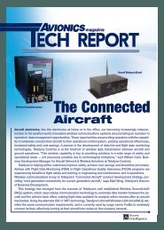
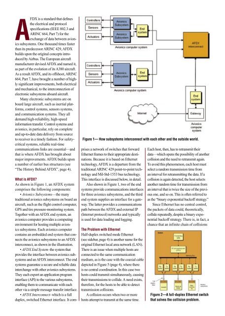
Figure 1— How subsystems interconnect with each other and the outside world.<br />
What is <strong>AFDX</strong>?<br />
As shown in Figure 1, an <strong>AFDX</strong> system<br />
comprises the following components:<br />
• Avionics Subsystems—the many<br />
traditional avionics subsystems on board an<br />
aircraft, such as the flight control computer,<br />
GPS and tire pressure-monitoring system.<br />
Together with an <strong>AFDX</strong> end system, an<br />
avionics computer provides a computing<br />
environment <strong>for</strong> hosting multiple avionics<br />
subsystems. Each avionics computer<br />
contains an embedded end system that connects<br />
the avionics subsystems to an <strong>AFDX</strong><br />
interconnect, as shown in the illustration.<br />
• <strong>AFDX</strong> End System–the system that<br />
provides the interface between avionics subsystems<br />
and an <strong>AFDX</strong> interconnect. <strong>The</strong> end<br />
systems guarantee a secure and reliable data<br />
interchange with other avionics subsystems.<br />
<strong>The</strong>y each export an application program<br />
interface (API) to the various subsystems,<br />
enabling them to communicate with each<br />
other via a simple message transfer interface.<br />
• <strong>AFDX</strong> <strong>Interconnect</strong>–which is a full<br />
duplex, switched Ethernet interface. It comprises<br />
a network of switches that <strong>for</strong>ward<br />
Ethernet frames to their appropriate destinations.<br />
Because it is based on Ethernet<br />
technology, <strong>AFDX</strong> is a departure from the<br />
traditional ARINC 429 point-to-point technology<br />
and Mil-Std-1553 bus technology.<br />
This interface is discussed below, in detail.<br />
Also shown in Figure 1, two of the end<br />
systems provide communications interfaces<br />
<strong>for</strong> three avionics subsystems, and the third<br />
end system supplies an interface <strong>for</strong> a gateway.<br />
<strong>The</strong> latter provides a communications<br />
path between the <strong>AFDX</strong> and external IP<br />
(Internet protocol) networks and typically<br />
is used <strong>for</strong> data loading and logging.<br />
<strong>The</strong> Problem with Ethernet<br />
Half-duplex switched mode Ethernet<br />
(see sidebar, page 4) is another name <strong>for</strong> the<br />
original Ethernet local area network (LAN).<br />
<strong>The</strong>re is an issue when multiple hosts are<br />
connected to the same communication<br />
medium, as is the case with the coaxial cable<br />
depicted in Figure 5 (page 4), where there<br />
is no central coordination. In this case two<br />
hosts could transmit simultaneously, causing<br />
their transmissions to collide. A need exists,<br />
there<strong>for</strong>e, <strong>for</strong> the hosts to be able to detect<br />
transmission collisions.<br />
A collision occurs when two or more<br />
hosts attempt to transmit at the same time.<br />
Each host, then, has to retransmit their<br />
data—which opens the possibility of another<br />
collision and the need to retransmit again.<br />
To avoid this phenomenon, each host must<br />
select a random transmission time from<br />
an interval <strong>for</strong> retransmitting the data. If a<br />
collision is again detected, the host selects<br />
another random time <strong>for</strong> transmission from<br />
an interval that is twice the size of the previous<br />
one, and so on. This is often referred to<br />
as the “binary exponential backoff strategy.”<br />
Since Ethernet has no central control,<br />
the packets of data could, theoretically,<br />
collide repeatedly, despite a binary exponential<br />
backoff strategy. <strong>The</strong>re is, in fact, a<br />
chance that an infinite chain of collisions<br />
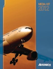
Figure 2—A full-duplex Ethernet switch<br />
that solves the collision problem.